
Every assembly technician has met this bracket. The holes are in exactly the right place, the inspection report is spotless, and the screwdriver still can’t get anywhere near the screw because a beautifully bent flange is standing in the way. The part passed inspection. It just can’t be assembled.
Quick answer: When sourcing custom sheet metal parts, OEM buyers should verify that every fastener can be installed, tightened, removed and serviced with the intended tools after fabrication and assembly. A mounting hole can meet its tolerance and still be useless if a bent flange blocks a screwdriver, a nearby wall stops a socket, or a welded bracket leaves no room to swing a wrench. Review fastener access and tool clearance before laser cutting, CNC bending, welding and hardware installation, and give your supplier a complete 3D assembly model, dimensioned drawings, fastener specifications and the intended installation sequence.
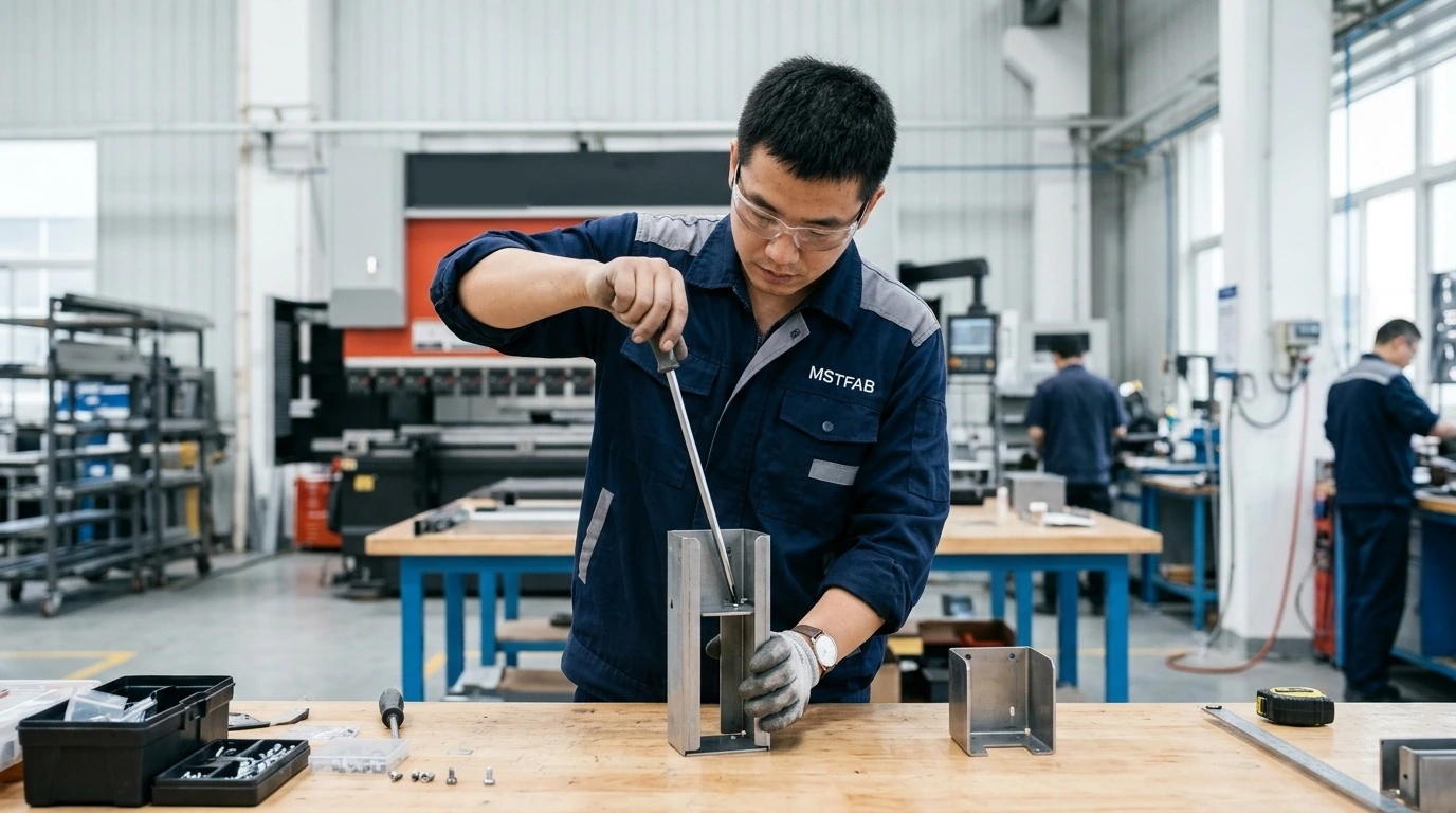
A qualified custom sheet metal fabrication supplier can review your drawings and flag manufacturing and assembly conflicts before metal is cut. This guide explains how OEM equipment manufacturers can prevent inaccessible fasteners, reduce assembly rework and improve the manufacturability of custom metal enclosures and brackets.
Why Fastener Access Matters in Custom Sheet Metal Fabrication
Custom sheet metal parts are full of holes, threaded inserts, mounting studs and other fastening features. They hold enclosure panels, mechanical supports, equipment chassis and removable covers together. But designing a hole is not the same as designing an accessible fastening connection.
Take a simple industrial equipment bracket. Dimensions, material thickness and hole pattern are all correct. After CNC bending, one flange partly covers the screw head. The technician can drop the screw in but can’t line the screwdriver up to tighten it. The part passes dimensional inspection and still fails its actual job. That is why tool access belongs in your design-for-manufacturability review, not in the assembly operator’s list of daily frustrations.
Common fastener access problems
| Assembly Problem | Possible Cause | Manufacturing Impact |
|---|---|---|
| Screwdriver cannot reach the screw | Nearby flange blocks the tool axis | Assembly interference |
| Socket cannot fit around bolt head | Insufficient radial clearance | Cannot tighten with the intended tool |
| Wrench cannot rotate | Nearby panel restricts movement | Extra installation difficulty |
| Nut cannot be installed | No access to the opposite side | Assembly sequence must change |
| Rivet nut tool cannot enter | Hole too close to a formed wall | Hardware installation may be impossible |
| Fastener inaccessible after welding | Joint enclosed by permanent structure | Rework or redesign may be needed |
| Coating interferes with threads | Masking not specified | Thread cleaning or corrective work |
Catching these on a drawing costs an email. Catching them on finished, powder-coated parts costs considerably more than that.
1. What Is Tool Clearance in Sheet Metal Design?
Tool clearance is the space an installation, manufacturing or maintenance tool needs to reach and operate on a feature. For fasteners, that means the screwdriver, socket wrench, torque tool, hex key, nut-setting tool or other approved equipment. It is not just the visible gap around the fastener head. It also covers the approach direction, the tool body, hand position where relevant, and any movement the tool needs to work.
Three types of tool clearance
There is no single universal clearance for every fastener and tool. The required space should come from the selected hardware, the real tool geometry and the approved assembly method. “Should be enough room” is not a dimension.
2. How CNC Bending Can Block Fastener Access
CNC bending turns a flat blank into a three-dimensional part. In the flat pattern, a mounting hole looks wide open. After bending, the same hole may sit at the bottom of a narrow channel or right beside a return flange.
Example: a U-shaped mounting bracket
A U-shaped steel bracket has mounting holes near its inner corners. Flat, they’re easy to reach. Once both side flanges are formed, their height and spacing can restrict the screwdriver’s approach. Add an internal reinforcement and the space gets tighter still.
The fix is not automatically “make the hole bigger”. Engineering alternatives include:
- Moving the mounting hole
- Changing the bend or flange geometry
- Using a different approved fastener head
- Fastening from another direction
- Changing the mechanical assembly sequence
- Reviewing another suitable joining method
Each change must be checked against the part’s structural and functional requirements, and the buyer’s engineering team should approve the final design. Our bend radius and flange design checklist covers the forming side, and you can learn more about our CNC sheet metal bending services.
3. Why Fastener Type Affects Assembly Space
Different fastening systems install in different ways. The right choice depends on enclosure geometry, material thickness, loading, service needs and the manufacturing process.
| Fastening Method | Main Access Requirement | Important Consideration |
|---|---|---|
| Conventional bolt and nut | Access to both sides unless one side is retained | Tool clearance on both sides |
| Self-clinching nut | Installation press access during production | Sheet thickness, hole preparation, insertion force |
| Rivet nut | Access for the setting tool | Tool nose and setting-stroke clearance |
| Weld nut | Weld access during fabrication | Joint design and thread protection |
| Threaded stud | Installation or welding access | Stud position and later assembly space |
| Captive screw | Installation and service access | Retention geometry and removal path |
| Tapped metal feature | Suitable material and thread engagement | Thread strength and tool access |
A fastener that works perfectly on a flat panel can become a problem once the part is bent or welded. A self-clinching nut, for example, generally needs press access and compatible sheet material and thickness. If surrounding flanges stop the press reaching the hole, the planned sequence simply doesn’t work. For more detail, see our guides to PEM hardware installation and threaded inserts in sheet metal.
OEM purchasing tip: Confirm the exact hardware manufacturer and part number before releasing the sheet metal drawings. Fasteners with the same nominal thread size do not necessarily have identical installation requirements. “M5 nut” is a thread size, not a specification.

4. When Should Hardware Be Installed During Fabrication?
Manufacturing sequence can decide whether a fastening system is practical. Some parts are best fitted with hardware while they’re still relatively flat; others can take hardware after forming or welding if the geometry and equipment allow.
| Process | Important Access Check |
|---|---|
| Laser cutting | Hole dimensions and required hardware preparation |
| Deburring | Edge condition suitable for later operations |
| Hardware installation | Tool access, installation force and orientation |
| CNC bending | Installed hardware must not obstruct press brake tooling |
| Welding | Avoid damage to threads and installed hardware |
| Surface finishing | Protect threads and functional contact areas as specified |
| Mechanical assembly | Confirm final fastener engagement and tool clearance |
| Inspection | Verify agreed hardware and assembled interfaces |
Illustrative sequence only. The correct production route varies by part.
Here’s the catch: installing fasteners before bending can avoid later access problems, but the hardware may then clash with the press brake tooling. Installing after bending avoids the tooling clash but may leave the hole unreachable. It’s a genuine trade-off, and the supplier should evaluate both routes before production, not discover the answer halfway through the batch.
5. Why Enclosure Assembly Requires More Than Hole Alignment
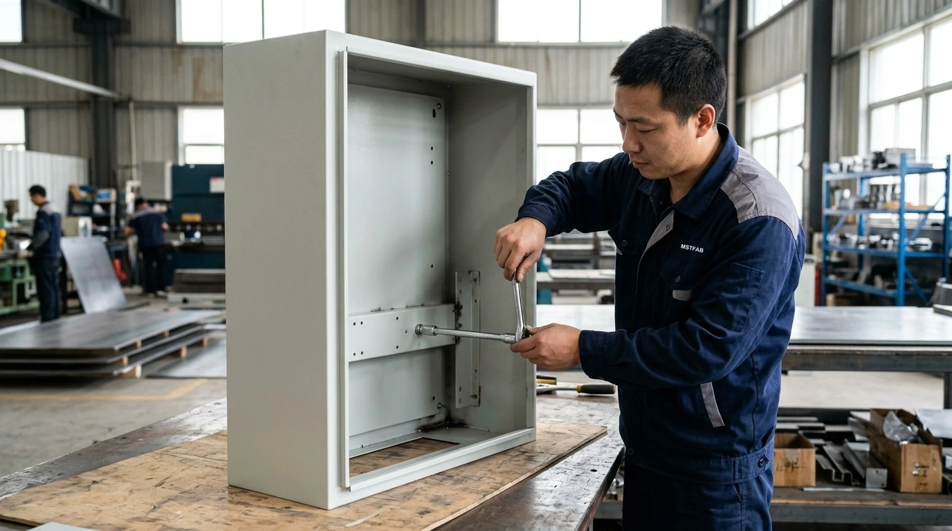
Industrial electronics enclosures and mechanical cabinets usually combine several metal parts: the enclosure body, removable covers, equipment mounting plates, internal brackets and access doors. A fastener can be perfectly positioned and still be inaccessible once another part is in the way.
Example: an industrial control enclosure
A custom control enclosure has an internal mounting plate fixed to two side brackets with four screws. At the first assembly stage, all four are easy to reach. Once an adjacent support panel goes in, two of them become very hard to get at. If the mounting plate ever needs to come out for service, the technician may have to dismantle several unrelated parts first. That turns a ten-minute job into an afternoon. A practical design considers initial assembly and future service access; our enclosure design guidelines and service-access mounting plate DFM example go further into this.
Questions buyers should ask
- Can every required fastener be installed with the specified tool?
- Is the installation direction clearly defined?
- Can the fastener be tightened without the tool hitting surrounding panels?
- Does another component block access at the final assembly stage?
- Can the part be removed for maintenance?
- Does the surface finish affect tool engagement or thread function?
- Is the fastening arrangement suitable for the intended mechanical loads?
These should be settled in engineering review, not left for the factory assembly operator to improvise.
6. How to Check Tool Clearance in a STEP Assembly Model
A STEP assembly model shows the supplier how the sheet metal parts connect. But having a complete model doesn’t prove that a tool can reach every fastening point. Parts in CAD don’t have hands. For important interfaces, add simplified tool-clearance envelopes.
What is a tool envelope?
A tool envelope is a simplified 3D shape representing the space the chosen installation tool needs, for example the outside diameter and approach length of a socket plus extension. With that shape in the model, the designer can check for interference with enclosure walls, brackets, flanges and nearby parts. The envelope should be based on the actual approved assembly method, not the slimmest tool anyone has ever seen.
Recommended CAD review
- Identify the fastener.Confirm part number, head type, thread specification and installation direction.
- Identify the tool.Decide which screwdriver, wrench, socket or other approved equipment will be used.
- Model the required access space.Include the approach direction and the operating space the tool needs.
- Check the assembled configuration.Review the tool envelope with neighbouring sheet metal parts in place.
- Verify the installation sequence.Confirm the fastening operation is possible at the intended stage of assembly.
- Record the approved requirement.Add access notes or critical dimensions to the controlled engineering documents.
A CAD review catches most conflicts before fabrication, but important interfaces may still need physical confirmation during prototype assembly. Our design for manufacturability guide and tolerances and assembly problems article cover the wider review.
7. What Happens When Welding Blocks Fastener Access?
Welding creates permanent connections. Once an enclosure frame or support structure is welded, some internal surfaces become very hard to reach. Picture a welded steel equipment base with a mounting bracket close to a surrounding wall. If the hardware location ends up enclosed by the welded structure, nobody can install that fastener afterwards. This is why welding and fastening have to be planned together.
Possible manufacturing alternatives
- Install selected hardware, such as weld nuts or studs, before welding
- Build a pre-assembled mechanical sub-component, then join it to the main structure
- Relocate the fastening interface or modify the structural arrangement
The right answer depends on heat exposure, hardware properties, welding access, assembly requirements and serviceability. Our articles on welding fixture control and welded vs. bolt-together enclosures are useful background.

Important: Never move a fastener without evaluating the joint’s mechanical performance. A convenient screw location is not necessarily a structurally suitable one.
8. How Does Powder Coating Affect Fastener Installation?
Powder coating changes the final dimensions of threaded and close-fitting features. A powder-coated steel panel may carry threaded inserts, studs or holes that need accurate fastener engagement. If powder gets into a thread or builds up on a mating surface, assembly gets difficult fast. Paint is very good at filling small gaps; unfortunately, threads are small gaps.
Common finishing considerations
- Thread protection: threads may need masking or other approved process controls.
- Grounding interfaces: where specified, conductive contact surfaces should be protected from insulating coating.
- Close-fitting hardware: coating build-up can affect tight-clearance interfaces.
- Cosmetic surfaces: assembly tools should not damage visible powder-coated or brushed surfaces.
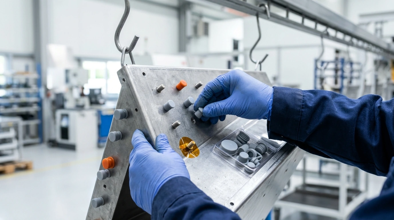
Coordinate the surface finishing process with the hardware and assembly requirements. For OEM projects, specify which areas must stay uncoated and which features must be checked after finishing.
9. How Can Buyers Reduce Assembly Rework Costs?
Fastener access problems create costs that never appear on the original quotation. The factory may deliver a bracket that meets every dimension, and the buyer only finds out later that extra installation work is needed. That can mean redesign, more fabrication, revised hardware or a changed assembly process.
| Problem | Possible Additional Cost |
|---|---|
| Inaccessible screw | Redesign or alternative installation method |
| Incorrect fastening direction | Rework of brackets or mounting panels |
| Hardware cannot be installed after bending | Production sequence change |
| Tool collides with finished panel | Extra clearance review or part modification |
| Coated threads obstruct assembly | Corrective finishing and re-inspection |
| Fastener cannot be serviced | Product redesign or extra maintenance labour |
| Incorrect assembly sequence | Longer assembly time and retraining |
These costs are project-specific, and there is no reliable universal percentage saving from adding tool-clearance reviews. Anyone quoting one is guessing. What a review does is reduce the chance of avoidable downstream changes. The purchasing goal is parts that meet both the drawings and the approved assembly requirements.
10. What Should OEM Buyers Include in a Tool-Access RFQ?
A complete RFQ communicates the part geometry and how the parts will be installed. See also our guide to what to send for a sheet metal quote.
Example RFQ: custom steel mounting bracket assembly
Project: Industrial equipment mounting bracket
Material: SPCC cold-rolled steel
Thickness: 2.0 mm
Manufacturing: Laser cutting, CNC bending and specified hardware installation
Surface finish: Black powder coating, RAL 9005
Order quantities: 10, 50, 100 and 500 pieces
Fastening requirements:
- Approved mounting-hole positions
- Specified threaded inserts or nuts
- Defined fastener installation direction
- Required screwdriver or socket access
- Approved mechanical assembly sequence
- Thread protection during finishing
- Final hardware engagement verification
Required documents: STEP/STP part and assembly models; dimensioned PDF drawings; hardware part numbers; BOM where applicable; installation notes; critical inspection requirements.
Quotation request: Please review the sheet metal geometry, bending sequence, hardware installation access and final assembly clearances. Advise if any features may interfere with the specified manufacturing or fastening processes. Provide unit pricing for the requested quantities, including the agreed fabrication, hardware installation, finishing and inspection scope.
An RFQ like this lets the supplier spot problems before manufacturing starts, which is the cheapest moment to spot anything.
11. What Inspection Evidence Should Buyers Request?
Dimensional inspection still matters, but it doesn’t prove a fastener can actually be installed. For selected critical interfaces, a practical installation check adds the missing evidence.
| Verification Item | Purpose |
|---|---|
| Hole position and diameter | Confirm drawing compliance |
| Hardware identity | Verify approved fastener components |
| Hardware orientation | Prevent reverse installation |
| Bend geometry | Confirm required clearance |
| Tool-access check | Verify the installation tool can reach the fastener |
| Thread engagement | Confirm required fastener function |
| Finished-state verification | Check coating and post-processing effects |
| Mechanical trial assembly | Confirm installation in the intended configuration |

Some projects use a representative tool or checking fixture at first-piece inspection; others are better served by a trial assembly with actual hardware and mating parts. Agree the inspection scope before production. For new parts, building this into a pilot run works well.
Keep in mind: An installation check confirms accessibility under the tested conditions. It does not by itself establish joint strength, vibration resistance or product-level safety.
Fastener Access Supplier Trust Table
A few questions that show whether a supplier thinks about assembly or just about geometry.
| Question to Ask | A Reliable Answer Sounds Like | Red Flag |
|---|---|---|
| How much clearance does this fastener need? | “Depends on the hardware, the tool and the approach direction. Which tool will you use?” | One standard number for every fastener. |
| Will you install hardware before or after bending? | Explains the trade-off between tooling interference and later access for your part. | “We always do it the same way.” |
| Can the press reach this self-clinching nut? | Checks the formed geometry and the specific hardware part number before quoting. | “Sure, any M5 nut is fine.” |
| What happens to threads during powder coating? | Describes masking and post-finish thread checks as specified. | “We’ll run a tap through them afterwards” as the default plan. |
| What if a fastener turns out to be blocked? | Stops, reports and proposes options for your engineers to approve. | Quietly moves the hole or grinds the flange. |
| How will you prove the fastener can be installed? | Offers a tool-access check or trial assembly on the first pieces. | “The dimensions are in tolerance.” |
12. How MSTFAB Supports Fastener-Ready Sheet Metal Fabrication
Guangzhou Maisituo Sheet Metal Manufacturing Co., Ltd. (MSTFAB) provides custom sheet metal fabrication for international OEM equipment manufacturers. Our capabilities include laser cutting, CNC sheet metal bending, TIG/MIG welding, grinding and deburring, custom metal enclosure fabrication, equipment panels and mounting brackets, drawing-defined hardware features, mechanical assembly within the agreed scope, dimensional inspection and export packaging. We work with carbon steel, 304/316 stainless steel, 5052/6061 aluminum and galvanized steel.
For projects with threaded inserts, mounting brackets or enclosure hardware, send us complete assembly drawings for a manufacturability review. Our engineers look at cutting and bending requirements, manufacturing sequence, fastening interfaces and potential assembly conflicts. Where specified, hardware sourcing or installation can be included in the agreed scope. Surface finishing is coordinated through established finishing partners. More on our custom sheet metal fabrication services.
Scope, plainly: MSTFAB specializes in custom metal enclosure shells and mechanical components. Electronic components, wiring, software and finished electronic system integration are outside our standard fabrication scope.
Key Takeaways
- A hole in tolerance is not the same as a fastener you can install. Check both.
- Review axial, radial and operating clearance using the real tool, not a guess.
- Bending, welding and coating can all block or spoil access that existed in the flat pattern.
- Confirm exact hardware part numbers; the same thread size can install very differently.
- Decide the hardware installation sequence before production, not during it.
- Put tool envelopes in the STEP model for critical fasteners and record approved requirements.
- Ask for a tool-access check or trial assembly on first pieces; it proves access, not strength.
Frequently Asked Questions
Why can a dimensionally correct sheet metal bracket still fail assembly?
The holes and overall dimensions may meet the drawing while surrounding geometry blocks the installation tool. Tool access and assembly sequence need to be evaluated separately from basic dimensional conformity.
How much clearance is required around a sheet metal fastener?
There is no universal value. It depends on the selected fastener, installation tool, approach direction, nearby geometry and the operating space the tool needs.
Can self-clinching nuts be installed after sheet metal bending?
Sometimes. It depends on the installation equipment, material thickness, hole location and how accessible the formed part is.
Does laser cutting guarantee proper fastener fit?
No. Laser cutting produces drawing-defined holes, but hardware fit also depends on hole preparation, material condition, fastener selection, installation method and final assembly geometry.
Can powder coating interfere with screws and threaded inserts?
Yes. Coating build-up can affect threads and other close-fitting interfaces. Specify masking and post-finish inspection where needed.
Should fasteners be installed before or after bending?
It depends on part geometry, available tooling, fastener type and interference risk. The fabrication supplier should review the proposed production route.
Can MSTFAB manufacture sheet metal components with fastening features?
Yes. MSTFAB evaluates drawing-defined mounting holes, studs, brackets, threaded hardware interfaces and related mechanical fabrication requirements according to the approved project scope.
What documents should buyers send for a fastening-access review?
STEP/STP models, dimensioned PDF drawings, selected hardware part numbers, material specifications, quantities and the intended assembly arrangement.
Design for Installation, Not Just Manufacturing
Custom sheet metal fabrication is about more than accurate metal shapes. For equipment manufacturers, parts also have to be practical to assemble and service. Mounting holes, threaded inserts, formed flanges, welded supports and surface finishes all affect whether a fastener can be installed correctly.
The most effective approach is to evaluate tool access and manufacturing sequence before production. A complete CAD assembly, defined hardware and a practical installation check catch problems before a full order is released. A good custom sheet metal part should not only fit its mating components; it should let the intended fastening and assembly operations be completed without unapproved modifications.
Request a Custom Sheet Metal Fabrication Quote
Need custom steel or aluminum brackets, equipment panels, enclosure shells or mechanical assemblies with specific mounting and fastening requirements? Send your STEP/STP files, dimensioned PDF drawings, material requirements, hardware specifications and planned order quantities. Our team will review the manufacturing scope and provide a project-specific quotation.
Request a Custom Fabrication Quote
Explore Custom Sheet Metal Fabrication
View CNC Bending Services
 WeChat Contact
 WhatsApp Me Directly