
A sheet metal enclosure is not just a box. It must protect, mount, open, close, wire, ventilate, ground, assemble, finish, ship, and repeat in production. A clean 3D CAD model may look flawless on a screen, but real-world sheet metal fabrication includes laser cutting, CNC bending, welding, hardware insertion, powder coating, and assembly inspection. Understanding Design for Manufacturability (DFM) prevents door alignment disasters, paint failures, and costly production delays.
The Reality vs. CAD Enclosure Design Breakdown
Before diving into the engineering details, let’s address the gap between CAD theory and actual factory floor reality. Many enclosure failures trace back to a few critical sourcing pain points. Understanding these makes the transition from drawing to physical metal smooth and predictable.
| Sourcing Pain Point | What CAD Thinks | What Reality Does | MSTFAB DFM Solution |
|---|---|---|---|
| Bending & Tolerances | Perfect 90° sharp corners, 0.0mm tolerance | Springback, material stretching, door won’t shut | Standard bend radius, 1.5mm door gap clearances |
| Hardware Insertion | Standoffs placed 1mm from the edge or bend | PEM studs pop out, sheet metal deforms | Keep hardware edge distance at least 1.5x hole diameter |
| Welding & Warpage | Continuous seamless welding everywhere | Thin sheet metal warps like a potato under heat | Stitch welding, tab-and-slot alignment, structural rivets |
| Powder Coating | Fully coated and perfect grounding | Powder coat blocks grounding; overspray locks threads | Dedicated grounding studs, silicone caps, masking zones |
| Ventilation & Airflow | Hundreds of micro-slots closely spaced | Laser nozzle melts the metal webs; high cost | Optimized spacing (> material thickness) or standard louvers |
To understand the cost dynamics of these design decisions, explore our guide on sheet metal fabrication cost for enclosures. For a broader look at designing sheet metal structures, check out DFM for sheet metal enclosures. When you’re ready to proceed with production, you can explore our complete capabilities in custom sheet metal enclosure fabrication.
7 Essential DFM Guidelines for Sheet Metal Enclosures
1. Laser Cutting & Hole Spacing Rules
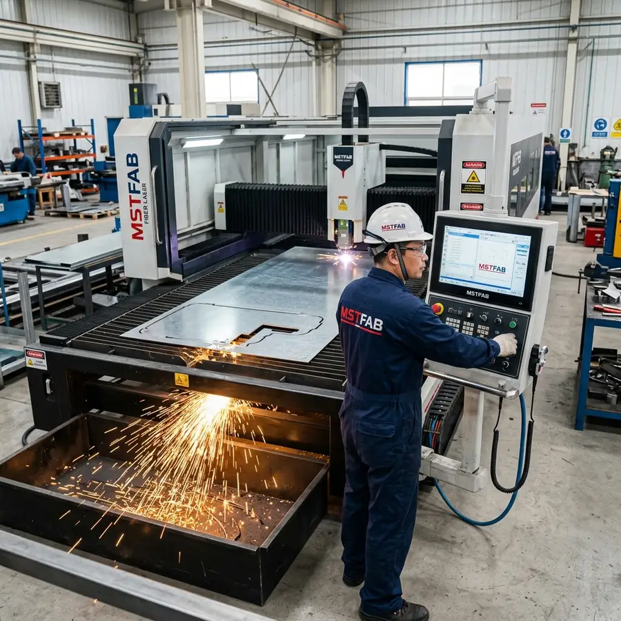
Every hole, slot, or cutout must respect the physics of the laser. Holes with diameters smaller than the material thickness are difficult to cut cleanly because the heat concentrates. Additionally, keep holes at least 2x the material thickness away from any bend line. If they are too close, the bending tool will stretch the metal, turning your perfectly circular bolt holes into useless ovals.
2. Bending Limits & Springback Clearances
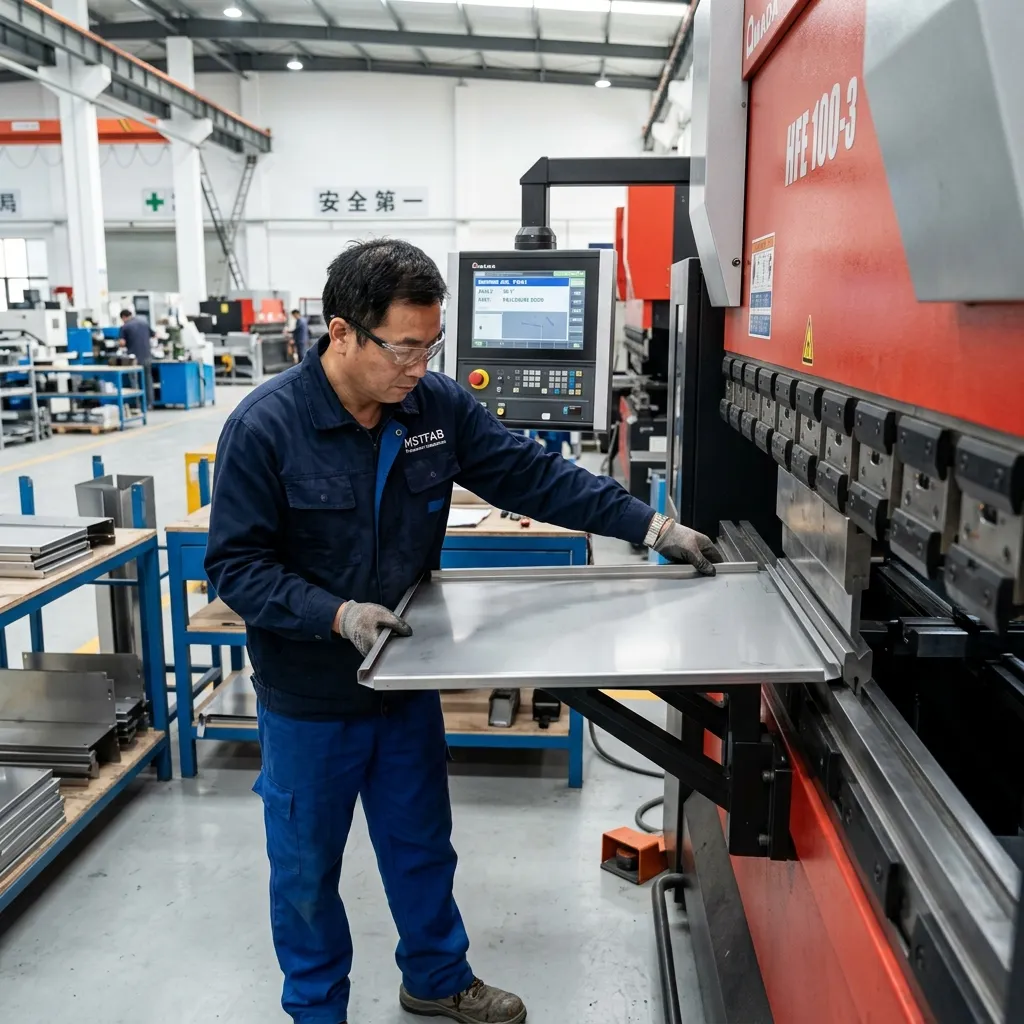
Bending is not just folding paper. Metal has elastic memory, known as springback, and it stretches along the bend line. To prevent cracks, design the internal bend radius to be at least equal to the material thickness. Ensure that flange lengths are long enough to rest securely on the press brake die during forming; otherwise, the tool cannot grip the part, leading to inaccurate bend angles and deformed shapes.
3. Weld Joint Access & Heat Distortion Control
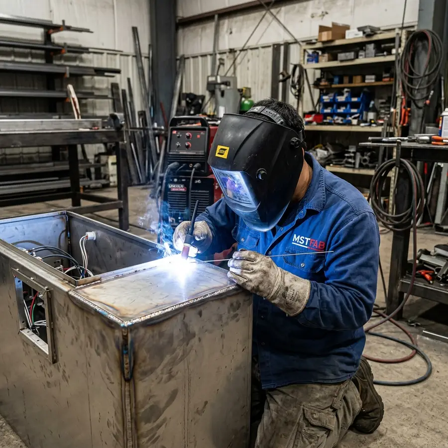
A full seam weld makes an enclosure strong, but excessive welding heat will warp thin sheet metal. Incorporate stitch welding or spot welding where possible. If you must have continuous welds for NEMA/IP liquid-tight seals, ensure the design provides adequate gun clearance (at least 30mm) so the welder can access the corner joint at the correct angle for deep penetration.
4. Hardware Insertion & PEM Edge Distances
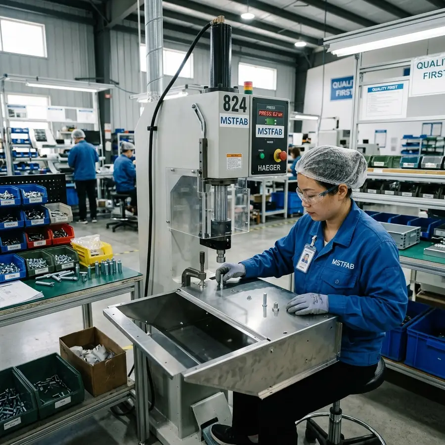
Self-clinching fasteners (like PEM nuts and standoffs) are excellent for mounting internal components. However, pressing hardware deforms the metal around the hole. Always keep fasteners at least 1.5x the hole diameter away from the sheet edges or bend lines. Placing them too close to a bend will cause the fastener to tilt or fail when torqued during final assembly.
5. Door Fit, Hinges & Lock Clearances
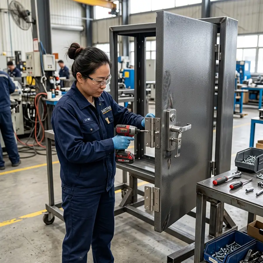
A common mistake in enclosure design is neglecting paint buildup when calculating door tolerances. Powder coating adds 0.1mm to 0.15mm of thickness on every surface. If your door has a 0.5mm nominal clearance gap, the paint buildup will cause the door to scrape, jam, or scrape the finish off. Design with a minimum door-to-frame gap clearance of 1.5mm. Use adjustable hinges to allow alignment corrections during assembly.
6. Powder Coating & Grounding Area Masking

Powder coating provides excellent environmental protection, but it is an electrical insulator. Grounding studs, door grounding points, and gland plate contacts must remain free of paint. Specify masking zones clearly on your engineering drawings. MSTFAB uses custom-fit high-temperature silicone caps and masking tape to protect threads and contact patches, ensuring solid metal-to-metal electrical ground paths.
7. Quality Inspection & Assembly Checking
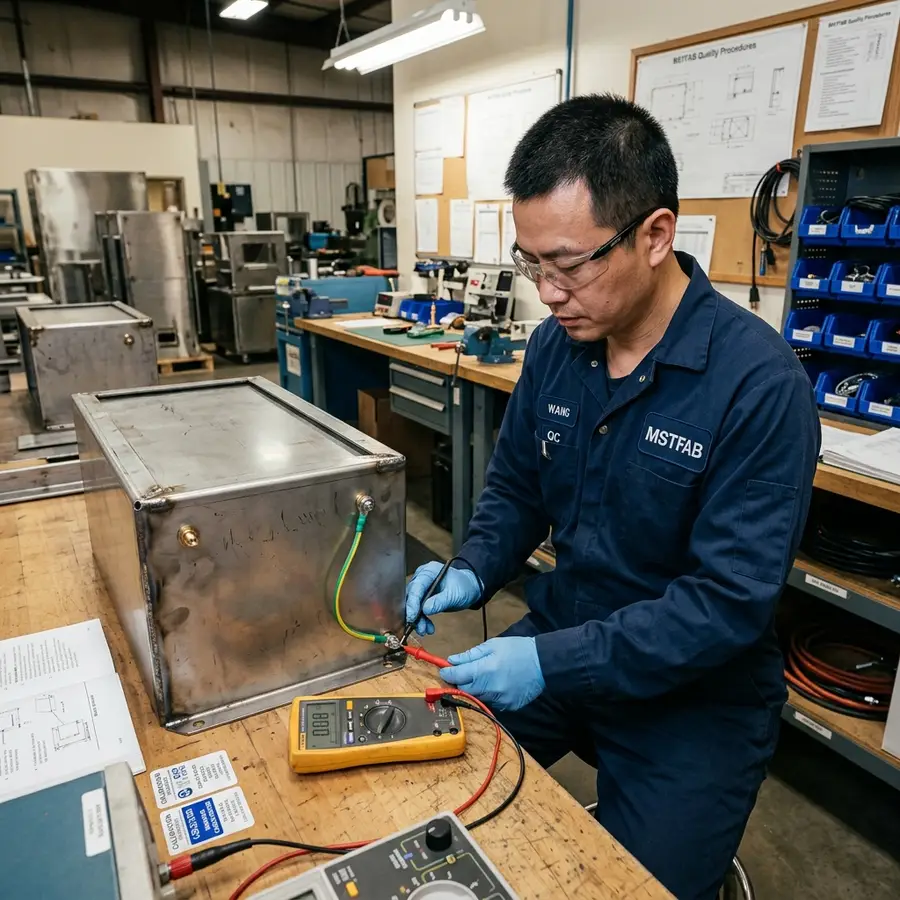
The final step in a reliable enclosure fabrication process is grounding safety verification. Every door and removable panel must connect to the main chassis via a flexible copper grounding strap. Our quality control team inspects door sealing gaskets, lock alignments, paint thickness, and electrical continuity to guarantee that your enclosures perform safely and durably in the field.
Ready to Get an Accurate Custom Enclosure Quote?
Fill out our simple inquiry form, upload your 3D CAD models (STEP format) along with 2D drawings pointing out your critical tolerances, masking areas, and hardware specs. MSTFAB engineering team will perform a full DFM analysis and provide a detailed quotation for your production run.
MSTFAB manufactures custom sheet metal enclosures, electrical cabinets, control boxes and industrial metal housings for OEM buyers.
 WeChat Contact
 WhatsApp Me Directly