
Release a telecom cabinet airflow path only after the controlled package defines the intake, exhaust, pressure zones, equipment blockage, fan and filter interfaces, cable routes, service states and responsible system validation.
Open holes are not an airflow plan. Air, unlike a neat CAD arrow, does not politely ignore a cable bundle, a clogged filter or the back of a switch. The drawing needs a continuous route and clear ownership from inlet to outlet.
Use the guide that owns the decision you are making.
Three related questions appear in the same RFQ, but they need different inputs and evidence. Separating them keeps the drawing useful and prevents a sheet metal feature from becoming an accidental performance promise.
Choose the cooling method
Use the heat-load and cooling-method guide for ambient conditions, heat load, passive versus active cooling and equipment sizing ownership.
Mount active cooling hardware
Use the active cooling component mounting and sealing interface checklist for a selected air conditioner or heat exchanger.
Release the airflow path
This page controls ventilation geometry: openings, perforations, louvers, baffles, fan and filter interfaces, pressure zones, cable conflicts and service access.
Give every thermal input and physical feature an owner.
The fabricator can inspect a cutout, panel, bracket or duct. The completed cabinet still needs the responsible engineering team to prove airflow, temperature, environmental performance and compliance in the installed configuration.
OEM or thermal designer
Controls equipment heat load, ambient limits, target airflow, pressure strategy, component selection, controls and completed-system validation.
Equipment owner
Provides controlled models, fan curves or interface data, airflow direction, keep-out zones, connector locations, mass and service envelope.
Shell fabricator
Reviews manufacturability and produces the released openings, perforations, louvers, baffles, brackets, ducts, covers, finish and agreed evidence.
Integrator or test party
Installs equipment and filters, manages wiring and seals, and verifies the completed assembly under the agreed operating and environmental conditions.

Control the route from intake to exhaust.
The release package should make recirculation, bypass and blocked service routes visible before metal is cut. A dimension without its operating state can still be wrong, so pair geometry with the condition in which it must work.
| Interface | Buyer-controlled input | Fabrication or FAI check |
|---|---|---|
| Intake and exhaust | Location, size, airflow direction, pressure relationship, separation distance and keep-out zones around walls or nearby cabinets. | Finished opening size, position, edge condition, panel orientation and physical separation. |
| Perforation or louver | Pattern, pitch, bridge width, opening direction, required geometric open area and any weather or safety constraint. | Pattern dimensions, flatness, burr direction, orientation and finish coverage. |
| Fan and filter | Selected component, mount, airflow direction, connector, removal route, filter media and replacement interval assumptions. | Cutout, hole pattern, bracket fit, fastener access and unobstructed filter removal. |
| Baffle or duct | Pressure-zone boundary, target route, joints, clearances, leakage-critical seams and removable sections. | Position, gaps, joint construction, fasteners and fit in the released assembly state. |
| Equipment and cable blockage | Installed equipment envelopes, cable bend zones, tie points, door loops and maximum allowed intrusion into the air path. | Physical clearance to brackets, rails, panels and cable-management features. |
| Water and drainage | Rain exposure, splash path, condensate source, drain route, trap or hose interface and validation responsibility. | Louver direction, shield and drain geometry, seam condition and outlet location. |
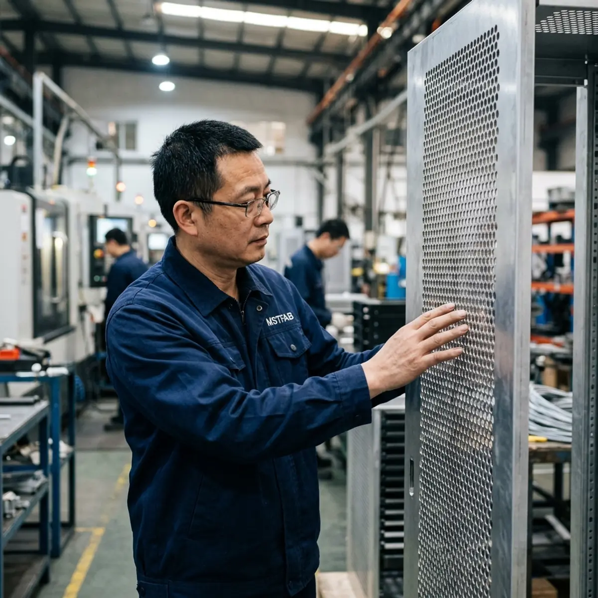
Check the cabinet when it is working and when someone must service it.
The same filter that fits during assembly may be impossible to remove beside a fence or with a loaded rack. Review these states with the same seriousness as the closed beauty shot.
Confirm seals, panel gaps, intake and exhaust separation, and the final installed obstruction map.
Show active fans or cooling equipment, pressure zones, recirculation barriers and cable positions.
Reserve the pull path, hand clearance, fastener access and a safe place for the removed cover.
Check cable loops, baffles, fan guards, hinges and nearby site obstacles through the full swing.
Protect louvers, screens, ducts and protruding mounts from packaging loads and handling damage.
Open area, stiffness, sealing and service access must coexist.
Removing metal changes more than airflow. A dense perforation field can reduce door stiffness. Louvers need forming access and a controlled direction. Filter retainers need room for insertion and replacement. Fan guards and cable routes need a no-contact zone. Review the set as one mechanical system.
Perforated panels
Specify the pattern boundary, edge margins, bridge width, cosmetic face, flatness-sensitive zones and how open area is calculated.
Louvers and shields
Define direction, forming clearance, rain or splash path, insect screen, solar-shield gap and mounting sequence.
Fan and filter hardware
Release the actual component interface, guard, bracket, seal, connector and tool or replacement envelope.
Baffles and ducts
Control pressure-zone boundaries, removable joints, service panels, edge treatment and conflicts with rack hardware.
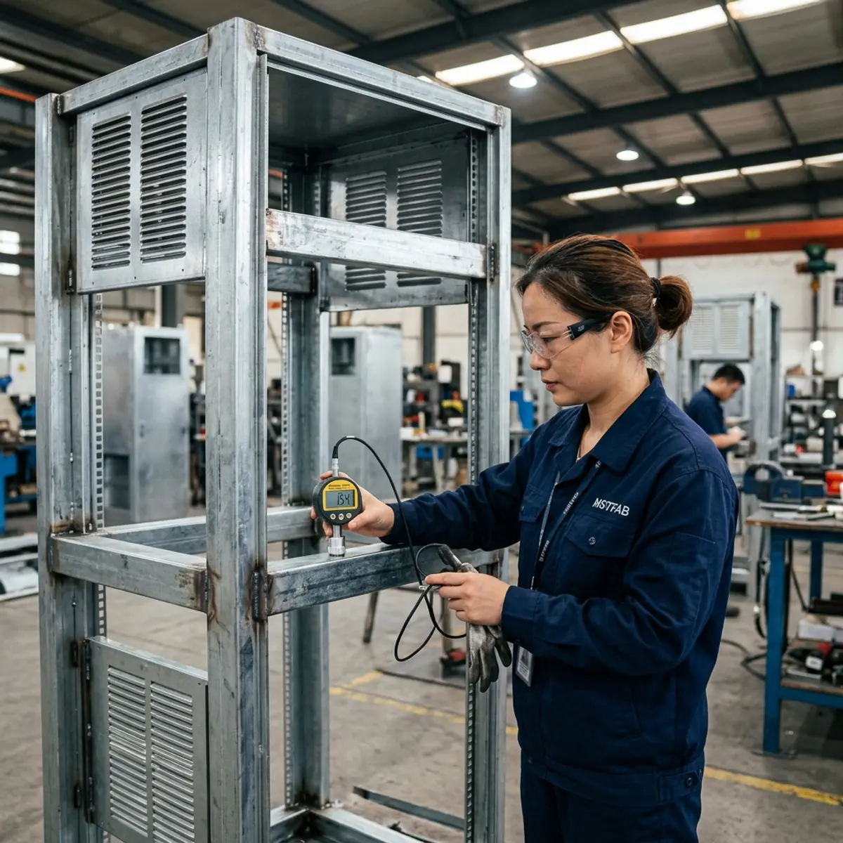

Ask for records tied to the released revision.
Evidence is useful when it answers a named risk. A folder of unlabeled photographs is still a folder of photographs, just with more scrolling.
Freeze inputs
Identify the drawing revision, equipment models, operating states, CTQs, finish and responsible validation plan before release.
Inspect physical interfaces
Measure openings, mounts, baffles, louver direction, filter path, cable clearances and agreed assembly conditions.
Release changes deliberately
Record deviations and route airflow-affecting changes back to the responsible OEM or thermal designer before production.
For recorded measurements and report structure, review MSTFAB’s dimensional inspection report guide.
Send enough information to quote the real cabinet.
Provide a STEP or STP assembly, a controlled 2D PDF, and DXF or DWG data when buyer controlled. Mark the revision and separate system requirements from fabrication CTQs.
- Equipment layout and heat-load owner
- Intake, exhaust and airflow direction
- Fan, filter and cooling-component data
- Pressure zones, baffles and ducts
- Cable paths and installed obstructions
- Service and replacement envelopes
- Material, finish and cosmetic faces
- Quantities and required FAI evidence
MSTFAB does not publish one MOQ, lead time or tolerance for every cabinet. Those terms depend on geometry, material, feature density, welding, hardware, finishing route, inspection, quantity and packing. Selected finishing processes may be completed by qualified long-term partners and are identified through the approved project scope.
Telecom cabinet airflow FAQ
What does MSTFAB supply for a telecom cabinet airflow project?
MSTFAB supplies drawing-based fabricated mechanical parts and empty enclosure shells, including perforated doors, louvered panels, fan openings, filter retainers, baffles, ducts, brackets, covers and related hardware interfaces. Fans, cooling units, controls, wiring, system integration and completed-system validation remain with the buyer or responsible OEM unless an approved quotation states otherwise.
Who selects the fan, air conditioner or heat exchanger?
The OEM or responsible thermal designer should define the equipment heat load, ambient conditions, pressure and airflow requirements, cooling method and selected component. MSTFAB can review and fabricate the released mechanical geometry for that decision.
Does a high perforation percentage guarantee enough airflow?
No. Open area is only one input. Fan curve, system resistance, filters, equipment blockage, recirculation, pressure zones and the installed operating state affect actual airflow. The system owner should validate performance in the completed configuration.
Do louvers, filters or gaskets prove an IP or NEMA rating?
No. Those are physical features, not a rating by themselves. The applicable standard, complete assembly, installation details and verification plan determine the result. The drawing should name both the controlled geometry and the party responsible for validation.
Which files should an airflow-ready cabinet RFQ include?
Send a STEP or STP assembly, a controlled 2D PDF, and DXF or DWG data when buyer controlled. Add equipment envelopes, heat and airflow ownership, fan and filter data, pressure zones, cable routes, service states, materials, finish, quantities, CTQs and required first-article evidence.
Does MSTFAB publish one MOQ, lead time or tolerance for every cabinet?
No. Cabinet size, material, perforation or louver pattern, forming, welding, hardware, finishing route, inspection scope, order quantity and packing all affect the quotation. Feasible tolerances, quantity and schedule are confirmed from the released package.
Release the airflow geometry before releasing the metal.
Send the cabinet assembly, equipment envelopes, airflow ownership, service states and critical interfaces. MSTFAB will review the drawing-defined sheet metal scope and return project-specific questions for quotation.
 WeChat Contact
 WhatsApp Me Directly