Release a cabinet cooling-hardware interface only after the selected component, cutout datums, mass and center of gravity, support path, fasteners, seal, drain, cable route, service envelope and validation owner are controlled.
"Cooling ready" is not a manufacturing dimension. A heavy unit attached to an unreviewed door quietly turns the hinge into the project manager, and hinges are poor project managers.
Separate component selection, airflow and physical mounting.
These decisions affect one cabinet, but they should not share one vague specification. Give each decision an owner and link it to the drawing or verification record that controls it.
Select the cooling method
Use the heat-load and cooling-method guide for ambient conditions, heat load, capacity and passive-versus-active decisions.
Release the airflow route
Use the airflow-path and ventilation release guide for openings, pressure zones, perforations, filters, baffles and cable blockage.
Release the hardware interface
This page owns the cutout, mount, reinforcement, seal, drain, connector and service envelope for the selected air conditioner, heat exchanger or thermoelectric cooling (TEC) unit.
Freeze the component before the cabinet interface.
A sales-page outline is not enough. The mechanical release needs controlled component data and named owners for structural input, sealing, wiring, drainage and completed-system tests.
OEM or thermal designer
Defines heat load, ambient limits, cooling method, required capacity, operating state and the completed-system validation plan.
Cooling-component owner
Provides a controlled model or drawing, mass, center of gravity, loads, cutout, fasteners, gasket, connector, drain and service instructions.
Shell fabricator
Reviews manufacturability and produces the released cutout, reinforcement, bracket, gasket land, cover, duct and drain geometry with agreed evidence.
Integrator or test party
Installs the selected unit, wiring and drains, manages field conditions, and verifies thermal, ingress, environmental and compliance performance.
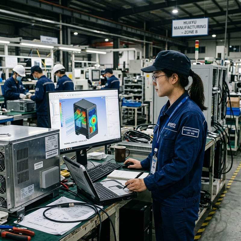
Put the load path, seal and service route on the release package.
Use the component manufacturer’s controlled data as an input, then identify the cabinet features and inspection evidence required for the actual installation. The six interfaces below catch most expensive surprises before coating.
| Interface | Buyer-controlled input | Fabrication or FAI check |
|---|---|---|
| Component identity | Manufacturer, model, revision, approved substitute rule and controlled drawing or sample status. | Recorded reference used for DFM, trial fit and released production drawing. |
| Cutout and datums | Finished opening, corner details, hole pattern, mounting side, datum scheme and allowable adjustment. | Opening size and position, edge condition, hole location and finished-panel alignment. |
| Mass and support path | Mass, center of gravity, static and service loads, vibration input when relevant, and required support points. | Reinforcement location, joint condition, panel flatness, hinge and latch operation, and approved load evidence. |
| Seal and closure | Gasket identity, mating flange, joint positions, compression approach, fasteners and penetrations. | Mating-land width and condition, hole and joint location, hardware access and closed-state fit. |
| Drain and cable route | Condensate source, drain connection, hose or trap route, connector location, bend radius, grounding and keep-out zones. | Outlet and bracket geometry, route clearance, edge protection and conflict check in the installed state. |
| Service and replacement | Door swing, filter or cover removal, tool access, lifting method, disconnect sequence and site clearance. | Unobstructed removal envelope, fastener reach, door support and trial-fit photographs when specified. |
Support the selected load without losing door function.
A door-mounted cooler or heat exchanger adds weight away from the hinge line. It can alter panel flatness, latch engagement, gasket compression and the effort needed during service. Start with the buyer’s real component mass and center of gravity, not a generic cabinet thickness rule.
Load path
Show how the component load reaches stiffeners, frame members, hinges, base or dedicated brackets.
Weld sequence
Review joint access and distortion risk around large openings before the mounting plane is finished.
Door hardware
Check hinge capacity input, latch alignment, hold-open devices and safe service movement with the unit installed.
Finished fit
Include coating allowance, captive hardware, gasket engagement and any controlled trial-fit component or gauge.
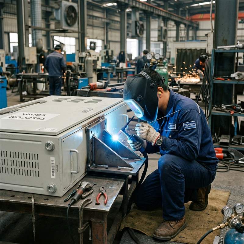
Inspect the mechanical boundary without inventing a rating.
A gasketed flange, rain shield or drain feature can be measured and photographed. None proves an IP or NEMA result by itself. Keep physical evidence and completed-assembly validation in separate columns.
Confirm cutout, holes, reinforcement, joint access and major distortion before finishing.
Check masking, coating build, gasket land, hardware and the controlled component or fit gauge.
Review closure, cable and drain routes, airflow openings, vibration inputs and nearby obstructions.
Verify fastener access, disconnect route, door support, tool clearance and safe replacement space.
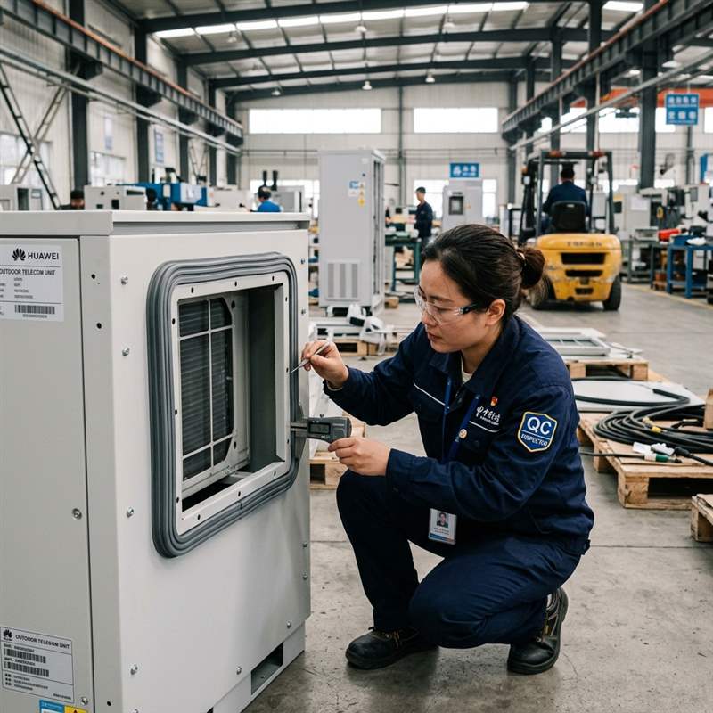
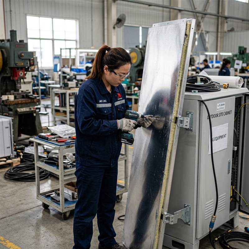
Ask for records that answer the interface risks.
Keep the evidence tied to the drawing revision and component identity. "Checked OK" is short, cheerful and almost useless when the component changes six months later.
Freeze the baseline
Record the component model, revision, cabinet drawing, assembly state, CTQs and responsible validation party.
Inspect the interface
Measure cutouts, mounts, reinforcement and seal features; check drain, cable, door and removal clearances.
Control deviations
Route any component or cabinet change that affects load, seal, fit, airflow, wiring or service back to the responsible owner.
For recorded measurements and report structure, review the dimensional inspection report guide.
Send the cooling component with the cabinet files.
Provide a STEP or STP assembly, a controlled 2D PDF, and DXF or DWG data when buyer controlled. Include the selected component drawing or sample status and mark system requirements separately from fabrication CTQs.
- Component model and revision
- Mass, center of gravity and loads
- Cutout, holes and cabinet datums
- Support and reinforcement inputs
- Gasket, flange and penetrations
- Drain, cable and grounding routes
- Service and replacement envelope
- Quantity and required FAI evidence
MSTFAB does not publish one MOQ, lead time or tolerance for every cabinet. Geometry, component load, material, welding, hardware, sealing details, finishing route, inspection, quantity and packing shape the quotation. Selected finishing processes may be completed by qualified long-term partners and are identified through the approved project scope.
Outdoor telecom cooling-interface FAQ
What does MSTFAB supply for an outdoor telecom cabinet cooling interface?
MSTFAB supplies drawing-based fabricated mechanical parts and empty enclosure shells, including cooling-unit cutouts, reinforced mounting panels, brackets, gasket lands, covers, ducts, drip trays, drain features and related hardware interfaces. Cooling equipment, refrigerant circuits, electrical design, controls, field installation and completed-system validation remain with the buyer or responsible OEM unless an approved quotation states otherwise.
Who selects and sizes the air conditioner or heat exchanger?
The OEM or responsible thermal designer should define the equipment heat load, ambient conditions, cooling method, required capacity and selected component. MSTFAB can review manufacturability and fabricate the approved mechanical interface for that selection.
What information is needed for a door-mounted cooling unit?
Provide the controlled component drawing or sample, mass, center of gravity, operating vibration input when relevant, cutout and hole pattern, support condition, gasket interface, connector and drain locations, door swing, removal envelope and required inspection evidence.
Does a gasketed cooling-unit cutout prove IP65 or a NEMA rating?
No. A gasket and mating land are inspectable mechanical features, but a rating depends on the applicable standard, complete assembly, installed component, penetrations, closure and verification plan. The responsible party should be named in the released package.
What first-article checks are useful for the cooling interface?
Useful checks may include cutout size and position, mounting-plane flatness, reinforcement location, fastener access, finished-condition trial fit, gasket-land condition, door and latch operation, drain geometry, cable clearance and photographs tied to the drawing revision.
Does MSTFAB publish one MOQ, lead time or tolerance for every cooling-ready cabinet?
No. Cabinet size, cooling-unit load, material, reinforcement, welding, hardware, sealing details, finishing route, inspection scope, quantity and packing affect the project. Feasible tolerances, quantity and schedule are confirmed from the released drawings and quotation.
Release the selected component and cabinet interface together.
Send the cooling-hardware data, cabinet assembly, loads, seal and drain details, service states and CTQs. MSTFAB will review the drawing-defined sheet metal scope and return project-specific questions for quotation.
 WeChat Contact
 WhatsApp Me Directly