
Release a network cabinet only after the controlled package fixes the rack datums, rail pattern, usable equipment envelope, door and service states, cable routes, airflow interfaces, installed loads and first-article evidence.
"19-inch cabinet" is a product description, not a complete fabrication baseline. A shell can look square in a photograph and still make the first switch installation feel like furniture assembly with the wrong bag of screws.
Give the rack interface, equipment and verification an owner.
A useful release package separates cabinet geometry from installed-system performance. That lets the fabricator inspect the physical interfaces without making claims about equipment it does not supply.
OEM or integrator
Controls equipment architecture, rack standard, heat load, cable strategy, electrical design, software and completed-system validation.
Equipment owner
Provides controlled models, masses, connector locations, airflow direction, service envelopes and mounting requirements.
Shell fabricator
Reviews manufacturability and produces the released frame, panels, brackets, hardware interfaces, finish and agreed inspection evidence.
Installer or test party
Owns site anchoring, field wiring, equipment installation and any completed-cabinet load, thermal, bonding or compliance test.
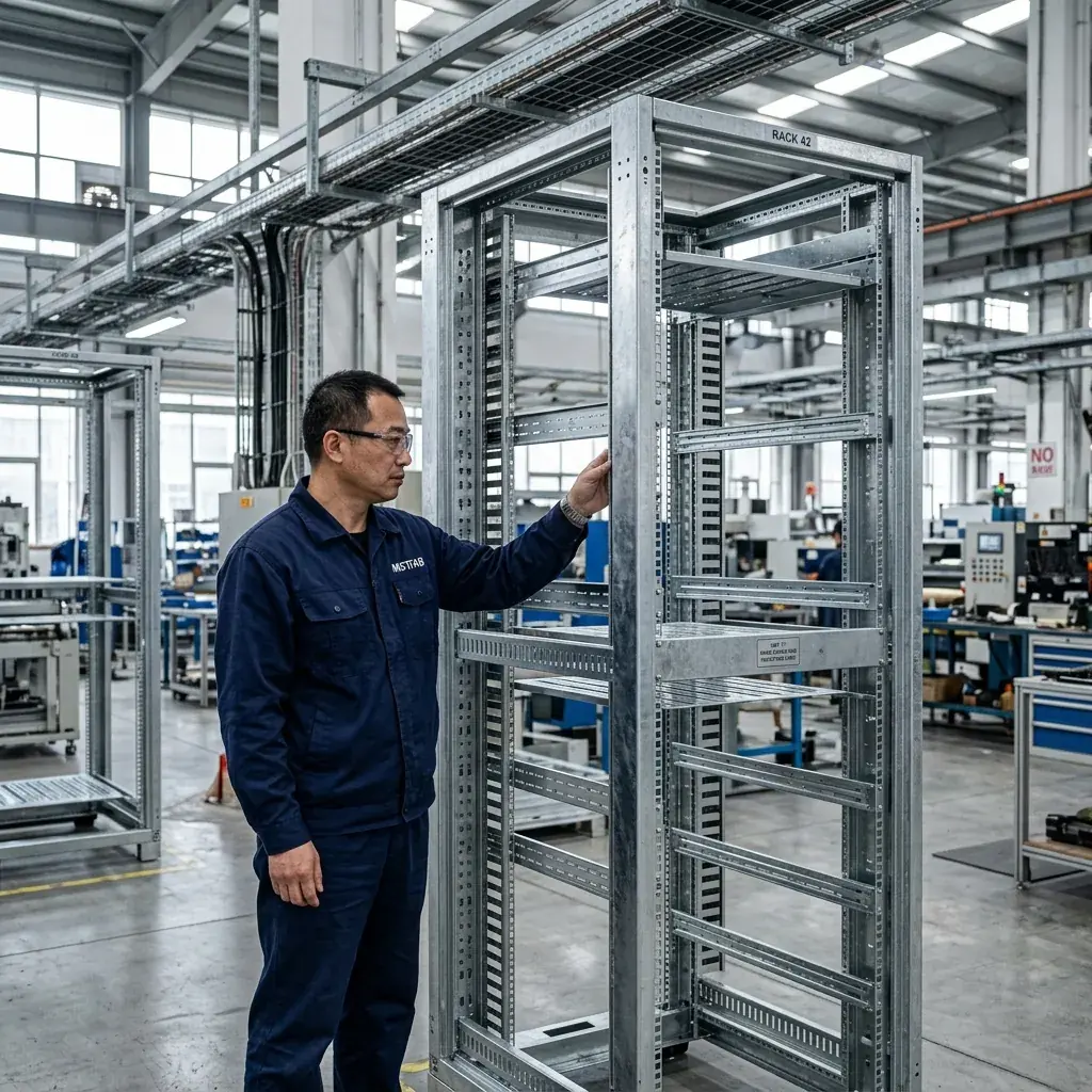
Control the usable envelope, not only the rail spacing.
The installed equipment needs a continuous route from the cabinet opening to its final position. Rails, doors, hinges, cable managers, shelves and rear accessories can each reduce that route. Put the dimensions below on the released drawing or interface schedule.
| Interface | Input to release | First-article evidence |
|---|---|---|
| Rail datum and pattern | Governing buyer requirement, left-right spacing, hole pattern, vertical reference, rail orientation and adjustment range. | Actual measurements tied to the drawing datums and revision. |
| Usable equipment depth | Front and rear reference planes, connector allowance, cable bend space, door hardware and rear accessories. | Depth measurements or a controlled fit gauge in the required cabinet state. |
| Equipment insertion | Largest device envelope, handle or ear projection, installation direction and temporary tool clearance. | Trial fit with the controlled component, representative sample or agreed gauge. |
| Shelves and vertical managers | Mounting pattern, adjustment range, loads, fasteners and conflict zones around equipment. | Installed location, hardware count, access and load-case record when specified. |
| Door and latch envelope | Opening angle, hinge projection, latch rods, stops, removable-panel route and site clearance. | Closed gap, latch operation, swing clearance and service-open photographs. |
| Base and site interface | Anchors, plinth or casters, lifting points, cable entry, center of gravity and shipping state. | Interface dimensions, assembly check and buyer-defined load or lifting evidence. |
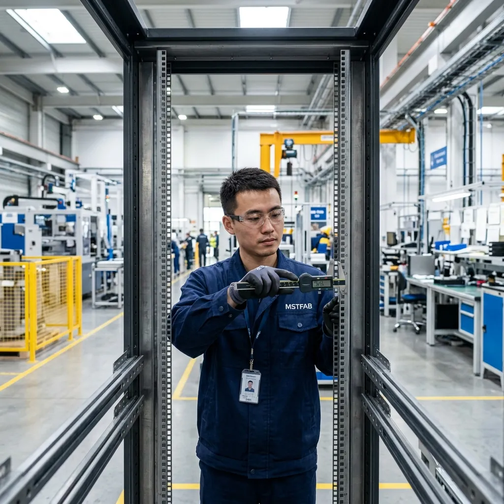
Review the cabinet while it is closed, operating, serviced and moved.
A static CAD view hides the moments when doors, trays, cable loops and equipment compete for the same space. Define the states that matter before flat patterns are released.
Confirm gaps, latch engagement, panel fit, cable clearance and equipment-to-door space.
Protect the intended air path, cable bend radii, filter area and access to indicators or controls.
Show door swing, tray travel, tool access, temporary cable movement and safe working space.
Prove that the largest replaceable item can leave without dismantling unrelated cabinet structure.
Control lifting, restraints, removable parts, center of gravity, anchoring and final assembly sequence.
Turn perforation into a controlled mechanical interface.
Perforation changes open area, stiffness, coating coverage and appearance. The system designer should define heat load, airflow direction and installed components. The fabricator can then review the physical openings and the metal left around them.
Inlet and exhaust zones
Identify intended flow direction, blocked zones and the components that must align with each opening.
Fan and filter interfaces
Freeze cutouts, fasteners, support, seal lands, removal path and filter service clearance.
Panel stiffness
Review dense perforation near bends, latches, hinges and structural edges before cutting.
Thermal evidence
Mechanical inspection confirms openings and fit; completed-system thermal validation remains buyer owned.

Release load cases, bonding interfaces and visible surfaces together.
A welded cabinet, bolted frame and flat-pack system behave differently in production, transport and field assembly. The drawing should state which configuration is being evaluated and who accepts the result.
| Decision | Controlled input | Useful evidence |
|---|---|---|
| Installed loads | Equipment masses, shelf loads, center of gravity, restraint points and acceptance criteria. | Dimension checks, assembly records and specified load-test record where required. |
| Lifting and anchoring | Lifting state, hardware, anchor layout, base flatness and responsible engineering authority. | Interface inspection and buyer-approved verification plan. |
| Bonding features | Studs, removable-panel straps, masked contact zones and buyer-selected hardware. | Location, thread, mask and hardware inspection; system continuity remains buyer controlled. |
| Finish and appearance | Pretreatment, color, texture, gloss, masks, visible zones and handling limits. | Approved sample or method, finish checks and protected-surface review. |
| Partner processes | Required processor controls, certificates, tests and incoming acceptance. | Purchase specification and returned records when contractually required. |
Process boundary: selected finishing processes may be completed by qualified long-term partners. The approved specification and required acceptance evidence still belong to the controlled order package.
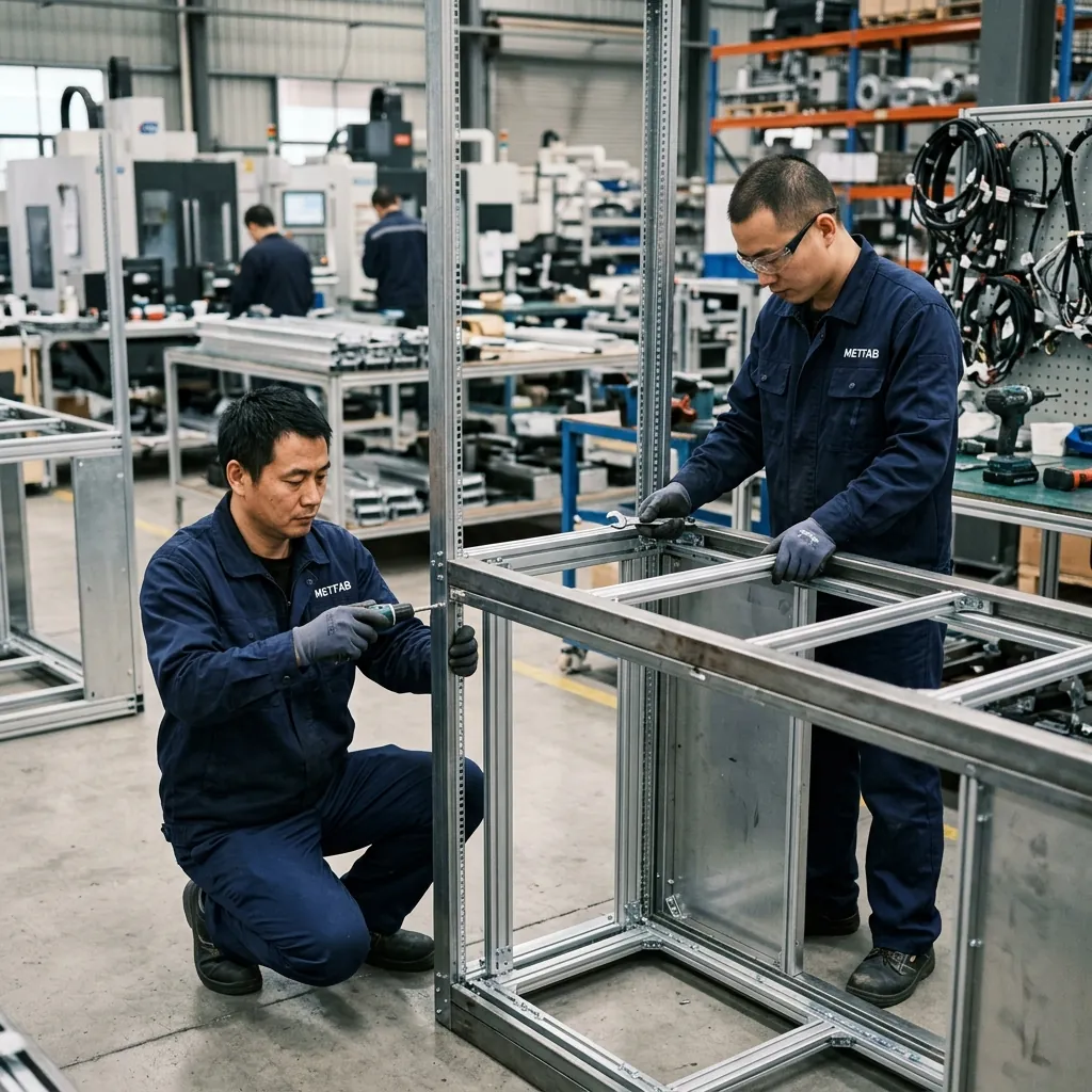
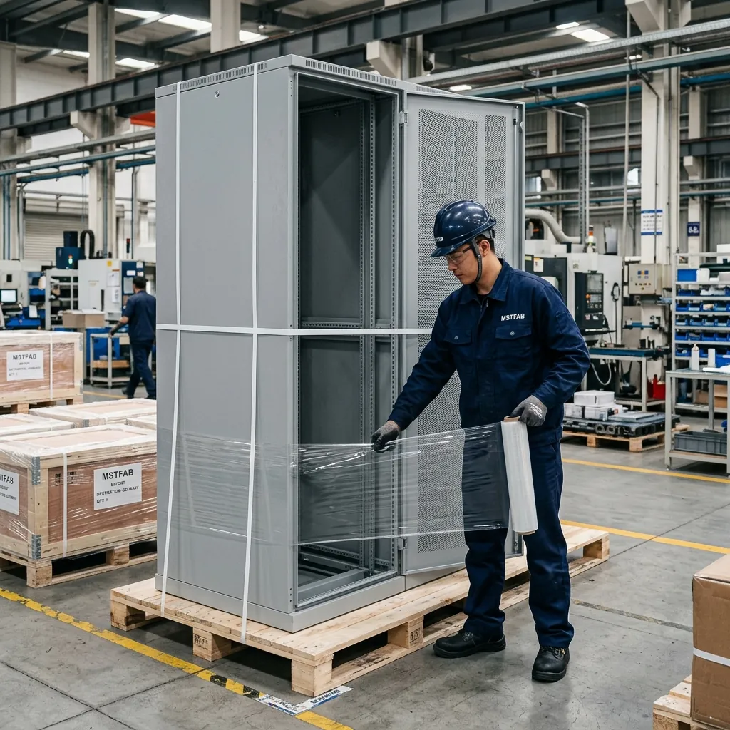
Build an evidence trail the next assembler can use.
Freeze inputs
Confirm revision, rack interfaces, equipment envelopes, loads, material, finish and quantities.
Review DFM
Close bend, weld, perforation, hardware, access and assembly questions in writing.
Build FAI
Use the production-intent route and preserve traceability to the released package.
Verify states
Inspect CTQs and agreed closed, service, removal and shipping configurations.
Release repeat build
Close deviations and carry the accepted baseline into recurring production.
Send one cabinet baseline an engineer can review.
MSTFAB does not publish one MOQ, lead time or tolerance for every network cabinet. Feasible values depend on size, material, construction, tooling, welding, hardware, finishing route, inspection, packing and quantity.
- STEP or STP assembly and controlled 2D PDF
- DXF or DWG data when buyer controlled
- Rack interface, datums and usable depth
- Equipment models, masses and keep-out zones
- Door, tray and removal states
- Cable entry and bend-clearance requirements
- Airflow openings and component interfaces
- Loads, lifting, base and anchor details
- Material, finish, masks and cosmetic zones
- FAI, packing, quantity and destination
Network cabinet rack-interface questions.
What does MSTFAB supply for a network cabinet project?
MSTFAB supplies drawing-based fabricated mechanical parts and empty enclosure shells, including frames, doors, side panels, roofs, bases, rail brackets, gland plates and mounting parts. Servers, switches, power distribution units, fans, wiring, software, system integration and final product certification remain with the buyer or responsible OEM unless an approved quotation states otherwise.
Which files should a network cabinet RFQ include?
Send a STEP or STP assembly, a controlled 2D PDF, and DXF or DWG data when buyer controlled. Include the drawing revision, rack interface, usable depth, installed equipment envelopes, door and service states, cable entry, airflow openings, material, finish, loads, quantities, inspection requirements and shipping configuration.
Is a 19-inch rack description enough for fabrication?
No. The buyer should identify the governing interface and place the released rail hole pattern, spacing, vertical reference, usable depth, adjustment range and equipment clearances on the controlled drawing. A product label or sales image is not a manufacturing baseline.
Who owns airflow and thermal performance?
The OEM or system designer owns equipment heat load, airflow direction, fan or cooling-unit selection, controls and completed-system thermal validation. The shell fabricator can produce drawing-defined perforations, fan openings, filter frames and mechanical interfaces and can inspect those physical features.
What first-article evidence is useful for a network cabinet?
Useful evidence may include material identification, a ballooned dimension report for rack and interface CTQs, rail alignment, door and latch operation, hardware count, opening dimensions, finish checks, assembly-state photographs and packing release. The buyer should name the required evidence before quotation.
Does MSTFAB publish one MOQ, lead time or tolerance for every network cabinet?
No. Quantity, lead time and feasible tolerances depend on cabinet size, material, frame construction, tooling, welding, hardware, finishing route, inspection scope, shipping method and order volume. They are confirmed from the released package and project quotation.
Ready to release the cabinet as an equipment interface?
Send the current assembly, controlled drawings, equipment schedule, cabinet states, loads, finish, inspection scope, quantities and destination. MSTFAB will review the drawing-based mechanical scope and return project-specific manufacturing questions.
 WeChat Contact
 WhatsApp Me Directly