
Quick answer: To avoid sheet metal assembly problems, define which features locate the part, how their tolerances combine and whether acceptance applies before or after forming, welding and finishing. Agree the inspection method for critical interfaces. A machine positioning specification is not a guarantee of finished-part accuracy.
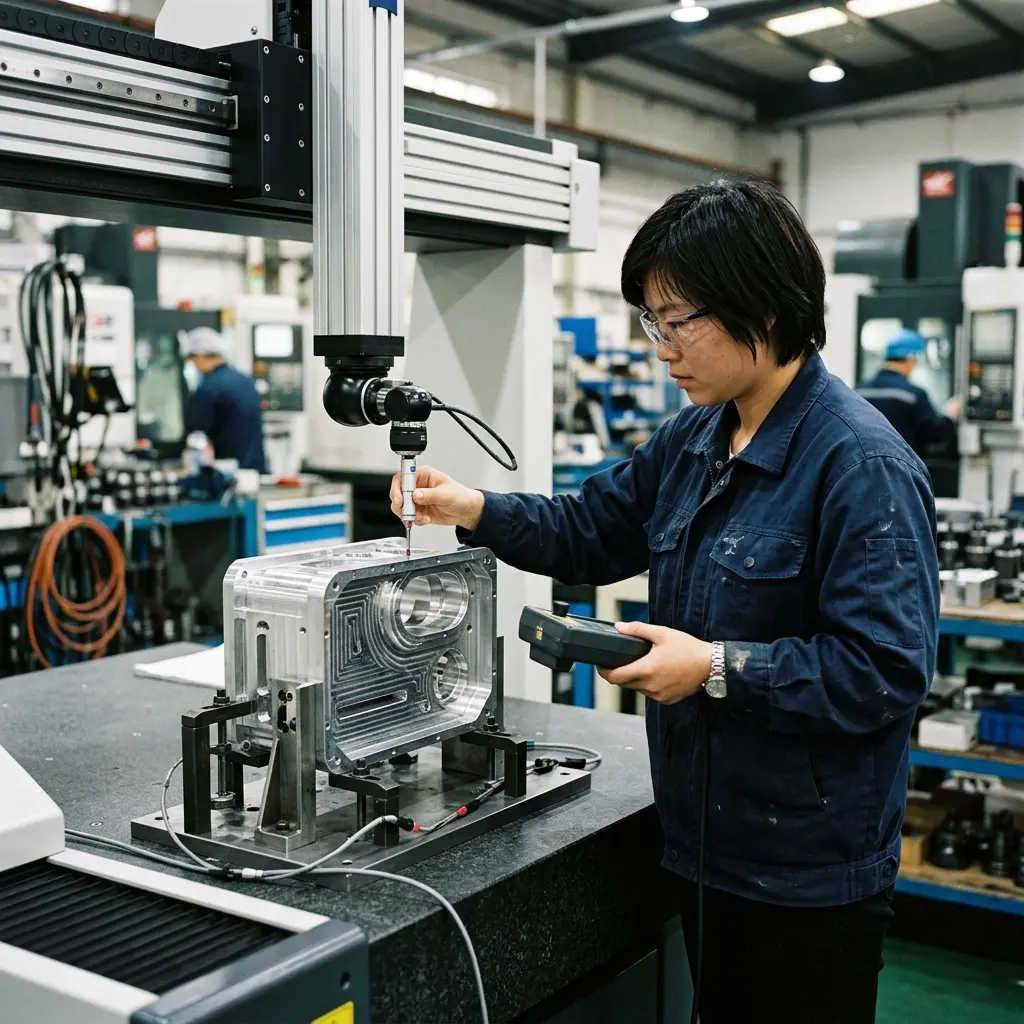
Start with the interface that must fit
Identify the mating part, mounting face and locating features before assigning tighter tolerances. A cabinet door, removable mounting plate and folded electronics cover have different functional requirements. Overall size alone does not explain whether a hole pattern will align or a cover will close.
Supply the assembly model together with controlled part drawings. Mark critical clearances and the measurement condition. If a plate is inspected while clamped but must fit freely in the cabinet, the inspection result may not answer the assembly question.
Check how tolerances accumulate
Two parts can each meet their individual drawing and still fail to fit if the combined limits leave insufficient clearance. Review the complete dimensional path between the locating features, not just the dimensions that are convenient to measure.
Illustrative example: an opening specified as 100.0 ±0.3 mm has a minimum width of 99.7 mm. A mating panel specified as 99.4 ±0.3 mm has a maximum width of 99.7 mm. At those limits, the total width clearance is zero. The example demonstrates a worst-case size comparison, not a recommended clearance. Coating, shape and alignment may introduce additional constraints.
Do not resolve this by quietly changing production dimensions. The design owner should approve a revised clearance, tolerance allocation or locating arrangement.
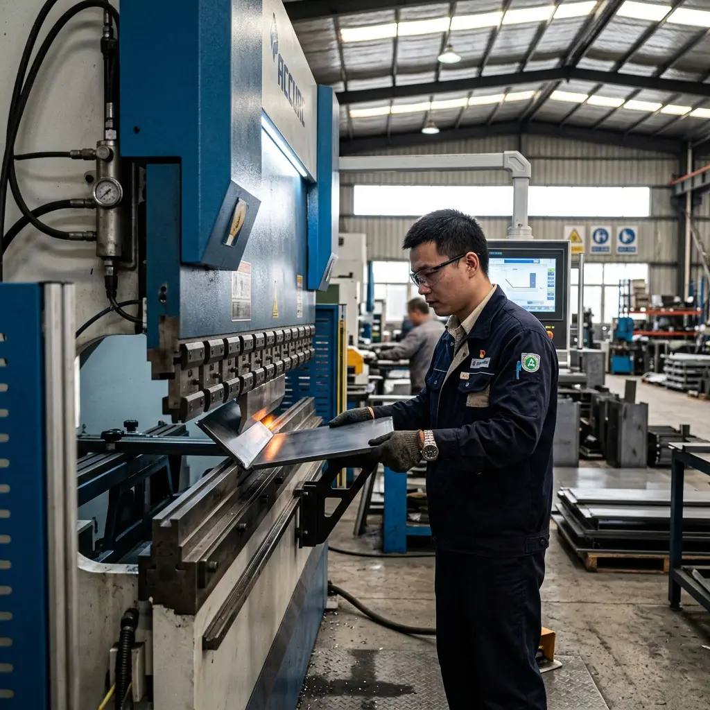
Separate formed dimensions from flat-pattern accuracy
After bending, check the angle, flange dimensions and feature locations that determine fit. A correctly cut blank does not establish that every dimension will remain acceptable after forming.
Bend allowance and deduction help establish developed blank geometry. They are not substitutes for controlling the finished bend angle. The material and forming process need to be reviewed together. Use the bend radius guide for the inputs to discuss before releasing a flat pattern.
Inspect welded interfaces after the relevant operations
For a welded frame or enclosure, define which mounting features and faces must remain in relationship after welding. Agree the inspection setup, support condition and sequence. A visual weld inspection and a dimensional fit check answer different questions; neither should be described as eliminating all distortion.
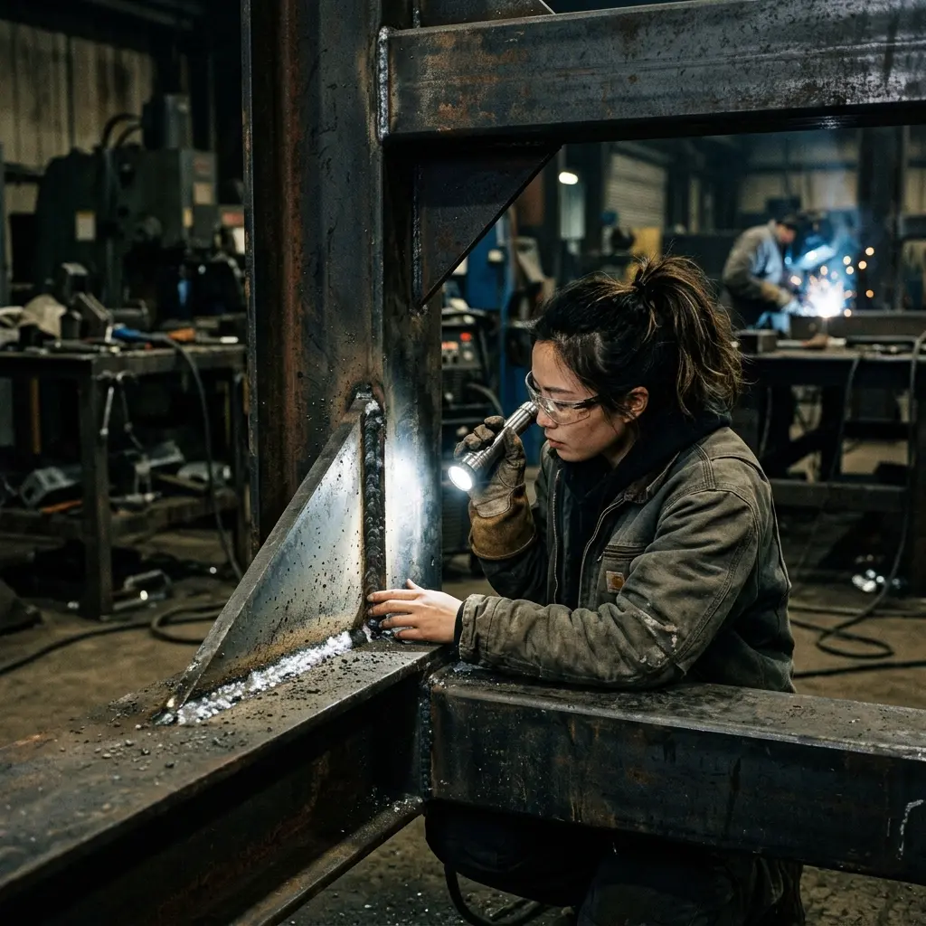
If the assembly uses studs or brackets, specify their location, orientation and finished projection. Confirm whether an approved mating template or shell will be available for the first-article check. Do not force a mismatched assembly together and call the result acceptable without the buyer’s disposition.
Use the finished condition for close interfaces
State whether critical hole sizes, gaps and threaded features are accepted before or after finishing. Identify masked areas and visible faces. If a bare assembly fits but the finished one does not, the drawing may have left an important condition unresolved.
Protection ratings and equipment certification are separate requirements. Dimensional inspection alone does not certify ingress protection, electrical safety or the complete equipment.
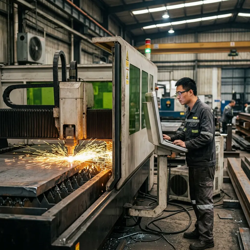
Agree evidence rather than a universal precision promise
| Assembly question | Define on the drawing or order | Useful evidence |
|---|---|---|
| Does the hole pattern align? | Functional references, size and location requirements | Agreed dimensional report or fit-template result |
| Does the cover close? | Finished gaps, locating faces and hardware configuration | Mechanical fit check in the specified condition |
| Is the welded structure acceptable? | Critical faces and mounting interfaces after welding | Post-weld measurements using the agreed setup |
| Does finishing affect assembly? | Masking, final hole requirements and inspection stage | Post-finish dimensional and appearance checks |
| Can the next batch be compared? | Part number, revision and approved deviations | Traceable first-article and repeat-order records |
Specify the required records before ordering. These are possible acceptance arrangements, not a claim that every order includes every measurement. Tighter tolerances may require a different process or inspection approach; agree feasibility for the actual geometry.

What to do when the first article does not fit
- Confirm the drawing and mating-part revisions.
- Record the actual mismatch and inspection condition.
- Check whether the problem concerns size, location, shape or installation access.
- Obtain written disposition before rework or a design change.
- Update the controlled documents and repeat the relevant check.
Protect accepted parts during shipment, especially projecting hardware and finished mating surfaces. Packing requirements should support the agreed condition on arrival rather than rely on a generic promise about export packaging.
Request a drawing-based fabrication review
MSTFAB manufactures sheet metal parts and empty mechanical enclosure shells to agreed drawings. Send the model, PDF, mating geometry, material, finish, quantity and critical inspection requirements. Manufacturing feasibility, delivery timing and records are agreed for the project. The buyer remains responsible for final design performance and completed-equipment validation.
Read the drawing interpretation guide to check the notation, or send your assembly requirements to MSTFAB.
 WeChat Contact
 WhatsApp Me Directly