
Quick answer: Read a sheet metal drawing in this order: revision and units, material and thickness, formed views and bend notes, hole and hardware callouts, then datums, tolerances and finish. Compare it with the assembly before requesting a production quote. A line style or a realistic-looking CAD model does not resolve a missing manufacturing instruction.
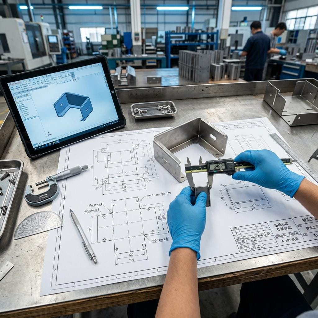
A sheet metal drawing checklist for buyers
This guide explains how to interpret a print, rather than which files to attach to an RFQ. Start with the checks below and send unresolved questions to the drawing owner. Do not quietly fill in the blanks on their behalf.
| Drawing area | Check | Clarify if missing |
|---|---|---|
| Title block | Part number, revision, units and sheet count | Which revision controls the quotation and production? |
| Material note | Grade, thickness, condition and applicable specification | Is a substitute allowed, and who approves it? |
| Formed views | Projection, bend direction, inside radius and finished angle | Are dimensions measured inside, outside or to a theoretical corner? |
| Holes and hardware | Quantity, size, location, thread and installation side | Are holes cut, tapped, countersunk or fitted with inserts? |
| Inspection notes | Datums, individual tolerances and measurement condition | Is acceptance checked before or after coating? |
1. Confirm the title block before reading dimensions
Check that the PDF, STEP model and purchase order identify the same part and revision. Look for the unit note before reading a number: a dimension of 25 is not meaningful until the drawing establishes millimeters or inches. Do not measure a screenshot to recover an omitted dimension.
A material name alone is often incomplete. An aluminum part may also need an alloy and temper; a steel part may need a grade, delivery condition and coating specification. A stainless steel designation does not, by itself, certify a part for medical or food-contact use. Those requirements belong in the agreed specification.
For a folded component, the starting sheet has a nominal thickness. Added plates, welded bosses, inserts and formed features can create different local sections. Ask how the feature is constructed instead of assuming that every thickness change requires a fully machined part.
2. Separate formed views, hidden lines and bend notes
Use the projection symbol and view labels to establish orientation. A dashed line can show an edge hidden behind another surface; it is not automatically a bend line. Flat-pattern bend lines follow the drawing or CAD export convention. Confirm their meaning from the legend, bend notes and formed views.
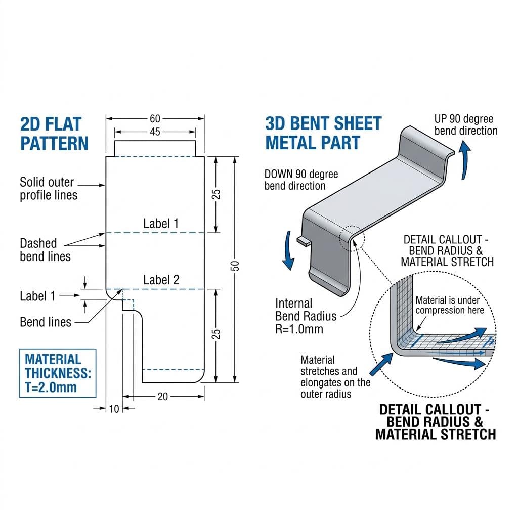
For each bend, identify the inside radius, final angle and direction from the specified viewing side. An angle may describe the included angle between flanges or the rotation from flat. If the convention is unclear, ask for a section or annotated view. The drawing should describe the finished part, not leave the operator to guess from the word “UP.”
Inside dimensions, outside dimensions and dimensions to a virtual sharp corner are not interchangeable. For a U-shaped cover, check whether the width is the clear opening or the overall outside size. For radius selection and flat-pattern calculations, see the sheet metal bend radius guide.
3. Read hole and hardware callouts as manufacturing instructions
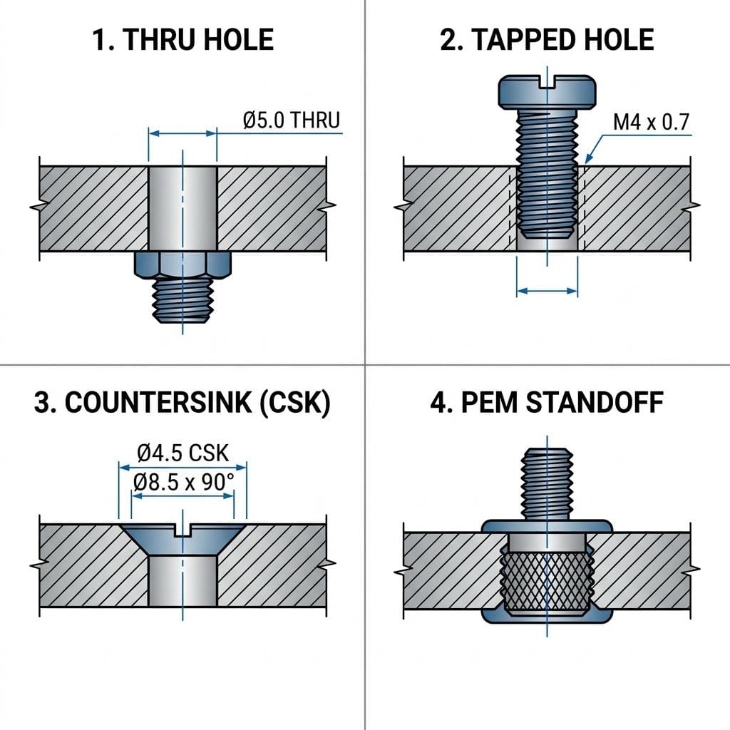
| Example | Meaning | Buyer check |
|---|---|---|
| Ø5 THRU | A nominal 5 mm through-hole, when drawing units are mm | Confirm quantity, position and applicable size tolerance. |
| M4 × 0.7 | A metric thread with 4 mm nominal diameter and 0.7 mm pitch | Confirm thread class, usable depth and whether the thread is tapped or supplied by hardware. |
| CSK | A countersunk feature for a specified head geometry | Specify diameter or depth, included angle and side. Thin sheet may need a different construction. |
| CBORE | A flat-bottomed recess | Check recess depth against available material thickness. |
| Self-clinching nut or standoff | A separate installed fastener | Specify the full part designation, orientation and supplier installation requirements. |
A circle in a front view does not tell you all of this. Read the note and section view together. For a handed pair of panels, confirm the insertion side: an otherwise correct standoff on the wrong face can stop assembly.
4. Read tolerances from functional references
A dimension of 150 ±0.1 mm allows a size from 149.9 to 150.1 mm. It does not automatically control flatness, perpendicularity or the position of every hole. Those requirements need their own applicable drawing controls.
Read datum references in the specified order. A hole pattern located from a mounting face and two locating features can serve a different assembly purpose from a chain of edge-to-edge dimensions. Ask which surfaces locate the component in the final assembly and whether they remain accessible for inspection.
Apply the general tolerance standard and class only when the drawing or agreed specification invokes them. Do not assume an unstated ISO tolerance class. Likewise, a supplier’s generic capability table is not acceptance criteria for your part. Thickness, bend length, material, geometry and the measurement setup all affect what can be agreed.
Worked example: reviewing a folded enclosure bracket
Suppose a drawing specifies a 2 mm sheet, a 90-degree flange and two mounting holes. These are illustrative inputs, not an approved production design. Before comparing quotes, resolve four questions:
- Is the material grade and condition stated, or does the drawing only say “steel”?
- Does the flange dimension run to the inside face, outside face or virtual corner?
- Are both holes located from the mounting datums, and is their size acceptable after finishing?
- Does the mating part have enough clearance for the bend, fastener head and tool access?
If the PDF says revision C but the STEP file represents revision B, stop and resolve the conflict. A cheaper quote against the wrong geometry is not a saving.
5. Agree on finish and inspection evidence
Define visible faces, coating requirements, masked threads, protected contact areas and the condition in which dimensions are accepted. Do not treat dimensional accuracy as proof of an enclosure’s IP rating. Any required ingress protection or completed-equipment approval needs its own agreed validation route.
| Question | Useful record |
|---|---|
| Did everyone use the same revision? | Approved drawing list tied to the order and part numbers |
| Were critical features measured in the right condition? | Agreed first-article check sheet showing datums and pre- or post-finish condition |
| Does the part fit its interface? | Mechanical fit check using an approved mating part, template or fixture |
| Are deviations accepted? | Written disposition identifying the affected feature and quantity |
Drawing questions buyers often ask
Is a STEP model enough to manufacture the part?
It can define geometry, but may not communicate material, threads, finish, tolerances or inspection requirements. Supply a controlled drawing or an agreed specification that covers those details.
Does a dashed line always mean a fold?
No. It may indicate a hidden edge. Read the view, legend and bend notes before assigning a manufacturing operation.
Should I ask for the tightest tolerance everywhere?
No. Identify the features that determine fit and function, and agree achievable controls for those features. Unnecessary tight tolerances can add setup and inspection work without improving the assembly.
Send a drawing for fabrication review
MSTFAB fabricates drawing-based sheet metal parts and empty enclosure shells. Share the revision-matched model and PDF, material, finish, quantity and the interfaces that must fit. We can review fabrication questions; the product owner remains responsible for the final design and equipment validation.
Use the RFQ file checklist to organize the package, or contact MSTFAB about your drawing.
Technical reference
ASME Y14.2: Line Conventions and Lettering describes the scope of engineering drawing line and lettering practices. Follow the standard and edition invoked by your drawing. This guide is a reading aid, not a substitute for that specification or engineering approval.
 WeChat Contact
 WhatsApp Me Directly