
Quick answer: The inside bend radius is the curve on the inside of a formed sheet metal bend. Choose it using the material grade and condition, thickness, grain direction, tooling and finished-part requirements. There is no single minimum radius that is safe for every steel, stainless steel or aluminum sheet. Confirm the radius and flat-pattern method with the fabricator before releasing the drawing.
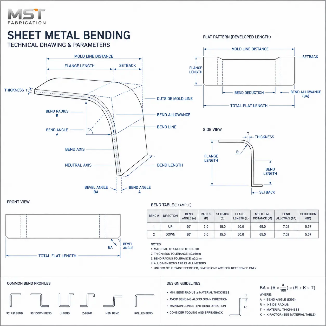
What is the difference between inside and outside bend radius?
The inside radius is measured at the concave face of the bend. The outside radius is approximately the inside radius plus the sheet thickness in a simplified constant-thickness model. Neither should be confused with the radius of a drawn corner in the flat profile.
A bend also has tangent points where the straight flanges meet the curved region. A dimension to a tangent point differs from one to the theoretical sharp intersection of the flange faces. Establish that convention before calculating a blank or comparing inspection results.
Why does bend radius matter for enclosure and bracket fit?
A radius occupies space inside an enclosure and changes the developed length of the blank. A larger radius may interfere with a mounting plate or mating bracket even when the overall dimensions remain unchanged. A smaller radius may be harder to form without cracking or surface damage.
Review the bend together with flange length, hole position, fastener clearance and visible surfaces. The goal is a part that fits after bending and finishing, not simply a flat pattern that opens successfully in CAD.
How to choose a bend radius without a misleading universal chart
Using a radius near the sheet thickness is sometimes a preliminary design assumption. It is not a production rule. Obtain the material producer’s bending recommendations for the actual grade and condition, then have the fabricator review the proposed tooling and geometry.
| Material | Information to supply | What to resolve |
|---|---|---|
| Carbon steel | Grade, thickness and delivery condition | Do not apply a mild-steel assumption to a higher-strength grade. |
| Stainless steel | Grade, condition, thickness and cosmetic face | Review forming behavior, springback and tooling marks for the specified finish. |
| Aluminum | Alloy, temper, thickness and rolling direction | Do not treat different alloys or tempers as interchangeable. |
| Pre-coated sheet | Base grade and coating specification | Assess the bend and the coating condition; a sound substrate does not guarantee an undamaged finish. |
For steel-specific background, SSAB’s bending guidance explains how material and tooling influence the result. Its recommendations are product-specific, not universal values for unrelated sheet grades.
Radius, tooling and springback are related, but not identical
In air bending, the final radius is influenced by the material and tooling combination; it should not automatically be assumed to equal the punch tip radius. Bottoming and coining use different contact and force conditions. Confirm the proposed method rather than transferring one process’s settings to another.
Springback is the elastic recovery after forming load is removed. Define the required final angle on the drawing. The fabricator determines the process compensation needed to reach that angle; the buyer should not replace a finished-angle requirement with an unverified machine setting.
Bend allowance and K-factor: a worked calculation
Bend allowance is the developed length assigned to the curved bend region. K-factor represents the neutral-axis position as a fraction of sheet thickness. For a simple circular-bend model:
BA = θ × (R + K × T)
- BA: bend allowance
- θ: angle through which the material bends, in radians
- R: inside bend radius
- T: sheet thickness
- K: assumed or validated K-factor
Illustrative example only: with a 90-degree bend from flat, R = 2 mm, T = 2 mm and an assumed K = 0.40, BA = (π/2) × (2 + 0.40 × 2), or approximately 4.40 mm. This demonstrates the arithmetic; it does not establish a suitable K-factor or minimum radius for your material.
If the two straight lengths are measured to the tangent points, their sum plus BA gives the developed length in this simplified example. Do not add BA directly to two outside dimensions measured to a virtual sharp corner. That convention requires the appropriate setback and bend deduction.
SOLIDWORKS’ bend-allowance explanation distinguishes these CAD inputs. Agree whether the buyer supplies a validated flat pattern or the fabricator develops it from the approved formed model. Avoid applying a second bend deduction to a blank that already includes it.
Check holes, flange length and reliefs around the bend
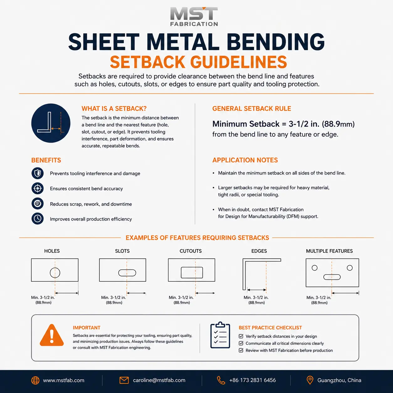
State whether a hole-to-bend distance is measured from the hole edge or center, and from the bend centerline or tangent. A distance without those references can be interpreted in several ways.
- Holes and slots: review whether they enter the deformation region. If distortion matters, discuss moving the feature, changing the geometry or adding a later operation.
- Short flanges: check support on the proposed die and tool access. A visually small flange is not necessarily formable with the selected tooling.
- Adjacent bends: review bend sequence and collision clearance, especially for deep returns and narrow channels.
- Reliefs: identify where the bend terminates near an edge or intersecting feature. Define the approved relief rather than leaving a tear-prone corner unresolved.
For a broader explanation of drawing notation and dimensional references, use the sheet metal drawing reading guide.
Keep the finished interface in the review
On a U-shaped cover, a radius change can alter the usable internal space. On a mounting bracket, the screw head or washer may clash with the bend. On a coated panel, the final clearance must include the specified finish. Include the mating geometry in the RFQ so these conflicts can be discussed before tooling is set up.
Radius, angle, flange size and overall width are separate inspection questions. An acceptable radius alone does not demonstrate correct assembly fit, load capacity or an enclosure protection rating.
What first-article evidence should you request?
| Feature | Define on the order or drawing | Possible agreed evidence |
|---|---|---|
| Inside radius | Target, tolerance and measurement method where critical | Recorded radius check using an agreed method |
| Bend angle and flange dimensions | Finished condition and functional references | First-article dimensional check sheet |
| Holes near bends | Final size, position and distortion acceptance | Post-forming feature measurements or approved fit template |
| Surface condition | Visible faces and permissible marks | Appearance check against an agreed sample or specification |
| Assembly interface | Mating part, fixture and acceptance criteria | Mechanical fit-check record |
These are records to specify, not a claim that every order includes every test. Keep the approved material, drawing revision and forming assumptions tied to repeat orders; a material or geometry change may require another review.
Request a drawing-based bending review
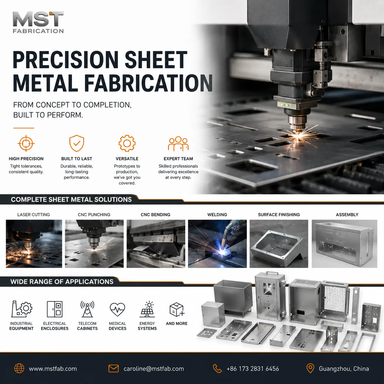
MSTFAB provides CNC sheet metal bending for drawing-based brackets, panels and empty enclosure shells. Send the formed STEP model, controlled PDF, material grade and condition, thickness, quantity, finish and critical interfaces. Identify any radius or dimension that cannot change.
Achievable tolerances, inspection records and delivery timing are agreed for the actual part. We do not assign one precision promise to every geometry or certify the buyer’s completed equipment.
Request a Sheet Metal Bending Quote
Share the material, thickness, finished geometry, quantity and critical fit requirements. Quotation and delivery timing depend on the agreed scope.
Frequently asked questions
Is an inside radius equal to thickness always acceptable?
No. It may be a starting assumption for some designs, but material grade, condition, direction and tooling can require a different value. Validate it before production.
Can I use one K-factor for every part?
Not without validating the relevant material and process range. A value that develops one part correctly may not transfer to a different material, thickness or forming setup.
Should the supplier change the radius to match available tooling?
Only through an agreed drawing or deviation approval. Check the effect on the mating space, developed length and critical dimensions before accepting the change.
Does changing the radius require a new flat pattern?
It can. Review the bend allowance or deduction and regenerate the affected geometry under revision control. Do not assume that an old DXF remains valid.
Scope: This guide concerns mechanical sheet metal fabrication. The product owner approves design performance and completed-equipment validation. Published examples and calculations are explanatory, not inspection evidence for a customer order.
 WeChat Contact
 WhatsApp Me Directly