
Quick Summary
A sheet metal prototype is the ultimate physical validation of your design. MSTFAB provides professional sheet metal fabrication prototype design reviews based on STEP and PDF files, detecting bending, welding, tolerances, and finishing conflicts to eliminate sample rework and prepare your design for seamless mass production.
A sheet metal enclosure is not just a digital box. It must protect, mount, open, close, wire, and survive real-world environments.
A clean CAD model looks perfect. But real fabrication introduces burrs, springback, welding distortion, coating thickness, and assembly interference. This is why a practical DFM review before prototype production is crucial to saving time, cost, and headaches.
What Is a Prototype Design Review in Sheet Metal Fabrication?
A prototype design review is a practical DFM (Design for Manufacturability) check before sample production. The purpose is not only to make a single sample, but to confirm whether the design can become a stable, repeatable production part. A sample made with heroic manual corrections on the factory floor is not manufacturing—it is a magic trick. And magic tricks do not scale.
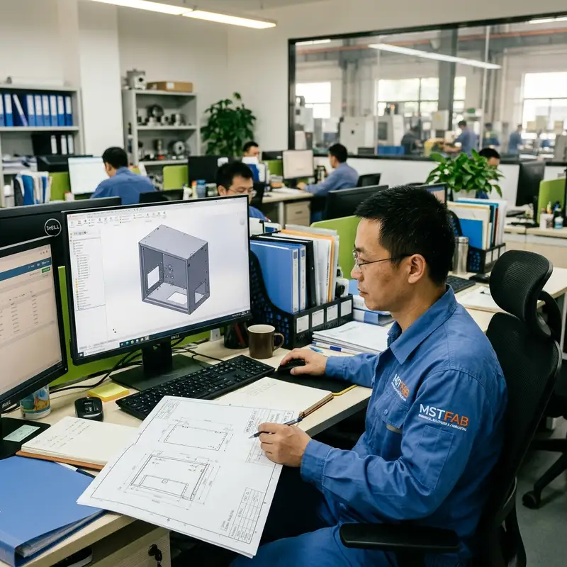
During the review, our engineering matrix audits drawings for custom sheet metal parts, including:
- Material selection and sheet thickness feasibility
- Bend sequences, bend radius, and flange access
- Hole-to-bend distance to avoid hole deformation
- Welding access and heat distortion risk
- Hardware insertion clearances (PEM studs, rivet nuts)
- Powder coating build-up on threads, hinges, and mating surfaces
- Assembly tolerances and export packaging protection
Why Review the Design Before Making a Prototype?
Many prototype problems start in the drawing. A design issue found before prototype production is a simple drawing update. A design issue found after fabrication is costly rework, shipping delays, and wasted material. That is not cost saving—that is cost relocation.
Common issues found during prototype reviews include:
- Material grades or sheet thicknesses not clearly defined (which increases sheet metal prototype costs).
- Inside bend radius too sharp, causing metal cracking during forming.
- Holes placed too close to bend lines, resulting in oval, distorted holes after bending.
- No clear callout for masking zones, leading to powder coat covering critical grounding studs.
- Blanket tight tolerances that drive up setup times and scrap rates unnecessarily.
By auditing the drawing first, we ensure the prototype answers a vital question: “Can this design be manufactured correctly, and can it be manufactured correctly again and again?”
Understanding Your Prototype Purpose
Not all prototypes serve the same purpose. Before quoting, it is essential to define the target scope of the sample:
| Prototype Type | Validation Focus | Finishing Level | Mass Production Alignment |
|---|---|---|---|
| Fit-Check Prototype | Hole alignment, overall size, mounting fit, clearances | Unfinished or raw metal | Low (focuses on geometry) |
| Appearance Prototype | Surface quality, powder coat texture, door gaps, aesthetics | Complete finishing, masking | Medium (focuses on aesthetics) |
| Functional Prototype | Door operation, cable routing, ventilation strength, load tests | Standard finish, hinges, locks | Medium-High |
| Production-Ready Prototype | Final production processes, custom hardware, export packing | Full finish, exact production specs | 100% Aligned |
DFM Checks: Bending, Hole Placement, and Welding
Bending and Tooling Clearances
Bending is where digital CAD models face physical limits. A design review verifies if return flanges have enough clearance for the press brake tooling. If a flange is too short, it cannot be held properly during forming. Ensuring smooth bending keeps assembly lines running without the need for hammers or manual adjustments. (For more details, check our sheet metal enclosure design guidelines).
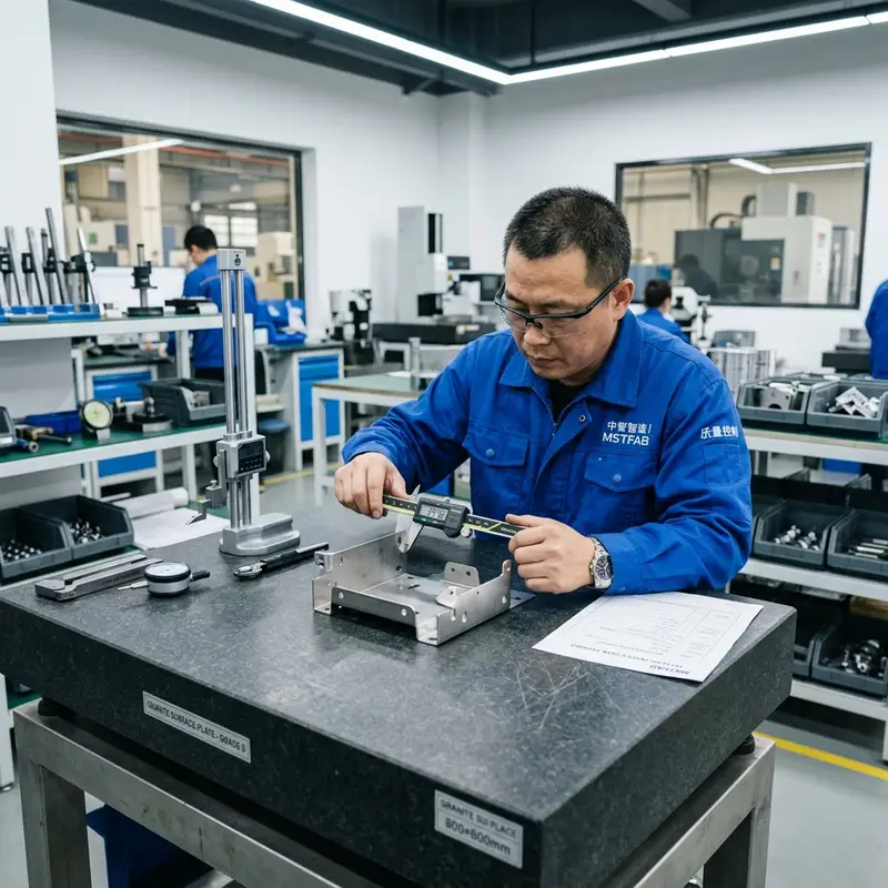
Hole and Cutout Placement
Holes placed too close to bend lines will stretch and deform during forming. If holes are deformed, fasteners will not fit and secondary drilling will be required. A professional review suggests moving critical holes away from the bend radius or using laser-cut relief cuts to isolate the deformation.
Welding Heat and Joint Alignment
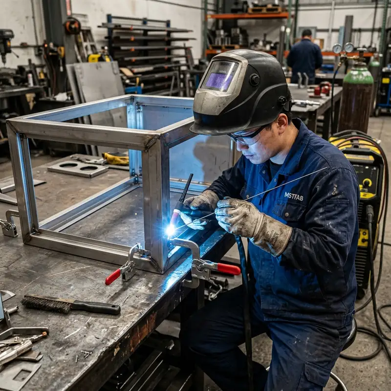
Welding adds heat, and heat moves metal. A design review checks joint fit-up, weld accessibility, and joint strength. If a prototype is heavily welded, we analyze the heat distortion risk. Selecting the correct weld type (TIG vs. MIG) and location helps prevent cabinet frames from twisting or losing squareness.
Surface Finishing: Powder Coating, Masking, and Grounding
Powder coating is not just color—it adds physical thickness (typically 60 to 120 microns). A hole that fits a pin perfectly before powder coating may become too tight afterward. Hinge pins, sliding tracks, and door gaps must all be designed with powder coating build-up in mind.
Furthermore, electrical enclosures and control cabinets require bare metal contact areas for grounding. A grounding point covered with powder coating is a decorative problem, not an electrical safety feature. Drawings must clearly specify masking zones, thread protection for PEM inserts, and conductive grounding points.
Final Assembly and Export Packaging
A prototype design review looks beyond the metal parts to the final assembly and transport. We review the assembly sequence: Can tools access the nuts? Is there enough room to route cables? If the assembly technician requires emotional support and a grinding wheel to put the box together, the prototype was not ready.
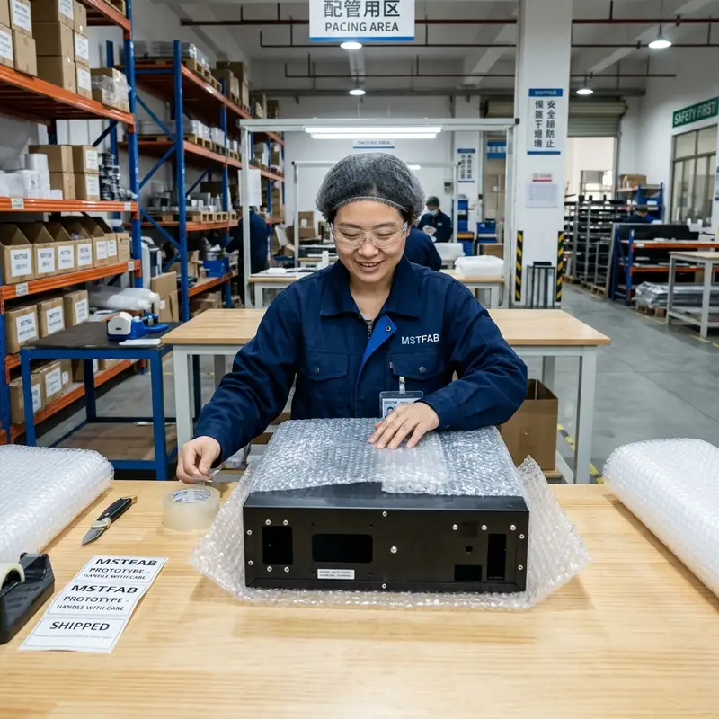
Finally, we check the packaging design. A beautiful prototype ruined by transit scratches or dented corners is useless. Our review ensures heavy-duty brackets, double-wall boxes, or custom wooden crates are included in the quote scope to protect your sample during international freight.
We Build the Armor, You Bring the Brain
At MSTFAB, we maintain clear boundaries to protect our customers’ intellectual property. We focus entirely on physical sheet metal fabrication—cutting, bending, welding, powder coating, and mechanical assembly. We do not require your proprietary electrical layouts, software logic, or system schematics. You bring the product design; we review and manufacture the sheet metal parts that protect it.
Request a Prototype Design Review & Quote
Avoid sample rework and procurement surprises. Send us your native 3D STEP files and 2D PDF drawings. Our engineering team will conduct a thorough DFM review, check tolerance compatibility, and prepare a detailed fabrication quotation.
Get a Prototype QuoteFAQ: Sheet Metal Prototype Design Review
What files do I need to send for a prototype design review?
For an accurate and effective review, please provide a native 3D STEP file (for geometry and bending clearances) and a 2D PDF drawing (defining materials, tolerances, hardware specs, masking areas, and powder coating colors). For help with drawing standards, see our sheet metal fabrication drawing requirements.
How do you prevent welding distortion on prototypes?
We review the joint design and weld locations to distribute heat evenly. We also use welding fixtures and suggest intermittent welds rather than continuous beads where structure allows, minimizing thermal twisting. For complex fabrications, see our guide on sheet metal enclosure fabrication from STEP files.
Can you review our design for future mass production during the prototype phase?
Yes. Every review we conduct considers the transition from prototype to mass production. We check if the design requires specialized custom tooling or manual corrections that could slow down batch production. For general DFM principles, check our DFM for sheet metal fabrication guide.
MSTFAB provides TIG and MIG sheet metal welding services for structural assemblies, cabinets, frames and OEM metal components.
 WeChat Contact
 WhatsApp Me Directly