DFM for Sheet Metal Fabrication: OEM Enclosure Design Review Guide
DFM for sheet metal fabrication means checking whether a drawing can be laser cut, CNC bent, welded, finished, inspected and packed without creating avoidable cost or fit problems. For OEM enclosure buyers, DFM is the quiet engineering step that prevents loud emails later.
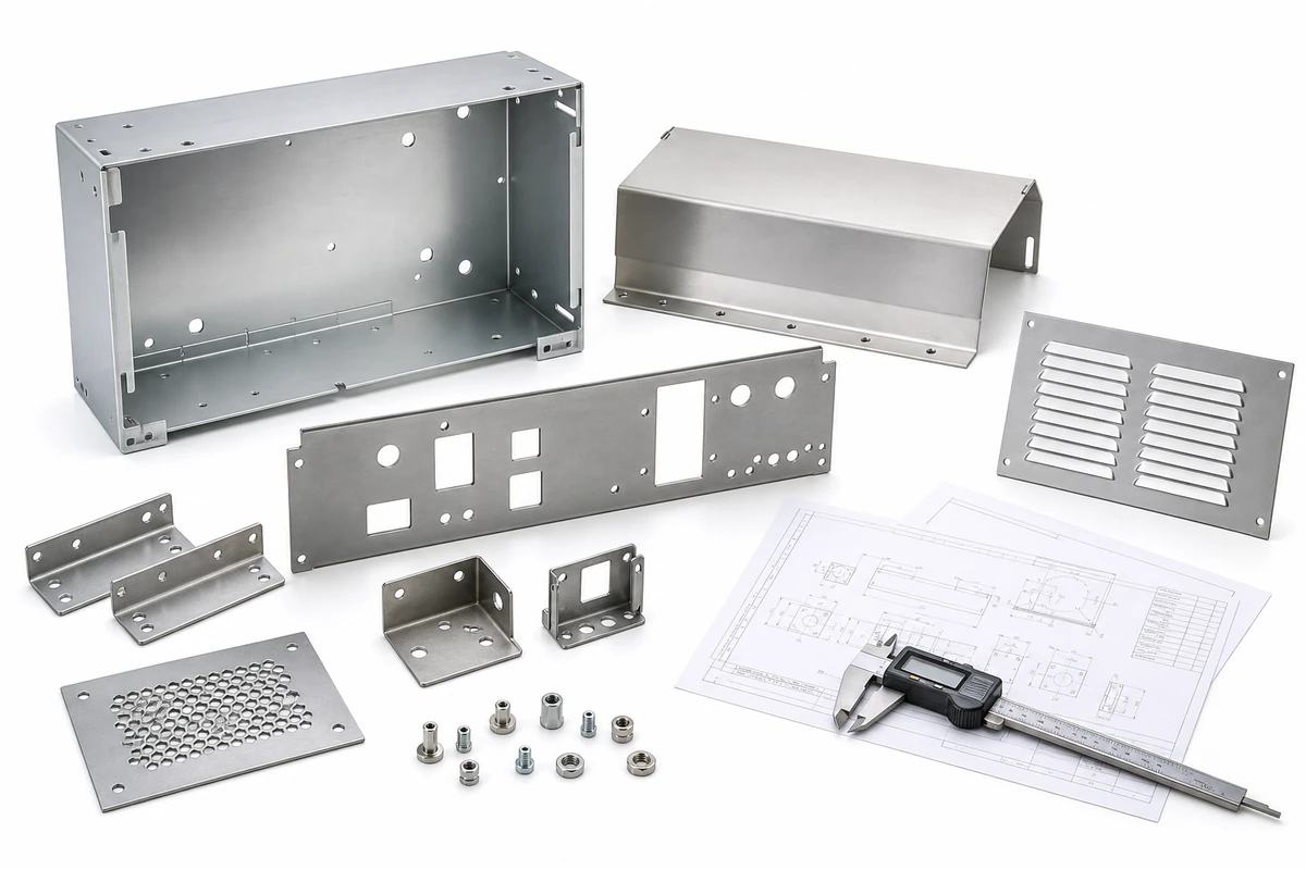
Short answer: a sheet metal DFM review checks material grade, thickness, bend radius, hole-to-bend distance, cutouts, PEM hardware positions, welding access, surface finish, tolerance stack-up and export packing before production. MSTFAB focuses on custom sheet metal enclosure shells, panels, covers, brackets, louver plates and chassis trays made from STEP, DXF and approved 2D drawings.
Scope note for buyers: MSTFAB manufactures semi-finished sheet metal enclosure parts. We do not position this page as an internal system build or installed device service. Your team controls later project integration; our job is to make the metal shells, panels, brackets and formed structures fit the drawing and survive the sourcing journey.
Why DFM Matters Before a Sheet Metal Enclosure Quote
Many sourcing problems start before the first sheet is cut. A buyer sends drawings, three suppliers quote quickly, and the lowest price looks attractive. Then the sample arrives with distorted holes, tight corners, scratched visible faces, a flange that cannot be formed cleanly, or a bracket that does not line up with the matching panel. The quote was fast. The problem is now faster.
DFM, or design for manufacturing, helps prevent that. It is not about changing the buyer’s product idea without permission. It is a practical review of whether the design can be manufactured repeatedly through real sheet metal processes. In custom sheet metal enclosure fabrication, the review connects CAD geometry with laser cutting, CNC bending, welding, hardware preparation, powder coating, inspection and packing.
For overseas OEM buyers, this is especially valuable because small drawing issues become expensive once parts ship internationally. A missing bend relief may create cracks. A hole too close to a bend may become oval. A coating thickness requirement may affect hardware fit. A visible face not marked on the drawing may be scratched during normal handling. DFM catches these risks while they are still cheap to discuss.
What MSTFAB Checks During DFM Review
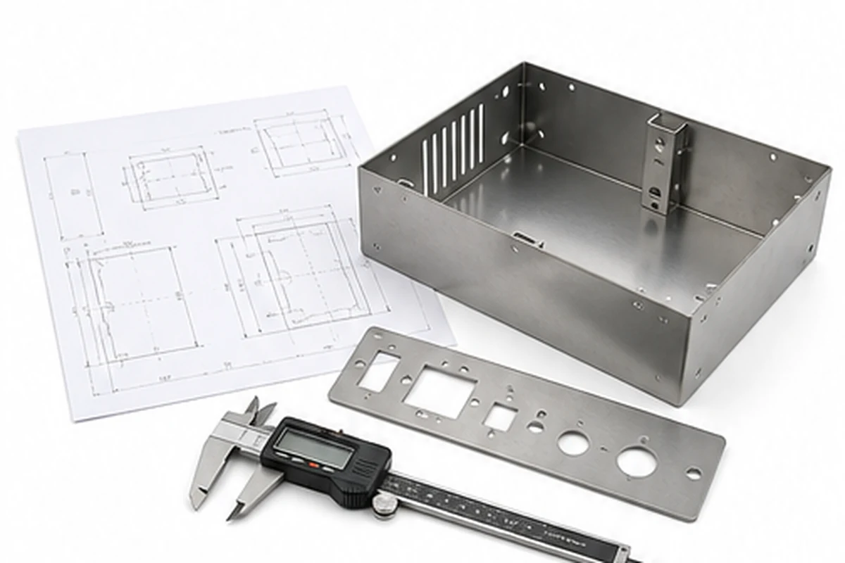
A good DFM review should be specific. It should not be a vague sentence like “we checked the drawing.” Checked for what? A procurement team needs useful comments: material risk, bend risk, hole risk, finish risk, tolerance risk and packing risk. DFM should turn uncertainty into clear decisions before production.
MSTFAB reviews drawing-based sheet metal projects from the perspective of manufacturability and repeatable fit. We look at whether the part can be cut, formed, reinforced, finished and packed according to the buyer’s requirements. The goal is not to make the drawing complicated. The goal is to make the physical part less surprising.
| DFM check | What can go wrong | What buyers should provide | MSTFAB review focus |
|---|---|---|---|
| Material and thickness | Wrong grade, hard bending, excess weight, unstable finish | Material grade, thickness, finish and environment | Material suitability for cutting, bending, welding and coating |
| Bend radius and flange length | Cracking, short flanges, poor angle control, tool interference | STEP, 2D drawing, bend direction and critical dimensions | Bend feasibility, bend relief and forming sequence |
| Hole-to-bend distance | Distorted holes, stretched slots, poor alignment | Critical holes, mating parts and tolerance notes | Cutout location relative to bend lines |
| Laser cut openings | Sharp internal corners, burr risk, weak bridges, poor vent stiffness | DXF, PDF drawing and edge requirements | Slot width, cutout size, corner radius and edge condition |
| PEM hardware | Wrong hole size, weak installation, wrong side, coating interference | Hardware type, install side, thread and location | Material thickness, hole prep and post-installation position |
| Surface finish | Scratches, coating buildup, color mismatch, blocked holes | Color, texture, visible face and protected areas | Finish compatibility and packing protection |
DFM Starts with a Clean RFQ Drawing Package
DFM review is only as good as the information sent to the supplier. A single screenshot is not enough. A helpful RFQ package includes STEP or STP files, DXF flat files if available, 2D PDF or DWG drawings, material grade, thickness, quantity, finish, critical tolerances, hardware notes, visible surface notes and packing requirements.
For custom sheet metal enclosure parts, context matters. Is the part an empty enclosure shell, door, cover, louver panel, back plate, bracket, rail or chassis tray? Which side faces the customer? Which holes align with another part? Which edges seal against foam or gasket later? Which dimensions must stay tight after bending or coating? Buyers do not need to write a novel, but a few notes can save a lot of production drama.
If the RFQ package is incomplete, the quote may look neat but hide risk. A supplier may assume standard tolerances, standard finish, standard packing and no special visible surface. Those assumptions are dangerous when the buyer expects something different. DFM helps turn assumptions into confirmed requirements.
Send these files
- STEP or STP model
- 2D PDF or DWG drawing
- DXF flat pattern if approved
- Current revision number
Define the part
- Material and thickness
- Finish and visible side
- Critical tolerances
- Hardware locations
Control the project risk
- Bend direction
- Surface protection
- Inspection evidence
- Export packing method
Laser Cutting DFM: Holes, Slots, Vents and Cutouts
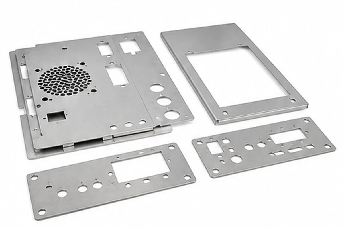
Laser cutting gives sheet metal fabrication its flexibility. It creates the profile, connector openings, mounting holes, louver patterns, cable gland openings, slots and panel shapes. But flexible does not mean magic. Very small holes, narrow slots, sharp internal corners and dense perforation areas can create cost, burr and distortion issues.
For enclosure panels, DFM should check minimum hole size, slot width, corner radius, distance between features, edge quality, cut direction where relevant and whether the part will be bent after cutting. A hole may be perfect while flat and ugly after forming if it sits too close to the bend line. That is not a laser problem only; it is a process route problem.
MSTFAB reviews laser cut enclosure panels with the next processes in mind. If the panel will be bent, welded, powder coated or packed with other parts, the laser file should support that route. This is why DFM belongs before production, not after the first sample has already proven the drawing was optimistic.
CNC Bending DFM: Bend Radius, Flanges and Forming Sequence
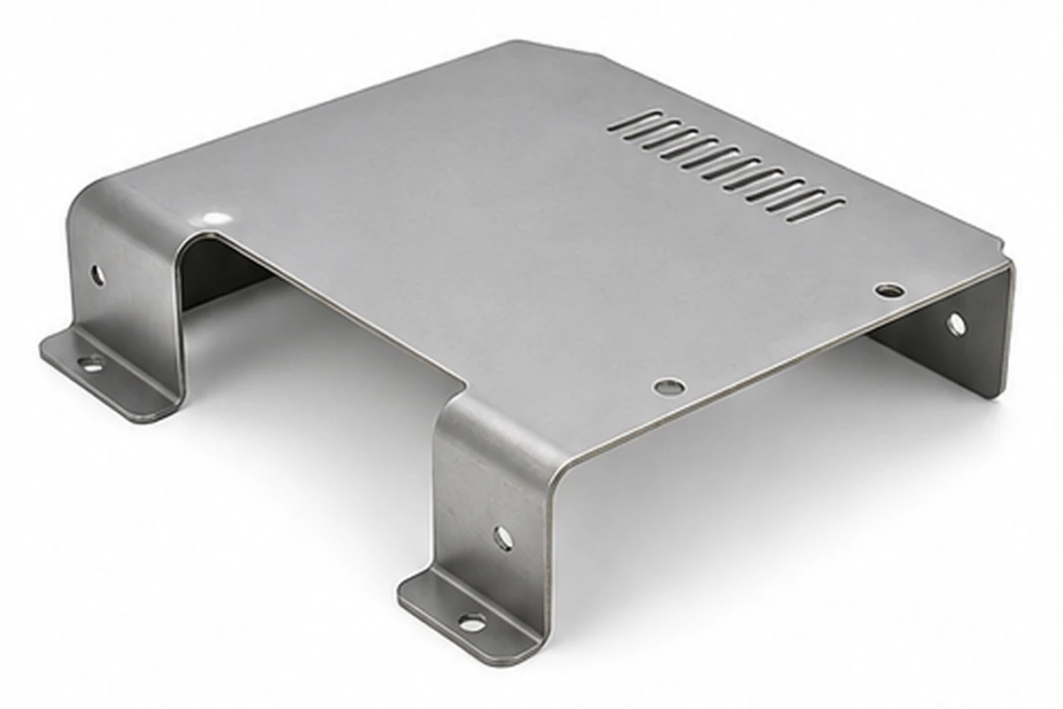
CNC bending turns flat sheet into useful three-dimensional enclosure parts. Bends add stiffness, create side walls, form covers and make chassis trays possible. A flat sheet becomes a shell because the bends are planned correctly. A flat sheet becomes scrap when the bends are guessed.
Important bending checks include inside bend radius, material thickness, flange length, bend relief, hole-to-bend distance, grain direction, tooling clearance and bend sequence. If the flange is too short, the press brake may not grip it properly. If a part has too many opposing bends, it may collide with tooling. If a cutout is too close to a bend, it may distort.
For custom sheet metal enclosure shells and covers, MSTFAB checks whether bends are realistic before confirming production. This helps buyers avoid parts that look easy in CAD but behave badly in metal. CAD is polite. Sheet metal is honest.
Hole-to-Bend Distance: Small Detail, Big Fit Problem
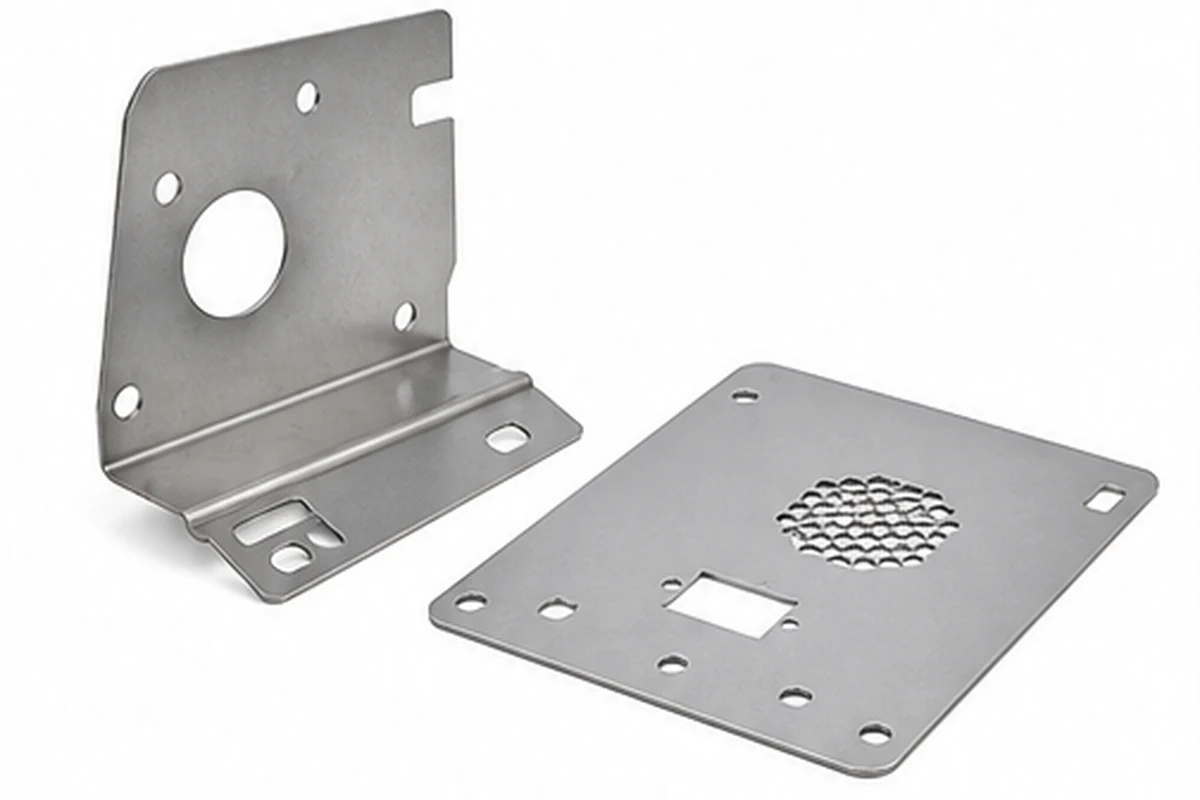
Hole-to-bend distance is one of the most common sheet metal DFM issues. If a hole, slot or rectangular opening sits too close to a bend line, it can stretch, deform or shift during forming. The drawing may show a perfect circle; the real part may politely disagree.
This matters for enclosure projects because holes often locate hinges, latch plates, mounting rails, brackets, screws or later project interfaces. If those holes move, the buyer’s next process becomes slower. Sorting, drilling, filing or rejecting parts is not a production plan. It is a rescue mission.
DFM review should identify critical holes near bends and suggest practical adjustments where possible. Sometimes the hole moves slightly. Sometimes a slot changes shape. Sometimes bend relief is added. Sometimes the tolerance requirement needs to be tied to a practical datum. The point is to find the issue while changing a drawing is still easier than changing a batch of metal.
PEM Hardware DFM for Sheet Metal Enclosure Parts
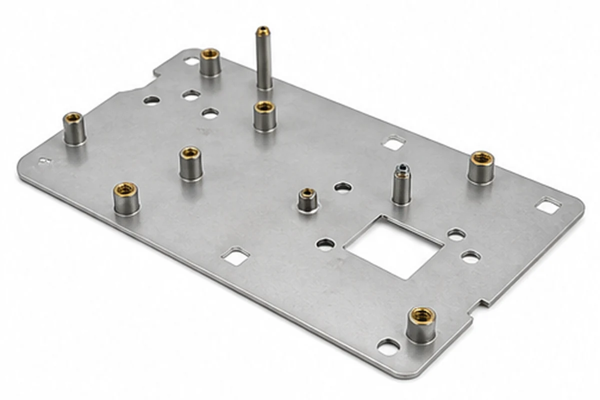
PEM nuts, standoffs, studs and threaded inserts are common in sheet metal enclosure projects. They make later fit-up cleaner when the location is correct and the material supports the hardware. They become a very small but very annoying problem when the hole size, material thickness or installation side is wrong.
Buyers should define the hardware type, thread, installation side, hole preparation, quantity, torque or pull-out requirement if relevant, and whether the hardware area will be powder coated. Coating can affect thread or contact surfaces. Thin material may not support a selected fastener. A standoff on the wrong side of the panel can make a good drawing feel personally betrayed.
MSTFAB checks PEM hardware locations and material suitability during DFM review. For OEM enclosure panels, mounting plates and brackets, this helps keep holes, inserts and formed geometry aligned with the approved drawing.
Welding DFM: Heat, Fixtures and Distortion Control
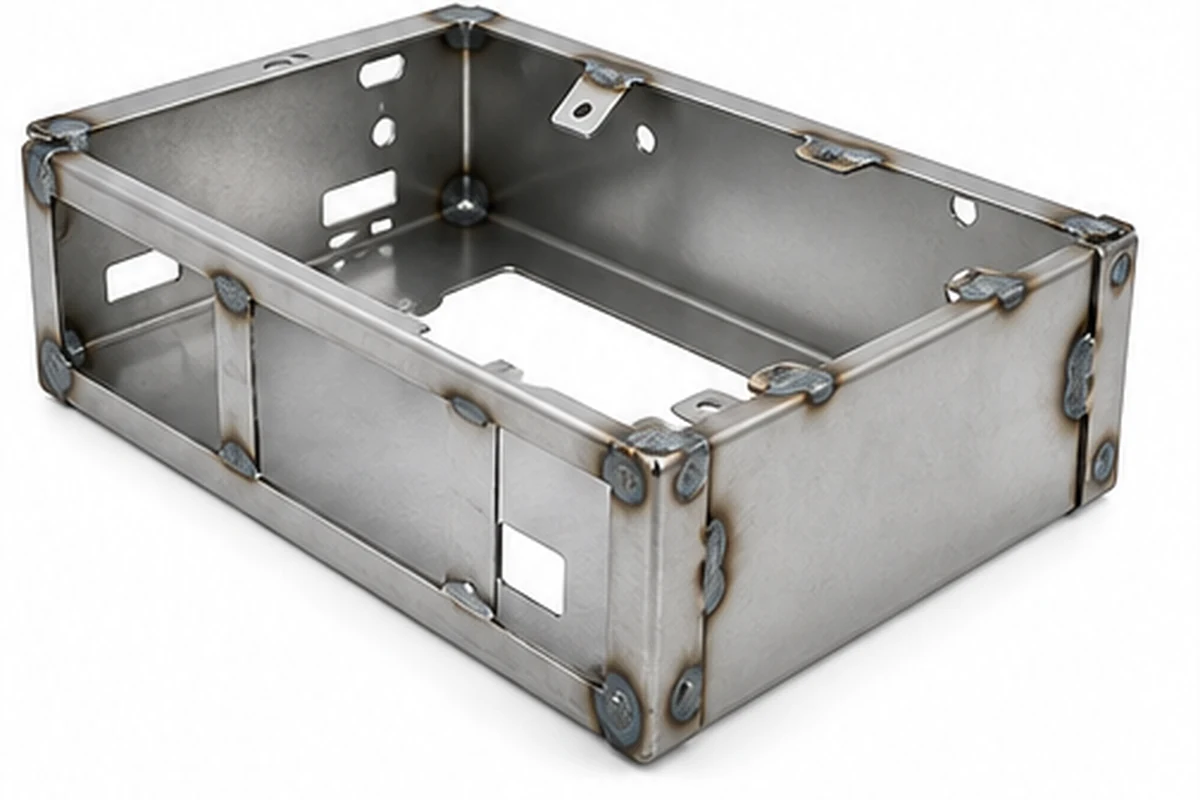
Some enclosure parts need welding. Welded corners, reinforcement brackets, tabs and frames can add strength where bending alone is not enough. But welding adds heat, and heat can move metal. A design that does not consider weld access, fixture control and distortion can create shape problems after the part leaves the welding station.
DFM should check whether the weld joint is accessible, whether the part needs a fixture, whether the weld sequence could distort the shell, whether grinding is required, and whether the welded area affects a visible surface or a later coating requirement. Welds should strengthen the part, not create a geometry negotiation.
MSTFAB reviews welded sheet metal enclosure frames and bracket structures for practical production. We focus on semi-finished metal shells and structures, not internal device building. That clarity keeps the RFQ scope clean for overseas buyers.
Surface Finish DFM: Powder Coating, Bare Metal and Visible Faces
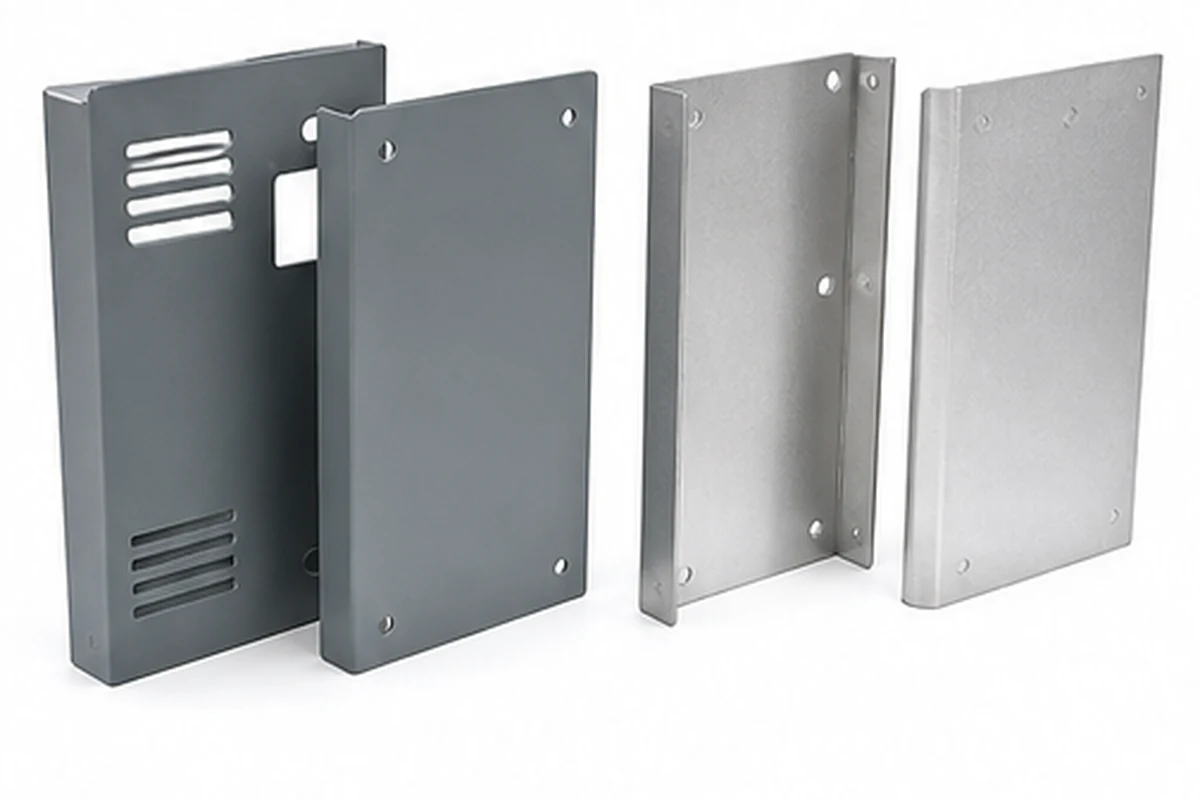
Surface finish is part of DFM because finish changes both appearance and fit. Powder coating adds thickness. Stainless steel can scratch. Aluminum may need extra surface protection. Bare steel may need corrosion planning. If the drawing only says “finish: black” and the buyer expects a premium visible surface, there is room for misunderstanding.
For enclosure panels and covers, buyers should mark visible faces, coating color, texture, gloss, corrosion requirements and areas that must stay clear. If holes, slots or threaded inserts need masking or post-finish checks, state that clearly. If several parts must match in color, samples or color references help.
MSTFAB reviews finish requirements together with fabrication steps. A nice formed panel can still fail buyer expectations if the finish note is unclear or the packing method damages the visible face. DFM connects design, process and delivery condition.
Material DFM: SPCC, Galvanized Steel, Stainless Steel and Aluminum
Material choice affects laser cutting, bending, welding, powder coating, corrosion resistance, weight and cost. SPCC or cold-rolled steel is common for powder-coated indoor enclosure panels and covers. Galvanized steel is often used when corrosion resistance matters. Stainless steel supports harsh or premium applications. Aluminum can reduce weight but needs careful bend radius and surface handling.
There is no perfect material that is cheap, feather-light, corrosion-proof, scratch-proof, easy to weld, easy to bend and beautiful forever. If such a material appears, procurement managers will probably frame the quote and hang it in the lobby. Until then, DFM helps choose the material that fits the real enclosure requirement.
Buyers should provide material grade, thickness, finish, environment and any special corrosion or appearance requirement. MSTFAB checks whether the selected material works with the required fabrication route and whether any risks should be discussed before production.
| Material | Common enclosure use | DFM concern | Buyer note to send |
|---|---|---|---|
| SPCC / cold-rolled steel | Powder-coated covers, panels, brackets and chassis trays | Coating quality, bend radius, rust protection before finish | Color, texture, visible face and thickness |
| Galvanized steel | Utility panels, outdoor-oriented brackets and back plates | Cut-edge corrosion, welding compatibility, finish adhesion | Environment and finish requirement |
| Stainless steel | Visible covers, corrosion-resistant panels and premium parts | Grain direction, scratches, burrs and forming marks | Grade, visible side and surface standard |
| Aluminum sheet | Lightweight covers, telecom cabinet panels and chassis trays | Cracking risk, denting, surface protection and finish | Alloy, temper, bend radius and packing |
Tolerance DFM: Tight Where It Matters, Practical Everywhere Else
Over-tolerancing is a quiet budget leak. If every dimension is marked tight, the factory must treat everything as critical, even features that only need clearance. This increases inspection time, scrap risk and price. Good DFM separates critical-to-fit dimensions from general dimensions.
For sheet metal enclosures, critical dimensions often include hole patterns, latch locations, hinge points, rail spacing, gasket edges, front panel cutouts and overall mounting interfaces. Less critical dimensions may allow standard sheet metal tolerances. The buyer should identify what controls fit, function and appearance.
MSTFAB encourages practical tolerance communication. If a dimension must be tight, mark it clearly and explain the interface. If a feature is non-critical, avoid unnecessary precision demands. The goal is not loose quality; the goal is useful precision where it protects the buyer’s project.
Export Packing Is Also a DFM Topic
Many buyers think DFM ends when the part is made. For international sourcing, packing belongs in the conversation. Thin panels can bend. Powder-coated covers can scratch. Stainless visible faces can mark. Small brackets can mix together if labels are unclear. A good part that arrives damaged is not a good sourcing result.
DFM for export projects should consider part shape, surface finish, stacking risk, carton weight, foam separation, pallet support and kit labeling. This is especially important for custom sheet metal enclosure parts with large flat faces or many similar brackets. Packing may not sound exciting, but neither does explaining freight damage to a customer.
MSTFAB can provide packing photos, label confirmation and practical export packing support for drawing-based sheet metal enclosure projects. This gives overseas buyers more confidence before shipment release.
DFM Trust Table for OEM Buyers
| Buyer risk | DFM question | Evidence to request | Result buyers want |
|---|---|---|---|
| Parts do not fit during later project integration | Which dimensions control holes, hinges, rails or mating panels? | Critical dimension check photos or measurement report | Repeatable fit without field modification |
| Prototype works, batch changes unexpectedly | Is the drawing revision, material and process route locked? | Approved revision number and first-piece confirmation | Stable repeat production |
| Visible panels arrive scratched | Which faces are visible and how are they protected? | Finish photos and packing photos | Clean surface condition on arrival |
| Powder coating affects hardware or holes | Which holes, threads or contact areas need protection? | Masking notes and post-finish inspection | Hardware and cutouts still fit after finish |
| Quote misses key work | Does the quote include cutting, bending, welding, finish, QC and packing? | Process list and scope confirmation | Fewer cost surprises after PO |
How MSTFAB Handles DFM for Sheet Metal Fabrication
MSTFAB supports overseas OEM buyers with drawing-based sheet metal fabrication for custom enclosure shells, panels, covers, brackets and semi-finished metal structures. A typical project starts with RFQ file review, then DFM feedback, material confirmation, laser cutting, CNC bending, welding or hardware preparation where needed, surface finish, inspection and export packing.
The review is practical. We check whether the design can be manufactured with stable quality, not whether it sounds impressive in a brochure. If a bend is risky, we flag it. If a hole may distort, we point it out. If a surface finish note is unclear, we ask. If the packing requirement is missing for visible panels, we recommend defining it. This helps buyers reduce rework, avoid schedule delays and compare quotes more fairly.
This page also supports commercial search intent for buyers looking for DFM for sheet metal fabrication, sheet metal enclosure DFM, custom sheet metal fabrication DFM, laser cutting and bending DFM review, sheet metal design for manufacturability, OEM sheet metal enclosure supplier and China sheet metal fabrication factory. The wording stays focused on MSTFAB’s real work: custom metal enclosure parts and related fabricated sheet metal structures.
DFM Checklist Before You Send a Purchase Order
Before releasing an order, use this quick checklist. It is not glamorous, but neither is emergency rework. Good sourcing is often boring in the best possible way.
Drawing checklist
- STEP or STP file included
- 2D drawing includes revision
- DXF flat file checked
- Critical dimensions marked
Process checklist
- Laser cutouts reviewed
- Bends and flange lengths checked
- Weld access confirmed
- PEM hardware positions defined
Delivery checklist
- Surface finish specified
- Visible faces protected
- Inspection evidence agreed
- Export packing confirmed
Related MSTFAB Resources
For broader capability, visit Custom Sheet Metal Fabrication. For enclosure-specific projects, see Custom Sheet Metal Enclosure Fabrication. For process pages, review Laser Cutting Services, Sheet Metal Bending Services, Welding Services and Surface Treatment.
For procurement preparation, read What Files Are Needed for a Sheet Metal Fabrication Quote?, Sheet Metal RFQ Drawing Checklist, Sheet Metal Fabrication Cost for Enclosures and 7 DFM Rules for Sheet Metal Fabrication. If drawings are ready, use the Online Laser Cutting Quotation Service.
FAQ: DFM for Sheet Metal Fabrication
What does DFM mean in sheet metal fabrication?
DFM means design for manufacturing. It checks whether a sheet metal part can be laser cut, bent, welded, finished, inspected and packed according to the buyer’s drawing without avoidable production risk.
Why is DFM important for custom sheet metal enclosures?
Custom enclosures depend on holes, bends, cutouts, brackets, finish and fit. DFM helps prevent distorted holes, cracked bends, poor hardware positions, coating issues and shipping damage before production starts.
What files are needed for a DFM review?
Send STEP or STP models, 2D PDF or DWG drawings, DXF flat files if available, material grade, thickness, finish, quantity, tolerance notes, hardware requirements and visible surface notes.
Can MSTFAB review DFM before quoting?
Yes. MSTFAB can review manufacturability risks for custom sheet metal enclosure shells, panels, brackets, covers, louver plates and chassis trays before confirming quotation and production route.
Does DFM reduce sheet metal fabrication cost?
DFM can reduce unnecessary cost by simplifying bends, improving hole placement, avoiding over-tight tolerances, clarifying finish requirements and preventing rework. It does not make metal free, but it does help stop the expensive surprises from sneaking in.
Is MSTFAB making the full final device?
No. MSTFAB focuses on semi-finished custom sheet metal enclosure parts and related fabricated metal structures from buyer drawings. The buyer controls later project integration.
Need a DFM review before ordering sheet metal enclosure parts?
Send your STEP, DXF, DWG or PDF drawings with material, quantity, finish and packing notes. MSTFAB will review the sheet metal fabrication risks before quotation.
 WeChat Contact
 WhatsApp Me Directly