Use this page for the two DFM mistakes that cause the most rework
This page narrows DFM down to bend radius and hole placement, because those two tiny drawing decisions can wreck a batch with impressive efficiency. CAD is calm; cracked metal is not.
This page has been separated from the broader DFM design rules article so Google and buyers can see the job of this article clearly. The useful question here is not “can someone make metal parts?” It is: what should a buyer check before sending drawings, approving a quote or moving into production?
- Keep inside bend radius at least equal to material thickness unless the factory confirms tooling.
- Keep holes away from bend lines so they do not stretch into odd shapes.
- Add reliefs at corners where material needs space to move.
- Review flange height against press brake tooling access.
- Ask for DFM feedback before prototype cutting, not after first article failure.
| 1 | Keep inside bend radius at least equal to material thickness unless the factory confirms tooling. |
| 2 | Keep holes away from bend lines so they do not stretch into odd shapes. |
| 3 | Add reliefs at corners where material needs space to move. |
| 4 | Review flange height against press brake tooling access. |
| 5 | Ask for DFM feedback before prototype cutting, not after first article failure. |
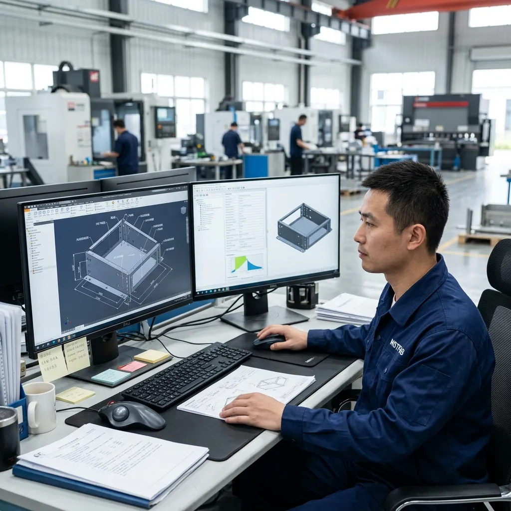
Let’s be brutally honest: your 3D CAD software will let you draw absolutely anything. It doesn’t care if a flange is physically impossible to bend, or if a hole is so close to the edge that the metal will rip in half. But the CNC press brake on the factory floor? It cares a lot.
Every week, OEM engineers send us brilliant designs that are completely unmanufacturable without expensive manual rework. When you ignore basic Design for Manufacturability (DFM) rules, you end up paying for scrapped parts, delayed shipments, and massive headaches during final assembly. At MSTFab, we don’t just blindly cut and bend what you send us. We engineer it for reality.
The 7 Sheet Metal DFM Rules You Can’t Ignore
1. The “Impossible Bend Radius” Rule
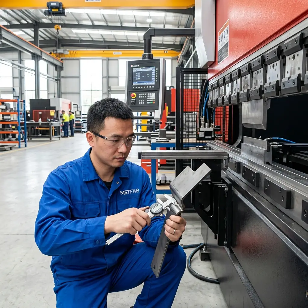
If you specify a 0.5mm inside bend radius on a 3mm thick aluminum bracket, physics is going to laugh at you. The metal will aggressively stretch on the outside and crack wide open before the machine even finishes the stroke.
The Fix: Always use an inside bend radius that is at least equal to the material thickness (1 x T) for mild steel. For aluminum (like 6061), you need at least 2 x T to avoid fracturing. Standardizing your radii also means the operator doesn’t have to change the press brake tooling 5 times for a single part.
2. The “Deformed Hole” Rule (Hole-to-Bend Distance)
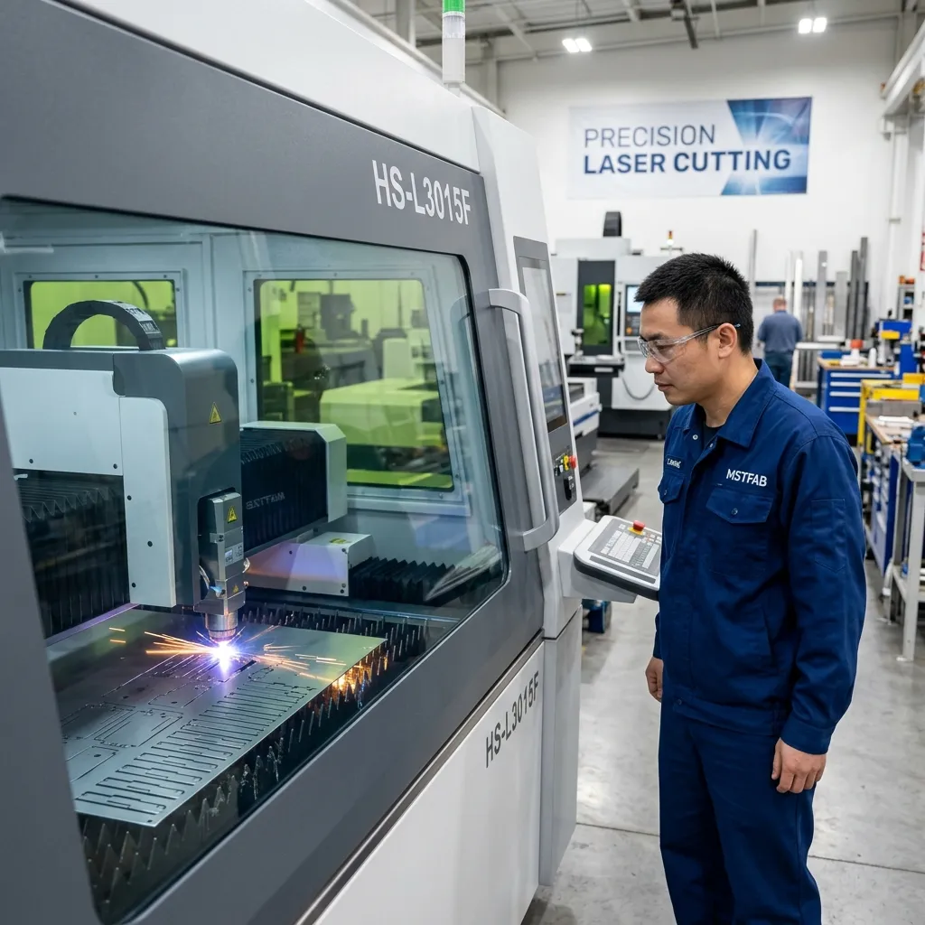
You place a perfectly round mounting hole right next to the bend line in SolidWorks. In real life, when the CNC press brake folds that edge, the metal pulls and stretches. Your perfect circle is now an ugly oval, and your M4 screw isn’t going in.
The Fix: Keep all holes, slots, and cutouts away from the bend line by a distance of at least 2.5 x Material Thickness + Bend Radius. If you absolutely must have a hole close to the bend, we’ll have to laser cut it after bending, which drastically increases your unit cost.
3. The “Chewed Corner” Rule (Missing Bend Reliefs)
Metal does not like to tear itself apart gracefully. If you try to bend a flange that doesn’t extend the full width of the part without providing a relief cut, the corners will buckle, bulge, and look like a dog chewed on them.
The Fix: Always add bend reliefs adjacent to the bend. The relief cutout should be at least as wide as the material thickness, and extend deeper than the bend radius. This allows the flange to fold cleanly without ripping the surrounding flat sheet.
4. The “Magic Wand Welding” Rule
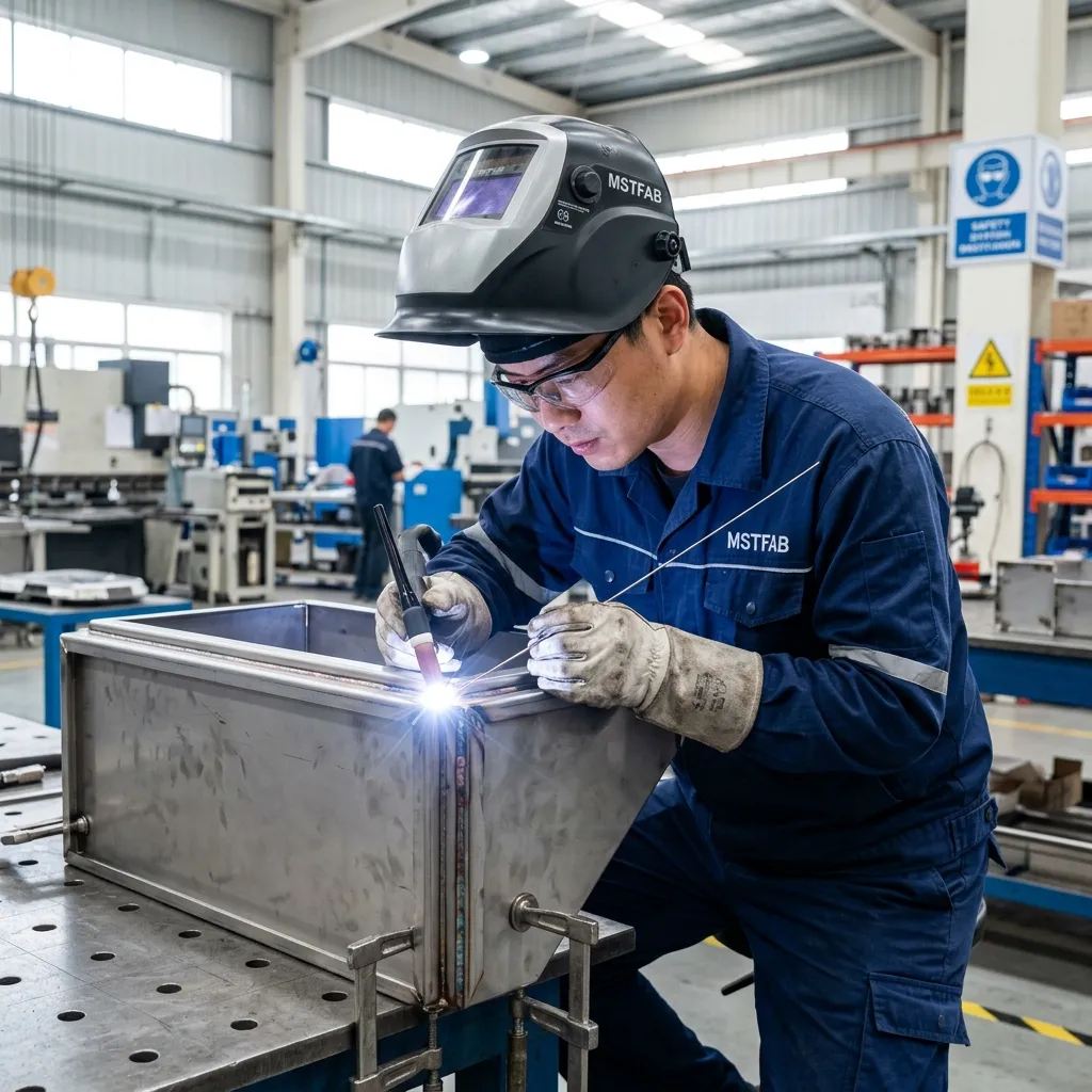
Our welders are phenomenal, but their TIG torches aren’t made of magic dust. If you design a fully enclosed box with a seam located deep inside a 20mm gap, there is physically no way to get a welding torch (or a grinding wheel) in there to finish the joint.
The Fix: Design your welded joints on the outside corners whenever possible. Give the welding nozzle room to breathe. If you’re designing for integrated fabrication and welding, ensure the torch angle is accessible.
5. The “Hardware Too Close” Rule
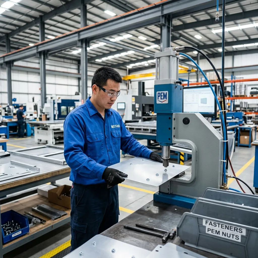
Self-clinching fasteners (like PEM nuts or studs) need solid metal around them to grip onto. If you place a PEM nut too close to the edge of the part, the pressure from the insertion press will bulge the edge outward, ruining your dimensional tolerances.
The Fix: Follow the manufacturer’s spec for edge distance (usually at least 1.5 times the hole diameter).
6. The “Machining Tolerance Fantasy”
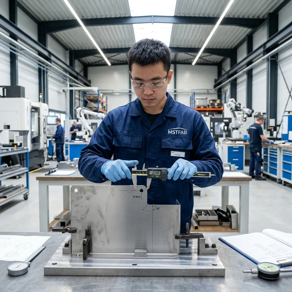
We see drawings every day specifying ±0.01mm (±0.0004″) on a bent sheet metal bracket. Sheet metal breathes. It springs back. It varies in thickness across the raw coil. If you demand CNC machining tolerances on folded sheet metal, we have to quote you CNC machining prices.
The Fix: Design your assemblies to accept standard sheet metal tolerances: ±0.1mm for laser cutting, and ±0.2mm for bending. Use slotted holes for mounting instead of perfectly round ones to allow for assembly play.
7. The “Powder Coated Threads” Disaster
You designed the perfect part, we cut it, bent it, and installed the threaded inserts. Then it goes to surface finishing. If the drawing doesn’t explicitly call out masking, the powder coating process will bake solid plastic right into your M4 threads. Your assembly team will spend hours manually re-tapping every single hole.
The Fix: Clearly define on your PDF which areas, holes, or studs must remain completely free of paint. We will plug them with high-temp silicone before coating.
The MSTFab Engineering Reality Check
How do you know if your current supplier is actually reviewing your parts, or just hitting “Print” and hoping for the best? Use this vendor checklist.
| Engineering Protocol | The “Blind-Cut” Factory | The MSTFab OEM Standard |
|---|---|---|
| DFM Review | Assumes the CAD file is flawless. Cuts it. Fails to bend it. Blames you. | Performs a complete pre-production audit for prototypes and low volume runs. |
| Flat Pattern Calculation | Uses default software K-factors, resulting in short flanges. | Calculates exact Bend Deductions based on the physical tooling in our factory. |
| Finishing Control | Powder coats everything blindly. Threads get destroyed. | Strict masking protocols based on drawing callouts. Clean threads every time. |
Ready for a Manufacturer That Actually Engineers?
Stop wasting money trying to manufacture unmanufacturable parts. Whether you are dealing with a quick small batch metal fabrication run or setting up a major OEM supply chain, having a partner who speaks the brutal truth about DFM will save you thousands of dollars.
Send us your DXF, STEP, and PDF drawings. We’ll tell you exactly what works, what doesn’t, and how to fix it before a single piece of metal is cut.
Upload CAD Files for DFM Review
Or visit our CAD File Upload Center directly.
 WeChat Contact
 WhatsApp Me Directly