
DFM stands for Design for Manufacturability, which is a fancy way of saying “design the part so the factory does not hate you.” Most expensive sheet metal problems are not born on the shop floor. They are born in CAD, usually around 11pm, when someone clicked “default” on every dimension and called it engineering bravery.
Quick answer: Follow these sheet metal DFM basics: keep bend radius at least equal to the material thickness, keep holes and cutouts at least 2x thickness from a free edge and about 3x thickness from a bend line, avoid sharp internal corners by adding reliefs, design welds that will not distort the panel, and specify standard hardware. Each rule removes a setup snag, scrap risk, or rework loop. The goal is not a prettier drawing. It is a part that comes out right the first time, which is the cheapest part there is.

Why DFM Pays You Back Before Production
A drawing mistake is cheap to fix in CAD and brutal to fix after parts are cut, bent, coated, packed, and shipped across an ocean. A bend that cracks, a hole that lands on the bend line, a weld that pulls a panel out of square: every one of these is free to prevent and expensive to discover.
A supplier that reviews your design before quoting is handing you free money. Ignoring that feedback is the most expensive humility lesson in the building. DFM is the difference between “first article passed” and “we rebuilt the tooling.”
Rule 1: Bend Radius Is Not a Wish
The inside bend radius should usually be at least the material thickness. For a 2 mm sheet, start with a 2 mm inside radius unless the supplier confirms a different tool and material combination. Asking thick material to fold around a tiny radius is how you get cracks, springback drama, and a press brake operator quietly judging your life choices.
Good RFQs name the material grade, thickness, and expected bend radius. Better RFQs ask the shop to confirm the closest standard tooling before production.

Rule 2: Keep Holes Away From Edges and Bends
For free edges, keep holes and cutouts at least 2x material thickness away from the edge. For bend lines, keep them around 3x material thickness away, unless the supplier approves the geometry. Holes too close to bends can stretch, oval, or relocate during forming. This is not a quality issue. It is physics wearing safety shoes.
A hole on the bend line is the classic “small drawing detail, large remake invoice” problem. Move it, slot it, add a relief, or ask the supplier for the least painful option before release.

Rule 3: Sharp Internal Corners Need Relief
Sharp internal corners create stress points, slow cutting, and increase crack risk during forming. Add small radii, corner reliefs, or slot-end reliefs where cuts meet bends or where the material needs room to move. It is a few seconds in CAD and a very nice way to avoid scrap.
If your bracket has a perfect knife-sharp inside corner, the metal will eventually vote on that decision. Metal is not sentimental.
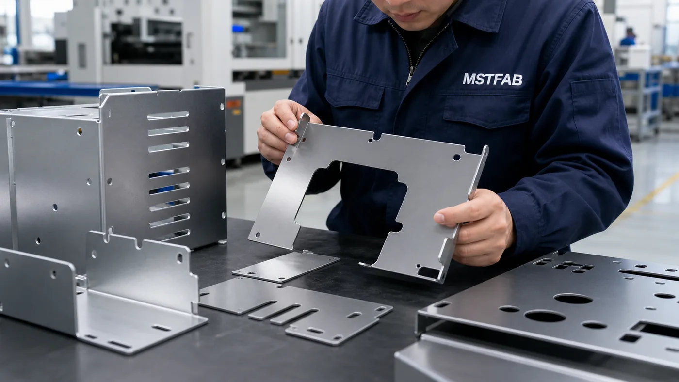
Rule 4: Weld Smart, or Weld Warped
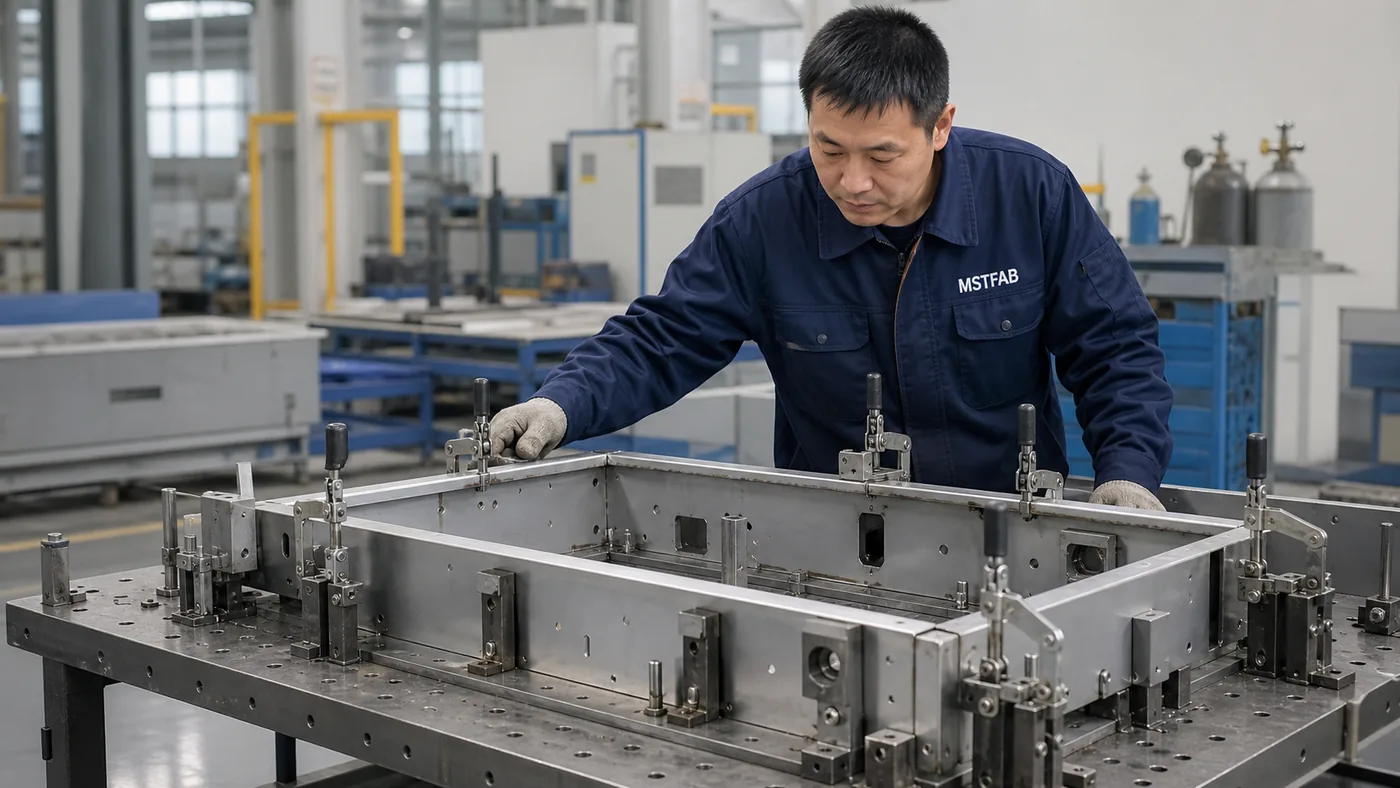
Welds shrink as they cool. Thin sheet metal panels can warp like a bad excuse in direct sunlight. Design welds with distortion in mind: use intermittent welds where strength allows, keep welds symmetric, add fixtures for repeatable assemblies, and avoid welding thin gauge to heavy stock without a plan.
A warped enclosure is rarely “just a welding problem.” Most of the time, the drawing invited the problem in, gave it a chair, and offered coffee.
Rule 5: Standardize Hardware
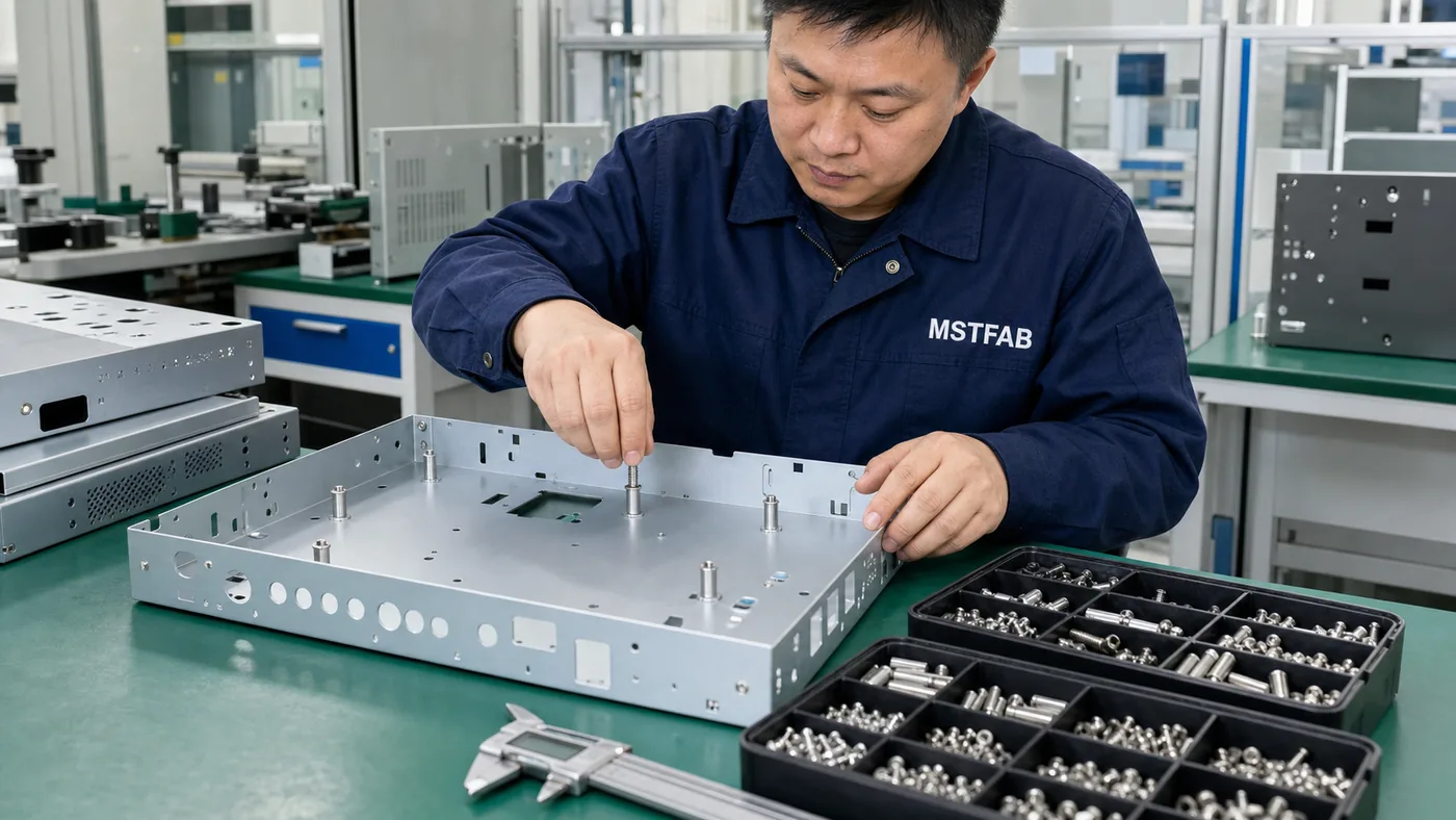
Use standard PEM inserts, standoffs, screws, and threads that the factory can source quickly. Oddball hardware may look harmless on the drawing, but it adds purchasing delays, MOQ surprises, and awkward assembly conversations nobody asked for.
Standard hardware is not boring. It is available, proven, and cheap. Custom hardware is a tiny adventure with a purchase order attached.
Rule 6: Keep Parts Flat-ish and Nestable
The more a part folds into a little metal puzzle, the harder it is to fixture, weld, finish, and inspect. Design for reasonable flatness where possible, and remember that parts that nest efficiently on a sheet waste less material. That directly affects price, as covered in Sheet Metal Fabrication Cost: What Actually Drives Your Part Price.
When two designs function the same, the version that nests better and needs fewer operations usually wins. Quietly. On the quote.
Rule 7: Tolerances by Function, Not Fear
Tighten only what must fit, seal, align, or move. Loosen cosmetic edges, non-critical brackets, and clearance features. A +/-0.05 mm tolerance on a hidden edge is you paying for precision nobody invited to the party.
For a practical tolerance breakdown, use Sheet Metal Tolerances Explained for OEM Buyers. The short version: tight tolerances cost more because they add setup time, inspection time, and scrap risk.
DFM Trust Table for OEM Buyers
A useful DFM review does not just say “looks fine.” It should point to specific features, explain the risk, and suggest a cleaner manufacturing path. Use this table when you want to separate a real engineering supplier from someone who is just very fast with a quote.
| DFM Area | What a Good Supplier Checks | Buyer Trust Signal | Risk If Ignored |
|---|---|---|---|
| Bend radius | Material thickness, bend direction, tooling radius, springback | They confirm tool availability before quoting production volume | Cracks, wrong angles, slow setup, remakes |
| Hole placement | Hole-to-edge distance and hole-to-bend-line distance | They flag holes that may distort during forming | Oval holes, assembly mismatch, rejected first article |
| Corner relief | Internal corners, slot ends, bend relief, stress points | They recommend reliefs instead of silently cutting risky geometry | Cracking, tearing, burrs, slow laser/punch time |
| Welding plan | Fixture strategy, weld length, sequence, symmetry | They talk about distortion before production, not after complaints | Warped panels, poor fit, rework loops |
| Hardware | PEM sizes, thread standards, insert clearance, sourcing availability | They suggest stocked hardware where possible | Lead-time delay, special MOQ, assembly surprises |
| Finish compatibility | Masking, coating thickness, grounding pads, material fit | They connect the drawing to the finishing process | Threads filled with powder, bad grounding, finish defects |
The DFM Checklist
- Bend radius is at least material thickness unless the supplier approves the tooling.
- Holes are at least 2x thickness from free edges and about 3x thickness from bend lines.
- Internal corners are relieved; no sharp stress points where material needs to move.
- Welds are symmetric or intermittent where the strength requirement allows it.
- Hardware is standardized: PEM inserts, common threads, common fasteners.
- Tolerances are tight only where function demands it.
- Flatness, nesting, material usage, and finish are considered before release.
Finish and Material Still Matter
DFM does not end at cutting and bending. Powder coating adds thickness. Anodizing only works on aluminum. Plating behaves differently from a cosmetic finish. If a thread, grounding pad, gasket face, or sliding feature needs to survive finishing, mark it clearly.
For the finish side of the problem, see Powder Coating vs Anodizing vs Plating: Sheet Metal Finishes Guide. A finish chosen after the drawing is done can turn a simple part into a small manufacturing puzzle.
The Expensive Mistakes DFM Prevents
- A hole on the bend line: remake.
- A bend radius smaller than the material can tolerate: cracks and scrap.
- A sharp internal corner: stress crack plus slower cutting.
- A continuous weld on thin sheet: warped panel, angry assembly team.
- Custom hardware where standard would work: special order, wait time, cost.
- Over-tight tolerances: more inspection, more rejects, more calendar.
How to Get DFM Feedback Without Begging
Send the drawing early, with material, finish, quantity, and critical dimensions noted. Then ask one direct question: “Where will this be hard or expensive to make?” A good supplier answers with specific risks and practical alternatives.
If a supplier quotes a complex bent or welded part with zero DFM comments, that is not confidence. It may be a later surprise wearing a clean shirt. The feedback is free. The rework is not.
Red Flags in a Design Review
- The supplier quotes with no DFM questions at all.
- Every dimension uses default tight tolerances “just to be safe.”
- Holes sit on or near bend lines.
- Welds are continuous on thin gauge without a distortion plan.
- Custom hardware appears where standard hardware would work.
- There are no reliefs at internal corners or slot ends.
Key Takeaways
- DFM means designing the part so the factory can make it right the first time.
- Fixes are cheap in CAD and expensive after production starts.
- Radius, hole placement, reliefs, welding, hardware, and tolerance control are the big levers.
- A supplier’s DFM feedback is a trust signal, not a nuisance.
- The best part is not the fanciest drawing. It is the one that works, ships, and does not come back for revenge.
Frequently Asked Questions
What does DFM mean in sheet metal?
DFM means Design for Manufacturability: designing the part so it is practical, repeatable, and cost-efficient to make. In sheet metal, that usually means checking bend radius, hole placement, corner reliefs, welding strategy, standard hardware, and realistic tolerances before production.
How far should a hole be from a bend?
As a practical starting point, keep holes about 2-3x the material thickness away from a bend line, and at least 2x thickness from a free edge. The exact distance depends on the material, thickness, tooling, and whether the hole can be slotted or moved.
Why can’t I use a tight bend radius?
A bend radius smaller than the material can tolerate may crack the sheet during forming. A good rule of thumb is to keep the inside radius at least equal to the material thickness, then confirm the shop’s available tooling before release.
How does DFM lower my cost?
DFM removes setup snags, scrap risk, rework loops, and special-order surprises. A part that passes first article inspection without remakes is usually cheaper than a part that looked perfect in CAD but fought the factory all week.
Should my supplier review my design?
Yes. Ask for DFM feedback before production. Specific comments on bend radius, hole placement, welding, finish, and hardware are signs of an engineering partner. Silence is not always confidence; sometimes it is just delayed bad news.
Need a DFM Check Before You Cut Metal?
Send MSTFAB your drawing, material, finish, tolerance requirements, and target quantity. We can review the risky features before they become rework, scrap, or the kind of calendar surprise nobody wants to explain on a Monday call.
 WeChat Contact
 WhatsApp Me Directly