Sheet Metal Enclosure Manufacturer for Electronics Startups
How to source a custom metal enclosure that supports PCB fit, connector alignment, grounding, shielding strategy, thermal features, sealing and repeat production—without asking the fabricator to make certification promises it cannot control.
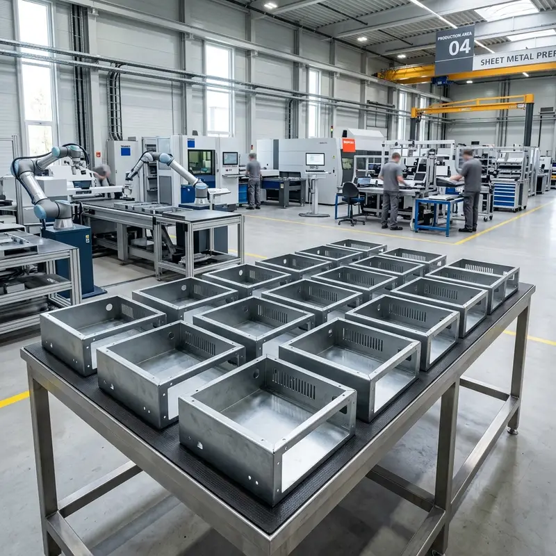
A sheet metal enclosure manufacturer for electronics startups should understand more than the outside shape. The supplier must translate controlled drawings into accurate panels, bent chassis parts, PCB mounts, hardware, welded features, finish and inspection records. It should also preserve bonding areas, gasket lands and airflow features specified by your electrical, thermal and compliance engineers. The fabricator supports certification-ready construction; qualified engineers and laboratories determine whether the complete product actually passes FCC, CE, UL or ingress testing.
For an electronics startup, the enclosure is simultaneously a mechanical structure, an assembly interface and part of the product’s electrical and thermal architecture. A connector opening that shifts after bending can prevent a cable from seating. Powder coat on a bonding point can interrupt chassis continuity. A vent pattern can improve airflow yet create an EMI or ingress problem if it is not reviewed as part of the full system.
This is therefore a commercial sourcing decision, not only a sheet metal price comparison. The right manufacturing partner asks for the PCB, connector and assembly context, identifies fabrication risks before cutting, and builds a controlled path from prototype to pilot production. For the broader supplier-selection framework, start with the best sheet metal fabrication manufacturer for startups guide.
What an electronics enclosure manufacturer actually controls
Laser-cut openings, bend sequence, flange geometry, welded joints and removable panels.
Standoffs, PEM fasteners, brackets, card guides, rails and service clearances.
Masked areas, studs, washers and contact lands specified for chassis continuity.
Vents, fan openings, mounting areas and brackets designed by the product team.
Coating, masking, gasket lands, fastener spacing, cable entries and packing.
Revision control, first-article inspection and pilot-batch fit checks.
Responsibility boundary: the enclosure manufacturer fabricates the specified metal features and can flag obvious DFM conflicts. EMI behavior, thermal performance, electrical safety and regulatory compliance depend on the complete product. Final requirements and acceptance tests should be owned by the startup’s qualified engineering team and accredited laboratories.
The enclosure specification that should accompany your RFQ
Do not send only a visual render. A manufacturing-ready RFQ should include a STEP model and a controlled 2D drawing, plus the data that connects the enclosure to the electronics inside it.
- PCB outline, mount points and maximum component heights
- Connector models, mating clearance and controlled cutout dimensions
- Material grade, thickness and surface finish
- Critical dimensions, datums and tolerance requirements
- Bonding studs, bare-metal lands and masked areas
- Vent, fan, filter and thermal-interface locations
- Gasket, cable gland and environmental-sealing requirements
- Prototype, pilot and forecast quantities
- Target product standards and laboratory test plan
- Inspection records, packaging and destination requirements
Use the sheet metal DFM handbook to review general fabrication constraints before quotation. The manufacturer still needs the actual connector drawings, PCB stack-up and product requirements to evaluate the enclosure.
Seven technical areas to review with an enclosure fabricator
1. Seam design, shielding interfaces and finish masking
Metal can support an EMI shielding strategy only when the complete construction provides the required conductive path. Enclosure factors may include overlapping flanges, controlled seam gaps, fastener spacing, conductive gaskets or spring fingers, bonding hardware and uncoated contact lands. Powder coating is electrically insulating, so the drawing must identify areas that remain bare or use an approved bonding method.
The fabricator should confirm whether masking is practical and repeatable. It should not promise that a visually closed box will pass emissions testing. Pre-compliance testing on the assembled product is the appropriate way to evaluate the shielding strategy.
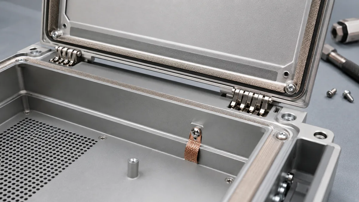
2. Grounding and bonding points
A grounding stud, serrated washer or bonding strap only works when the surrounding construction is defined correctly. Specify the stud type and location, hardware stack, masked area, coating boundary and inspection method. If continuity resistance is a critical requirement, put the test method and acceptance limit on the quality plan rather than relying on a generic “grounded enclosure” note.
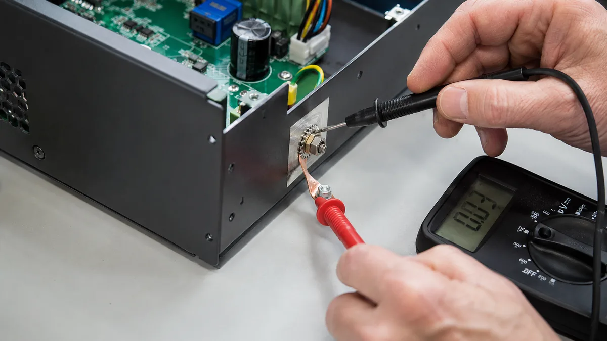
3. Thermal features that remain manufacturable
The product’s thermal engineer should define heat loads and the cooling concept. The sheet metal supplier then reviews whether fan cutouts, perforations, louvers, brackets and flat thermal-interface areas can be produced without weakening a panel or interfering with bends and hardware.
A fabricated enclosure is not automatically a heat sink. Extruded fins, machined cold plates and heat pipes may require separate components or suppliers. What the enclosure manufacturer can control is the geometry, flatness and assembly interface specified for those thermal components.
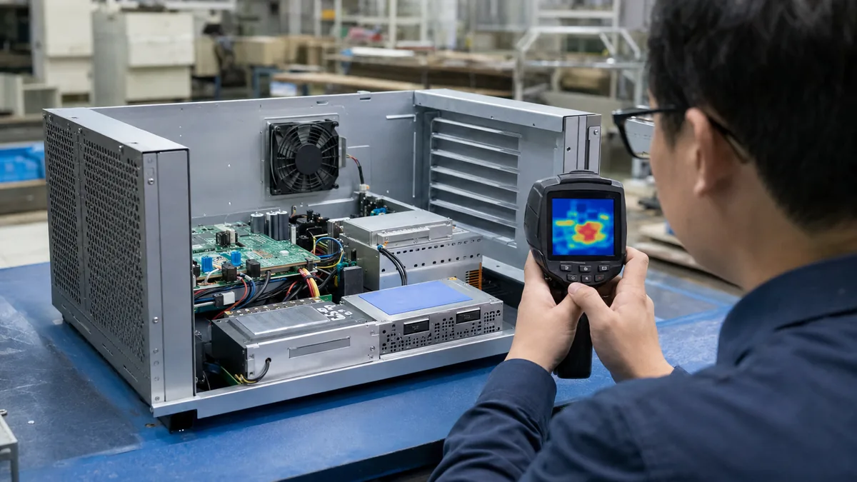
4. Precision connector panels
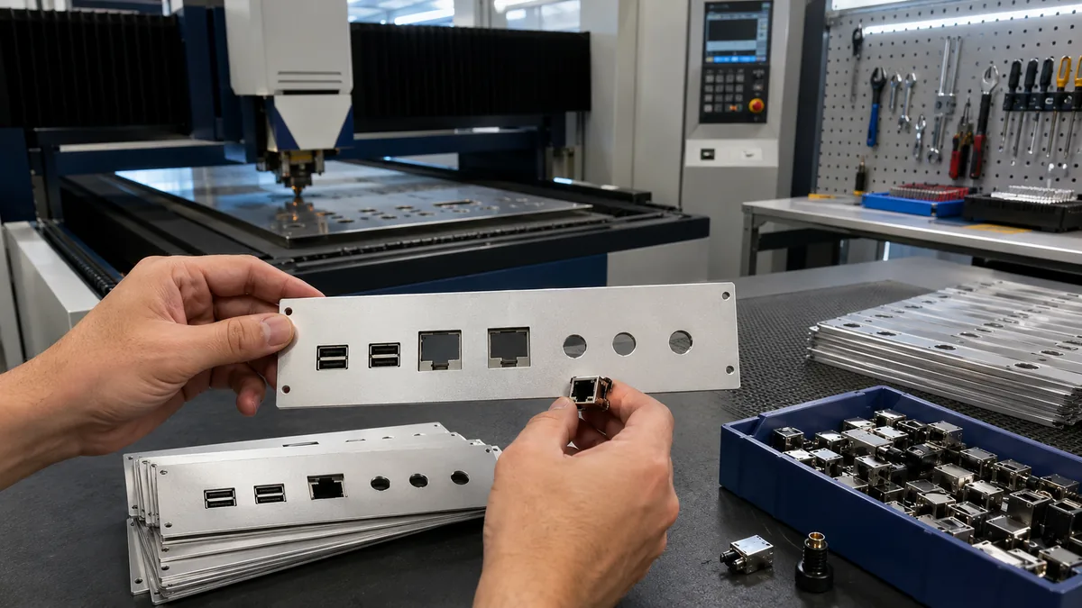
Connector alignment depends on more than the nominal laser-cut hole. The tolerance stack can include PCB location, standoff position, panel bend, coating buildup, connector float and mating-cable clearance. Use the connector manufacturer’s recommended panel cutout and establish functional datums from the PCB or chassis interface.
Do not publish a universal ±0.1 or ±0.2 mm tolerance for all connector openings. Required tolerance depends on panel thickness, feature geometry, bend relationship, finishing and process capability. Ask the supplier to confirm the controlled dimensions before production. MSTFAB’s metal laser cutting services cover custom panel openings, vents and mounting features.
5. PCB mounting, internal brackets and service access
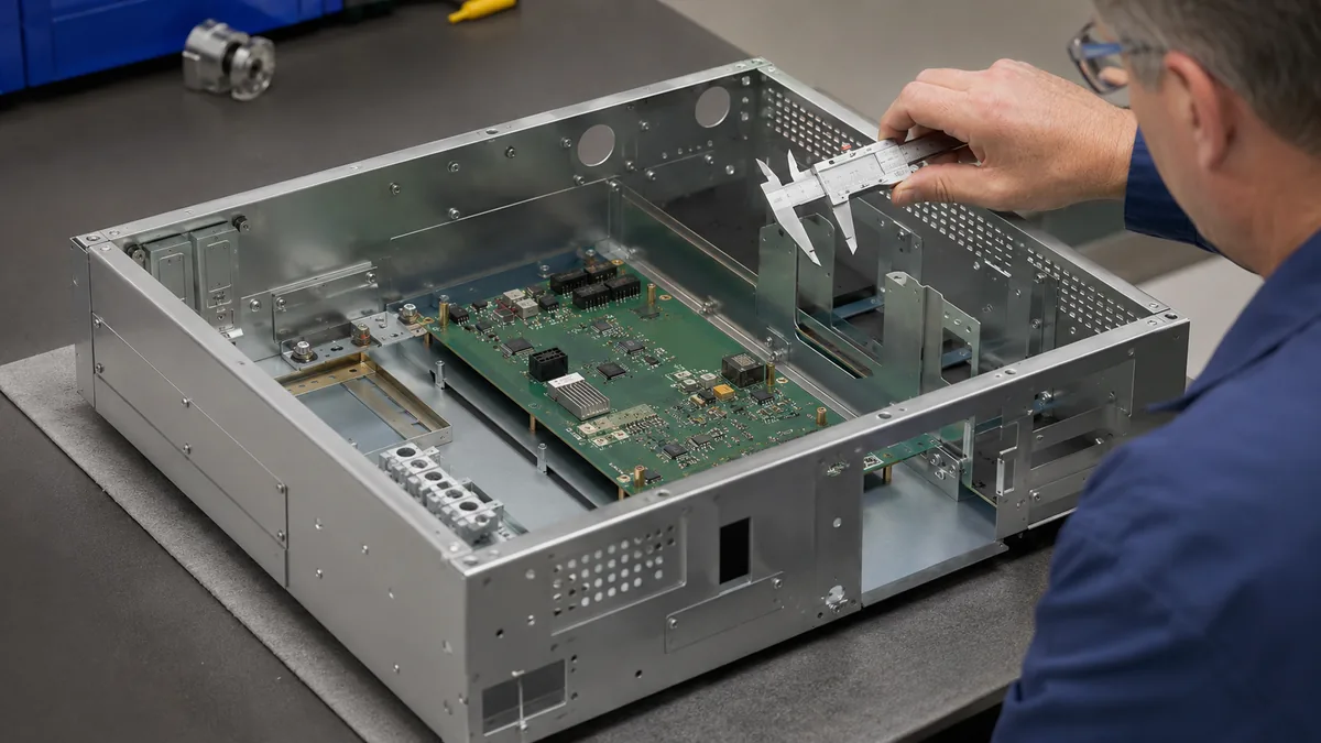
The drawing should define standoff type, height and positional tolerance; PEM hardware; card guides; DIN rails; shields; internal brackets; cable bend radius and assembly-tool access. A feature can be dimensionally correct yet impossible to assemble if a screwdriver, cable or connector has no clearance.
The supplier should review these internal structures together with the bend sequence and CNC sheet metal bending process. Internal mounting features often matter more to product function than the cosmetic outside corners.
6. Environmental sealing and ingress strategy
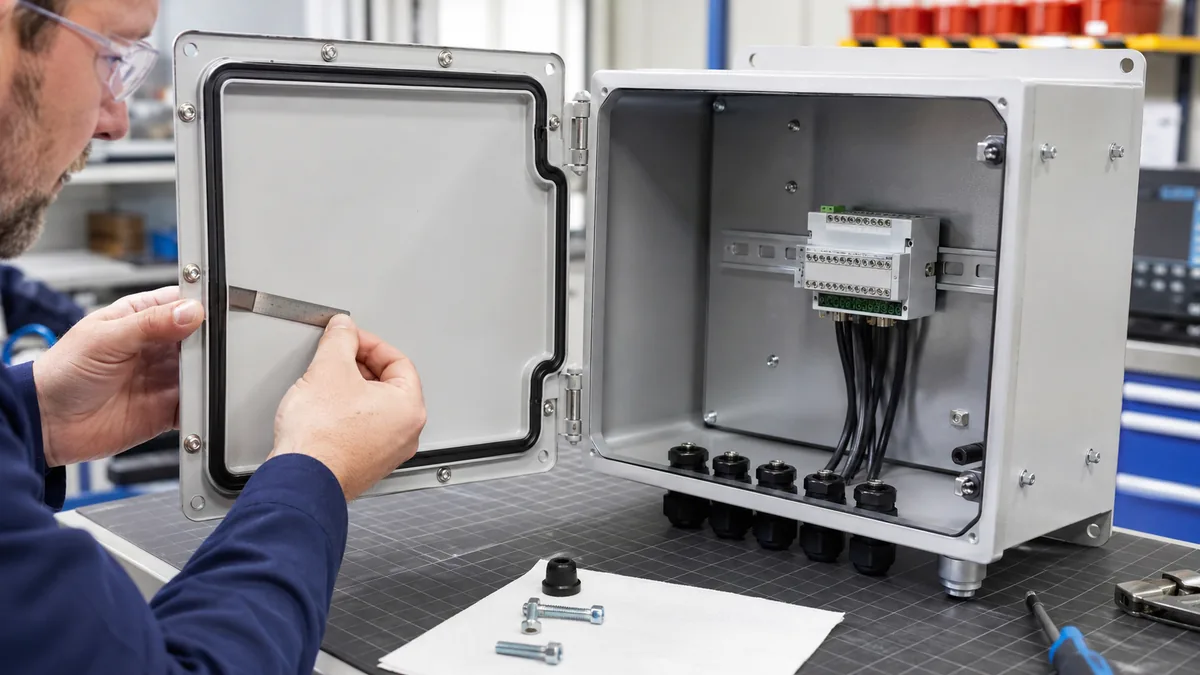
If the product has an ingress requirement, define the target test standard, environment, gasket material, compression range, seam construction, fastener spacing, cable glands and drain or pressure-equalization strategy. A fabricated enclosure should not be advertised as IP54, IP65 or another rating solely from its appearance.
The completed configuration—including doors, glands, vents, filters and assembly torque—must be tested under the applicable method. The manufacturer can build the specified gasket land and sealing structure and support prototype testing.
7. Material and finish selection
| Material route | Typical reason to consider it | Manufacturing questions |
|---|---|---|
| Cold-rolled or galvanized steel | Cost-effective stiffness and a conductive metal structure for many indoor enclosures. | Corrosion protection, coating, weight, welding and masked bonding areas. |
| Aluminum sheet | Lower weight and good corrosion behavior for portable or thermally sensitive products. | Alloy, bend radius, welding, anodizing, grounding and galvanic interfaces. |
| 304/316 stainless steel | Corrosion resistance, cleanability or demanding environments. | Grade, finish direction, weld cleanup, passivation, weight and cost. |
Finish selection should be driven by environment, appearance, bonding and assembly—not color alone. Review powder coating, anodizing, plating, passivation, masking and packing on the surface treatment services page.
Prototype and inspection plan for an electronics enclosure
Confirm PCB, connectors, displays, controls, cable entries, thermal parts and fastening access.
Check basic fit, bend geometry, internal access and assembly sequence before cosmetic decisions are frozen.
Build the real coating, masking, gasket and hardware configuration used for pre-compliance tests.
Measure controlled cutouts, PCB mounts, panel interfaces and functional datums.
Evaluate repeatability, connector fit, hardware installation, cosmetic quality and packing.
Freeze the drawing revision, process scope, approved sample and inspection plan.
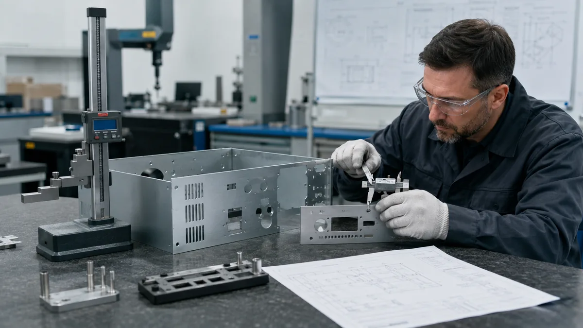
One good sample is not proof of repeat production. The article why an approved prototype does not guarantee stable mass production explains why fixtures, handling, finishing and inspection must be tested at pilot quantity.
Supplier scorecard for an electronics startup
| Score area | Strong evidence | Warning sign |
|---|---|---|
| DFM response | Written questions about bends, interfaces, masking, gasket lands and assembly access. | A complex enclosure is quoted from a render with no technical questions. |
| Process route | Clear laser cutting, bending, hardware, welding, finishing and inspection scope. | Secondary operations and subcontracted finishes are not disclosed. |
| Functional interfaces | Datums and inspection plan for connector and PCB locations. | Only overall outside dimensions are checked. |
| Compliance support | Builds controlled prototypes and records the specified construction. | Promises FCC, CE, UL or IP compliance without testing the finished product. |
| Pilot readiness | Uses revision control, FAI data and a repeatable production route. | Prototype fabrication is treated as an unrelated one-off job. |
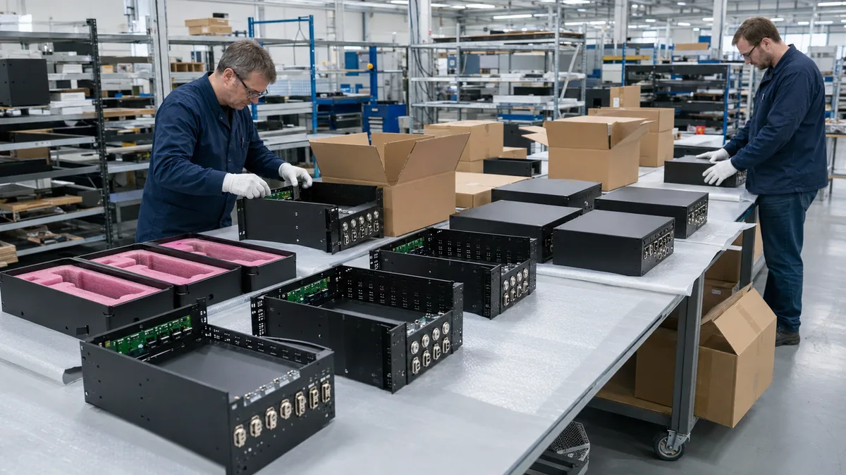
Why electronics startups may shortlist MSTFAB
MSTFAB manufactures drawing-based custom sheet metal enclosures, chassis, panels, brackets and welded assemblies in Guangzhou, China. Its published route covers DFM review, laser cutting, CNC bending, welding, PEM hardware, surface treatment, inspection and export packaging.
MSTFAB can review electronics enclosure prototypes and pilot batches against the supplied PCB, connector and product drawings. Final tolerances, MOQ, lead time, masking, inspection and specialist compliance features are confirmed per project. Startups can review MSTFAB’s factory profile, factory photos and the medical device enclosure supplier checklist for a related regulated-equipment sourcing example.
Need a custom electronics enclosure reviewed?
Send the STEP model, 2D drawing, PCB outline, connector details, material, finish, quantities and target application. MSTFAB will review the sheet metal manufacturing route and list any missing RFQ information.
Key takeaways
- A sheet metal enclosure manufacturer for electronics startups should control geometry, mounting, finish, inspection and repeatability—not claim ownership of the entire product certification.
- Specify PCB mounts, connector cutouts, datums, bonding areas, vents, gasket lands and assembly access in the RFQ.
- There is no universal connector-cutout tolerance or enclosure lead time; confirm both from the drawing and process route.
- Build a functional-finish prototype for pre-compliance tests, then verify the pilot batch with first-article data.
- Choose the supplier on technical evidence and process transparency, not only the prototype price.
Frequently asked questions
What does a sheet metal enclosure manufacturer do for an electronics startup?
The manufacturer converts controlled drawings into fabricated panels, chassis parts, brackets and assemblies using laser cutting, bending, hardware insertion, welding, finishing and inspection. It also supports DFM for manufacturability and repeat production.
Will a metal enclosure guarantee FCC or CE compliance?
No. The enclosure can support a shielding and grounding strategy, but compliance depends on the complete electronics product, cables, firmware, power system and assembly. Use qualified engineers and accredited testing laboratories for pre-compliance and final assessment.
Is powder coating suitable for an EMI-sensitive enclosure?
Powder coating is durable but electrically insulating. It can still be used when the design defines masked bonding lands, conductive gaskets, studs, spring contacts or other approved conductive paths. The final product should be tested.
How tight should electronics connector cutouts be?
Use the connector supplier’s panel recommendation and calculate the full tolerance stack from PCB location, standoffs, bends, coating and mating clearance. The required value is drawing-specific; the fabricator should confirm process capability before order release.
Can fabricated sheet metal enclosures support an IP requirement?
Yes, when designed with appropriate seams, gasket lands, compression, fasteners, cable entries and drainage or pressure equalization. The claimed rating must be verified on the complete assembled configuration under the applicable test method.
What should be inspected on the first article?
Prioritize functional datums: connector locations, PCB standoffs, panel interfaces, display and control openings, hinge or lid fit, bonding points, gasket lands and cosmetic zones. Record the results against the released drawing.
Does MSTFAB accept prototype and pilot enclosure projects?
Yes. MSTFAB reviews custom enclosure prototype, pilot and repeat-production requirements. Quantity, tooling, finish, inspection and schedule are confirmed after the drawings and manufacturing scope are reviewed.
 WeChat Contact
 WhatsApp Me Directly