
Sheet Metal Bending Tolerance Stack-Up: OEM DFM and Inspection Guide
A bend tolerance is useful only when it identifies the feature, datum, material condition and measurement method. A blanket number copied across every flange usually creates cost before it creates control.
This guide helps OEM buyers and design engineers plan sheet metal bending tolerance stack-up for enclosure panels, brackets, channels and multi-bend chassis.
Start with the functional tolerance chain
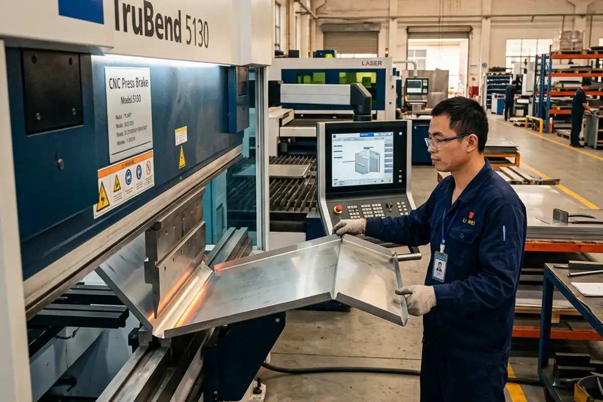
A tolerance stack is the combined variation between features that must meet in assembly. The chain may cross several bends, hardware locations, welded seams, mating panels or a finished surface. The important dimension is often not the one that is easiest to measure.
Begin with the assembly result: door alignment, mounting-hole position, gasket compression, rail spacing, connector clearance or bracket fit. Work backward to the formed features that control it.
| Planning input | Buyer question | Why it changes the stack |
|---|---|---|
| Functional feature | Which interface must fit, seal, align or clear? | It determines which dimensions deserve control and which can remain general. |
| Datum scheme | What surfaces or features locate the part in assembly and inspection? | A weak datum plan can hide where variation actually enters the assembly. |
| Measurement condition | Is the part checked free, restrained, welded, coated or assembled? | Thin formed parts can sit differently before and after restraint or downstream processing. |
| Process route | Which bends, welds, hardware and finishing steps occur before acceptance? | Later operations may move, cover or distort the feature being controlled. |
Variables that move a formed dimension
DFM checks before the flat pattern is released
| Feature | DFM risk | Practical review |
|---|---|---|
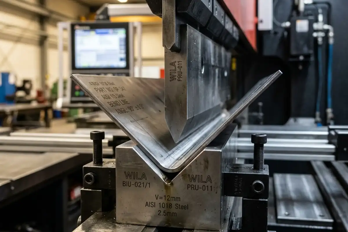
| Hole near a bend | Stretching, ovality or local distortion. | Check actual material, bend method, hole distance and whether relief or post-form work is appropriate. |
| Short return flange | Insufficient die support or tool interference. | Confirm the proposed tooling and minimum flange condition before approving the flat pattern. |
| Dimension across bends | Several angular and linear variations accumulate. | Dimension from functional datums and avoid tightening every intermediate feature. |
| Closed channel or deep box | Part collision or inaccessible final bends. | Simulate sequence, tool clearance and handling before cutting production blanks. |
| Cosmetic face | Tool marks, scratches or handling damage. | Identify visible zones and agree protective film, tooling contact and acceptance criteria. |
The springback and bend-sequence guide covers material behavior and tool access in more detail. For the commercial manufacturing scope, use the CNC sheet metal bending services page.
Do not confuse angle control with assembly fit
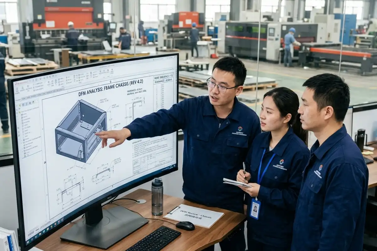
An acceptable bend angle does not guarantee that a hole pattern, cover width or door return lands in the correct place. Conversely, a functional formed dimension may be acceptable even when a noncritical intermediate angle varies within the agreed process window.
Define the acceptance feature directly. Use profile, position, linear dimensions, angular dimensions or a functional fixture only where each method makes sense. The drawing and inspection plan should agree on the same condition.
Build the first-article plan around risk
| Buyer concern | Evidence to agree | Weak instruction |
|---|---|---|
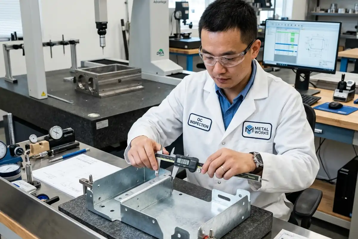
| Critical formed size | Drawing characteristic, datum reference, measurement method and result. | “Check all bends carefully.” |
| Angle or flange drift | Approved first article and a repeatable in-process check tied to the feature. | “The machine is accurate.” |
| Assembly fit | Mating-part information, gauge or buyer-approved trial assembly where required. | “It matches CAD.” |
| Finished condition | Specify whether acceptance occurs before or after welding, hardware, coating or restraint. | “Measure whenever convenient.” |
What to send with the RFQ
- A STEP or STP model and controlled 2D drawing with revision.
- Material grade, temper or condition, thickness and substitution restrictions.
- Inside radii, bend direction, visible faces and grain requirements where relevant.
- Functional datums, mating interfaces and critical formed dimensions.
- Welding, hardware, finish and assembly steps that affect the measured condition.
- First-article, sampling, report and packing requirements.
For broader supplier process controls, see the sheet metal bending process-control guide.

Frequently asked questions
What is a realistic sheet metal bending tolerance?
There is no useful universal value. It depends on material, thickness, bend method, tooling, flange length, part size, datum scheme, sequence and measurement condition. Define the functional feature and ask the supplier to confirm capability for that part.
Should every formed dimension have a tight tolerance?
No. Tighten dimensions that control fit, sealing, safety or assembly, and leave noncritical features enough room for process variation. Blanket tolerances increase inspection and rework without necessarily improving the product.
Is K-factor the same for every supplier and material?
No. K-factor is a flat-pattern planning input affected by the material and forming baseline. The production supplier should validate the value used for the approved route rather than treating one chart as universal.
Why can a bent part pass angle inspection but fail assembly?
Assembly fit may depend on flange position, accumulated dimensions, hole location, twist, welding or restraint. Angle is only one part of the tolerance chain.
Does MSTFAB guarantee one tolerance for every bent part?
No. MSTFAB reviews capability against the released drawing, material, geometry, process route and inspection requirement. Project-specific tolerances and evidence must be agreed before production.
Send the formed-part datums, not only the flat DXF
Share the controlled 3D and 2D files, material, critical interfaces, downstream operations and evidence requirements. MSTFAB will review the drawing-based bending scope before quotation.
 WeChat Contact
 WhatsApp Me Directly