
Quick answer: An outdoor enclosure mounting interface drawing should define the installation surface, finished enclosure mass and center of gravity supplied by the buyer, mounting architecture, functional datums, bracket or standoff geometry, bolt-hole pattern, load inputs, wall clearance, cable-entry keep-outs, drainage direction, coating condition, inspection method, change-control rules, and export protection. The sheet metal fabricator can manufacture and document those drawing-controlled metal features. The OEM, site engineer, structural specialist, installer, and responsible certification team must define the applied loads, supporting structure, anchors, safety factors, installation method, environmental rating strategy, and acceptance of the completed installation.
MSTFAB manufactures unpopulated custom sheet metal enclosure shells, brackets, mounting feet, rails, bases, and mechanical parts from buyer-approved drawings. Our scope can include laser cutting, bending, welding, approved hardware installation, surface finishing, mechanical first-article inspection, production records, and export packaging. We do not manufacture finished electrical equipment, select site anchors, design the supporting wall or pole, install field wiring, certify an IP or NEMA rating, calculate the completed site’s wind or seismic capacity, or approve the finished installation.
Mounting problems are often discovered after an enclosure has already become expensive. The cabinet arrives with four neat holes, but the site has a channel frame. A rear bracket covers the bottom cable route. A pole clamp cannot reach its fastener. A powder-coated mounting slot loses just enough clearance to turn installation day into an international discussion about drill bits.
These failures rarely begin with poor laser cutting. They begin when the site interface is treated as a late accessory instead of a controlled mechanical system. Good outdoor enclosure mounting DFM translates buyer-defined installation requirements into metal geometry that can be fabricated, inspected, packed, and repeated without asking the installation crew to finish the engineering.
What Does Outdoor Enclosure Mounting Interface DFM Cover?
Outdoor enclosure mounting interface DFM is the manufacturing review of the physical features that connect an unpopulated sheet metal shell to a buyer-defined wall, frame, pole bracket, pedestal, plinth, skid, or pad. It asks whether the released geometry can be made consistently and whether the finished part can be checked against the actual installation interface.
The review does not replace structural analysis. It does not decide what wind pressure, seismic acceleration, equipment mass, cable pull, impact load, or safety factor applies. Those are design inputs from the responsible OEM and qualified project professionals. DFM begins after those inputs are translated into controlled dimensions, materials, welds, fasteners, and acceptance criteria.
The mounting interface is more than four holes
A usable interface includes the hole pattern, but it also includes the load path around that pattern. Rear-panel stiffness, bracket bends, local reinforcement, weld access, coating build, bolt-head clearance, tool access, wall gap, door swing, and cable routes can all affect whether four geometrically correct holes produce a practical installation.
Outdoor exposure changes the mechanical conversation
A machine-mounted indoor box may mainly need vibration and frame compatibility. An outdoor wall-mounted enclosure also has to avoid unintended water traps, inaccessible coated interfaces, corrosion-prone damage, and field penetrations that conflict with the buyer’s environmental strategy. For general rain shedding, gasket, corrosion, and outdoor cabinet construction, use the separate outdoor electrical enclosure guide. This article owns the mounting interface itself.
Manufacturing evidence is not installation approval
A dimensional report can show that a bracket pattern matches the approved drawing. A go/no-go fixture can show that the finished enclosure fits the buyer’s mechanical template. Neither proves that the wall, anchor, pole, concrete pad, or completed installation is structurally adequate. Good evidence answers the question it was created to answer. A caliper is useful, but it has never inspected a building.
Responsibility Matrix for an Outdoor Mounting Interface
Responsibility should be assigned before quotation. If the supplier is asked to “make the mounting strong enough” without receiving loads, substrate details, and acceptance criteria, the drawing has delegated a decision without delegating the information required to make it.
| Decision or work package | Responsible owner | Controlled output |
|---|---|---|
| Installation location, support substrate, environmental exposure, access zone, and applicable local requirements | OEM, end user, site engineer, and qualified local professionals | Approved site and installation specification |
| Installed mass, center of gravity, static and dynamic loads, wind or seismic inputs, load combinations, and safety factors | OEM and qualified structural or mechanical engineer | Released design loads and acceptance criteria |
| Anchor type, embedment, torque, wall or pole capacity, field installation, and final inspection | Site engineer and qualified installer | Approved anchor and installation plan |
| Bracket, foot, rail, standoff, base, hole, slot, reinforcement, weld, and coating geometry | OEM defines; MSTFAB manufactures from approved drawings | Unpopulated enclosure shell and mechanical records |
| DFM for cutting, forming, welding, fixturing, finishing, inspection access, and packing | MSTFAB, with buyer approval for design changes | Documented questions, proposals, and approved deviations |
| IP, NEMA Type, product safety, structural, and installation conformity of the completed equipment | OEM and responsible certification or conformity organization | Applicable test and release evidence |
Start With the Site Interface and Buyer-Defined Loads
The enclosure model should not be the only model used in mounting review. Ask for the relevant portion of the wall, machine frame, structural channel, pole bracket, pedestal, plinth, or concrete pad. A simplified interface model is often enough when it clearly shows datums, keep-outs, fastener access, and adjacent structures.
Identify the support before designing the bracket
A flat concrete wall, slotted channel frame, welded skid, round pole, and raised pedestal do not present the same geometry. Define the real interface, including uneven surfaces, stand-off requirements, corrosion isolation, drainage space, and installation sequence. A so-called universal bracket is useful only when the approved range of interfaces is actually defined.
Release mass, center of gravity, and load cases
The empty enclosure mass is not the installed mass. The buyer should provide the expected completed mass, center of gravity, service loads, cable loads, door-open condition, lifting or transport conditions where relevant, and any qualified wind or seismic inputs. MSTFAB can use those approved inputs to review manufacturability of the specified metal geometry. We do not invent the site’s design basis from cabinet dimensions.
Provide an installation envelope, not a hopeful photograph
Photographs help explain context, but the controlled package should show wall returns, columns, neighboring cabinets, guards, pipework, cable trays, door sweep, tool access, and installation approach. A photograph with a red arrow labeled “cabinet here” is a fine conversation starter. It is not yet a manufacturing datum.
Choose the Mounting Architecture Deliberately
Mounting architecture should match the installation and environmental strategy. External welded feet may keep anchor holes outside the protected cavity. Rear rails can spread loads and create wall clearance. A plinth can establish a controlled base interface. Separate pole-clamp components can isolate site variability from the enclosure shell. Each route has different fabrication and inspection consequences.
| Mounting route | Useful when | DFM questions to resolve |
|---|---|---|
| External welded feet or tabs | Wall or frame mounting requires an accessible external bolt pattern | Load path, local reinforcement, weld distortion, coating access, tool clearance, and packing protection |
| Rear rails or stand-off channels | The enclosure needs distributed support or controlled wall clearance | Rail straightness, drainage, cable route, fastener access, weld sequence, and rear-plane relationship |
| Buyer-approved through-wall interface | The design intentionally uses penetrations through the enclosure wall | Hole geometry, hardware stack, sealing responsibility, coating condition, and final environmental evaluation |
| Pole-clamp interface | A separate clamp set connects the shell to a defined pole range | Pole range, rotation control, clamp access, local reinforcement, isolation materials, and responsible structural approval |
| Pedestal, base, or plinth | A floor-standing cabinet mounts to a pad, skid, or raised base | Anchor pattern, cable opening, contact plane, flatness, drainage, service access, and installation sequence |
External brackets can reduce unnecessary penetrations
An external mounting foot can keep an anchor bolt outside the enclosure cavity, but it does not automatically create an environmental rating. The OEM must still define the complete boundary, weld configuration, coating system, accessories, and evaluation route. The bracket’s first job is to transfer load. Becoming a self-appointed certification mark is not in its job description.
Through-wall fasteners need a complete interface detail
If the approved design includes a wall penetration, show every physical element that affects fabrication: hole or slot size, reinforcement, hardware stack, washer seat, gasket or seal location if supplied by others, coating mask, keep-out, and access. Do not write only “seal after installation” and expect the metal drawing to explain who provides what.
Separate enclosure fabrication from site-variable hardware
Where pole diameter, masonry condition, field channel spacing, or local anchors vary, it may be useful to define a stable enclosure-side interface and manage site-specific hardware separately. This reduces uncontrolled changes to the shell. The buyer and site engineer must still approve compatibility and capacity.
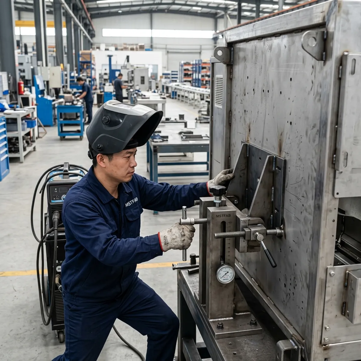
Define Functional Datums and Mounting-Hole Patterns
Mounting dimensions should originate from surfaces that matter at installation. The ASME Y14.5 dimensioning and tolerancing framework provides a common language for datums and geometric controls, but the buyer must decide which edition and requirements apply to the project.
Reference the installed interface
Useful datums may include the rear support plane, bottom mounting plane, cabinet center plane, base contact surface, or buyer-defined installation rail. Avoid locating the anchor pattern through a long chain involving cosmetic door gaps, removable panels, and unrelated bends. The wall does not care how the title block reached the dimension.
Treat holes and slots as one functional pattern
Specify horizontal and vertical pitch, true position or other approved pattern control, hole diameter, slot length and direction, and the locating strategy. If two round holes locate and two slots absorb installation variation, say so. Turning every hole into a generous slot may ease assembly while removing the location control the system needed.
Inspect the finished pattern
Laser-cut accuracy alone does not predict the delivered pattern. Bending, welding, grinding, pretreatment, and coating can alter bracket position or usable clearance. Inspection should occur after the last process capable of changing the characteristic. The customer installs the finished enclosure, not its optimistic flat pattern.
Design Brackets and Standoffs for Sheet Metal Fabrication
Bracket stiffness depends on geometry, material, thickness, unsupported length, bend orientation, weld layout, and the buyer-defined load case. A thicker flat tab is not always the best solution. Return flanges, channels, ribs, gussets, and wider load-spreading attachments can improve behavior while controlling mass and fabrication complexity.
Put stiffness where the load travels
Follow the buyer-approved load path from enclosure body to reinforcement, bracket, fastener, and supporting structure. A very thick bracket welded to a large unsupported rear sheet can simply move the deformation into the panel. The bracket looks heroic while the back panel quietly becomes the weak member.
Check bend and weld access early
Confirm minimum flange sizes, bend reliefs, press-brake tool access, weld-gun access, inspection access, and coating reach. A bracket that works only before the adjacent enclosure flange is formed needs a documented manufacturing sequence. If the sequence requires three operators and a philosophical discussion, the geometry probably deserves another review.
Control the rear stand-off distance
Rear clearance may support drainage, cable routing, bolt access, uneven-wall tolerance, heat transfer assumptions, or service access. Define the finished stand-off distance and its datum. Do not let bolt heads, weld bead, and coating thickness negotiate the final wall gap independently.
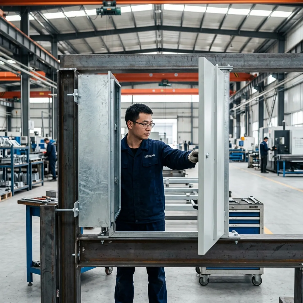
Manage Welding Distortion and the Mechanical Load Path
External brackets often concentrate heat and restraint near a large rear panel. The welded assembly may move even when every loose component was cut correctly. DFM should define the sequence, fixture concept, weld size and location, reinforcement, and finished-state characteristics that matter to installation.
Fixture from the functional datum
A repeat-production fixture should locate brackets from the same rear plane, centerline, or base surface used by the customer’s interface. Locating from a convenient cosmetic edge can make welding easy and installation inconsistent. Fixture verification and maintenance should be included when the mounting pattern is a critical-to-quality characteristic.
Balance weld access, strength inputs, and distortion
The buyer or responsible engineer defines required joint performance. MSTFAB can review whether the specified weld is accessible, repeatable, and compatible with the material and finish plan. More weld is not automatically better if it pulls the rear panel out of plane or blocks coating drainage. Welding is excellent at joining metal and equally willing to rearrange geometry.
Measure after welding and after finishing
Use staged controls where risk justifies them: bracket location after tack-up, pattern after final welding, and usable hole or slot condition after coating. This helps identify which process created drift. Final acceptance should still use the condition received by the customer.
Keep Mounting Decisions Aligned With the Environmental Boundary
The physical mounting arrangement can interact with water shedding, corrosion protection, and enclosure penetrations, but a fabricator should not convert that observation into an unsupported IP or NEMA claim. The responsible OEM defines the target, applicable standard, test configuration, accessories, and certification route.
Avoid uncontrolled field drilling
A field hole may disturb coating, create a corrosion site, conflict with internal hardware, or change the enclosure boundary used in the product’s evaluation. Where possible, freeze the mounting method before fabrication and place approved features on the controlled drawing. The installation drill should be a tool, not an undocumented engineering department.
Do not treat IP and NEMA Type labels as interchangeable
IEC 60529 defines the IP Code for degrees of protection provided by enclosures; buyers can consult the official IEC 60529 publication page. NEMA enclosure Type designations cover a different framework and must be selected and evaluated by the responsible product team. The separate IP66 versus NEMA 4X guide explains why a short label should not replace a released requirement.
Assign sealing details explicitly
For a buyer-approved through-wall mounting interface, identify who supplies seals, washers, bushings, or other components; what surface condition is required; what dimensions MSTFAB inspects; and who performs final assembly and testing. A note saying “weatherproof” is not a complete bill of responsibilities.
Coordinate Mounting, Cable Entry, Drainage, and Door Access
Mounting cannot be reviewed in isolation because the same rear and bottom zones often carry gland plates, conduits, drains, vents, hinges, latches, and service access. Overlay the enclosure, supporting structure, cable route, and service envelope in one mechanical review.
Protect cable-entry keep-outs
A rear rail or base bracket can block conduit bends, gland-nut access, cable pulling, or removable gland plates. Define cable-entry keep-outs and access tools before freezing bracket locations. For detailed enclosure-side cutouts and plate interfaces, see the cable-entry and gland-plate DFM guide.
Avoid water and debris traps
Horizontal mounting ledges, closed rear channels, and poorly oriented gussets can hold water or debris against the enclosure. The buyer should approve drainage and environmental geometry. MSTFAB can identify fabrication features that create closed pockets and propose open, sloped, or drain-friendly alternatives for approval.
Check the installed door and service envelope
A door that opens fully in free CAD space may strike a wall return, pole, neighboring cabinet, guard, or structural column. Include hinge projection, latch sweep, door stay, tool access, removable panel path, and technician reach. “The door opens in our factory” is encouraging but not a site-interface specification.
Specify Materials, Coatings, and Contact Surfaces
Material and finish selection belong to the buyer’s structural, corrosion, cosmetic, and compliance strategy. MSTFAB can manufacture approved carbon steel, zinc-coated steel, stainless steel, aluminum, and specified finishing systems within the released drawing and purchase requirements.
Define the delivered condition of holes and threads
Coating build can reduce bolt-hole, slot, weld-nut, insert, or tapped-hole clearance. State which threads require masking or chasing, which holes receive full coating, and what finished gauge or approved fastener verifies function. A hole can remain visibly round while becoming professionally inconvenient.
Do not expose bare metal without a reason
Mounting contact faces may be fully coated, selectively masked, plated, isolated, or otherwise treated according to the buyer’s design. Bare metal is not automatically required for a structural attachment, and it can create corrosion risk. If electrical bonding is intended, define that requirement separately with the responsible electrical team.
Control edges, weld zones, and mixed-material interfaces
Bracket edges and weld transitions can be difficult coating locations. DFM should review edge preparation, drain orientation during pretreatment, masking, touch-up rules, and approved appearance. Mixed stainless, carbon steel, aluminum, plated fasteners, or site structures also require buyer review for corrosion compatibility. More detail on available finishing processes is provided on the sheet metal surface treatment page.

Wall, Frame, Pole, and Pedestal Mounting Scenarios
Different installations can share fabrication processes without sharing design assumptions. The buyer should select the architecture and provide its loads and interfaces. MSTFAB then reviews how the approved parts can be cut, bent, welded, finished, inspected, and packed.
Wall-mounted enclosure shells
Define wall plane, rear gap, anchor pattern, bracket access, cable approach, drainage, door clearance, and the complete installed mass. External feet or rails may be appropriate when approved. The wall-mount electrical enclosure fabrication page covers the broader enclosure type; this article remains focused on its physical mounting interface.
Frame-mounted and machine-adjacent shells
Provide frame members, bolt pattern, equipment vibration inputs, access zones, cable forces, and neighboring guards. When the enclosure is attached directly to machinery and vibration is a primary requirement, use the separate machine-mounted enclosure DFM guide for that intent.
Pole-mounted enclosure shells
Define pole diameter or range, orientation, clamp system, anti-rotation strategy, stand-off, access, applied loads, and corrosion isolation. MSTFAB can fabricate buyer-approved rear channels, brackets, and enclosure-side interfaces. Pole capacity, clamp sizing, wind response, field torque, and final approval remain with qualified responsible parties.
Pedestal, plinth, and pad-mounted cabinet shells
Control the bottom plane, anchor pattern, cable opening, access covers, contact zones, flatness or coplanarity where functional, and drainage. Anchor bolts should secure the approved geometry, not force a twisted base into shape. For deeper base-interface coverage, see the industrial enclosure base and plinth DFM guide.
First-Article Inspection for Mounting Interfaces
A first article should answer whether the delivered enclosure fits the buyer’s interface and whether critical features survived welding and finishing. The inspection plan should be proportional to risk, volume, field service cost, and the difficulty of detecting an error after export.
| Characteristic | Practical evidence | Acceptance owner |
|---|---|---|
| Mounting-hole or slot pattern | Coordinate measurement, calibrated fixture, or buyer-approved checking template on the finished enclosure | MSTFAB records; buyer approves criteria |
| Rear stand-off or base plane | Datum-based dimensional report, surface plate method, or approved representative interface | MSTFAB within drawing scope |
| Bracket angle, weld location, and local distortion | Visual and dimensional inspection after welding and after finishing where relevant | MSTFAB within approved drawing |
| Door, latch, cable, and tool clearance | Representative frame, installation envelope, or approved digital/physical fit check | Buyer defines envelope; MSTFAB checks specified features |
| Coating, masks, holes, and threads | Finished-state photographs, gauges, and approved fastener checks | MSTFAB within finish specification |
| Anchor, wall, pole, wind, seismic, and final installation capacity | Project-specific engineering and site records | OEM, site engineer, installer, or responsible authority |
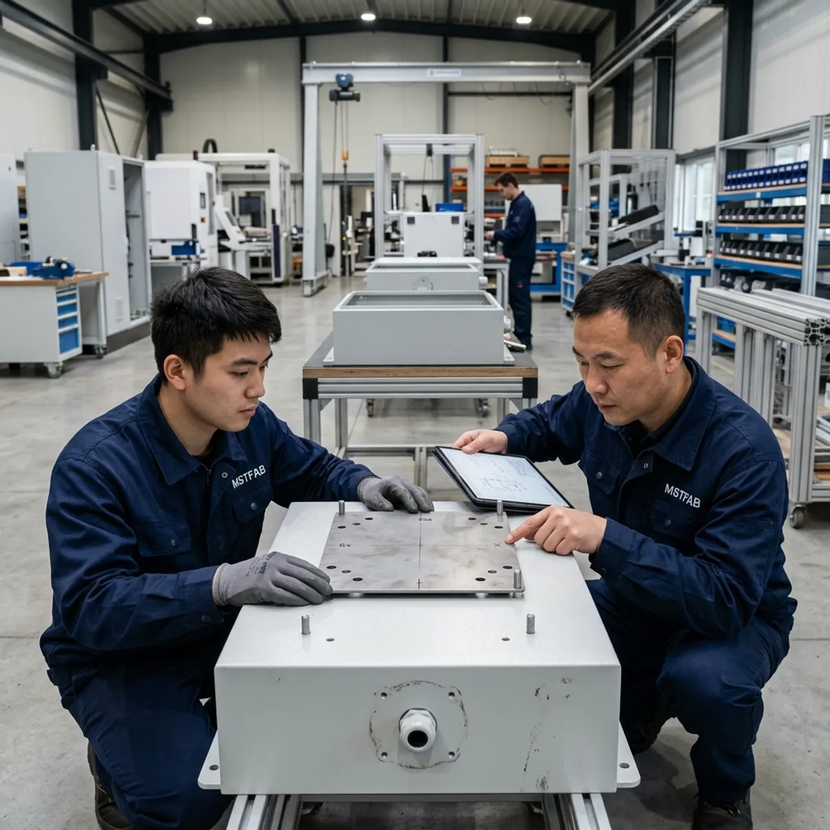
Use a representative mounting template
A simple steel or aluminum checking plate can represent the buyer’s anchor pattern and support plane. It gives production and incoming inspection a direct fit test. The template itself must be controlled, identified, verified, and protected from damage. An inaccurate master fixture creates very consistent wrong parts.
Record datums, methods, and finished condition
A report should identify the drawing revision, part revision, measurement stage, datum setup, equipment or fixture ID, measured values, acceptance criteria, inspector, date, and result. Photographs should use consistent views and include labels or scales where useful. “Looks good” is friendly; it is not especially searchable during a field investigation.
Keep evidence proportional to risk
A small four-hole wall box and a large pole-mounted cabinet do not need identical evidence packages. Agree CTQs before quotation. Concentrate measurement effort on pattern fit, load-path geometry, finished clearances, and features expensive to correct after coating or shipment.
Separate mechanical fit from final structural verification
MSTFAB can verify that the unpopulated enclosure’s drawing-defined bracket and hole geometry matches the approved requirements. The responsible project team must verify anchors, supporting structure, applied loads, completed mass, installation workmanship, and final site performance. A bracket can match its drawing perfectly and still be connected to the wrong wall.
Control Repeat Production and Engineering Changes
Mounting interfaces are sensitive to small changes because they connect to site hardware that may already exist. A bracket supplier change, bend-radius update, weld-sequence adjustment, coating substitution, hole-size change, or packaging revision can alter fit even when the enclosure still looks familiar.
Identify mounting CTQs in the control plan
Typical CTQs include anchor pattern, bracket spacing, rear stand-off, base plane, hole or slot condition after coating, weld location, and relationship to door or cable keep-outs. Do not apply the tightest tolerance to every cabinet dimension. Control the features that make installation succeed.
Link fixtures and gauges to the drawing revision
When the buyer changes a bracket or site pattern, review every affected fixture, checking plate, inspection program, work instruction, packing support, and approved sample. A revised CAD file does not automatically walk through the factory updating old gauges. Change control has to perform that less glamorous but essential work.
Return approved field corrections to the controlled model
If an installation team moves a hole, adds a spacer, rotates a rail, or changes a bracket, the responsible OEM should review the change and update the released package when accepted. Otherwise the next production batch faithfully repeats the old design and everyone gets to rediscover the same site lesson.
Protect Mounting Features During Export Packaging
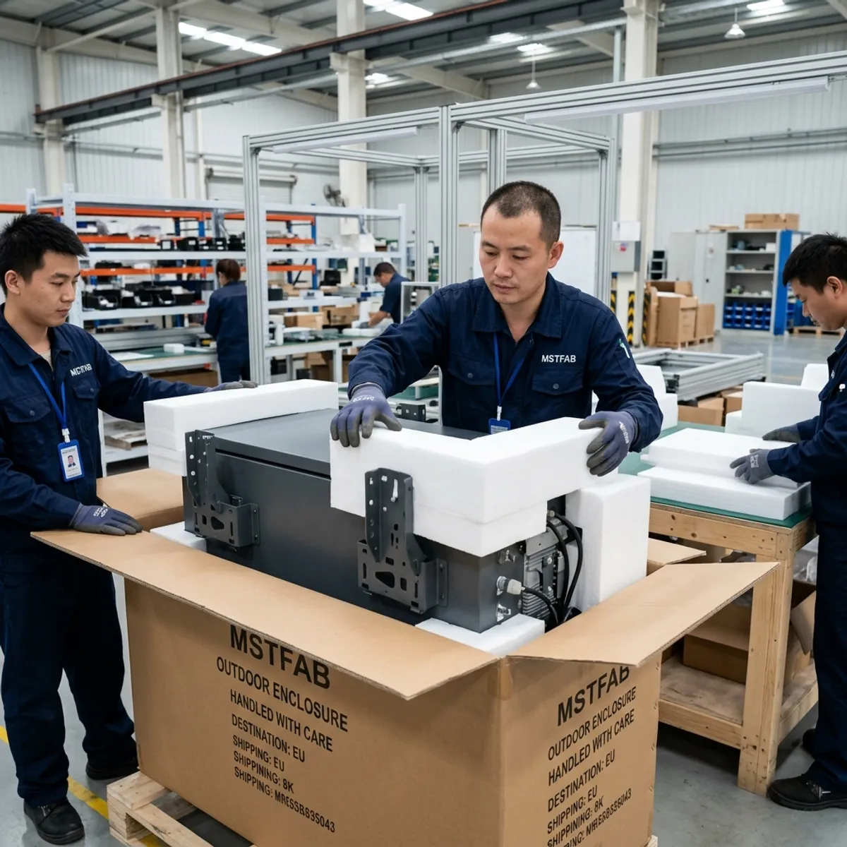
External ears, rails, standoffs, and base corners are load-bearing features at installation and vulnerable projections during transport. Packaging should prevent bending, abrasion, trapped moisture, thread damage, and load transfer through unsupported brackets.
Keep pallet and strap loads off protruding brackets
Use rigid supports and blocks that carry shipping loads through approved structural areas. Do not let strapping pull directly across a mounting ear or rear rail. The bracket should arrive at the buyer with the angle shown on the drawing, not a new angle proposed by ocean freight.
Protect finished surfaces, holes, and threads
Separate coated or stainless surfaces from metal-to-metal contact. Use approved caps, sleeves, films, foam, or corrosion protection that does not leave harmful residue on functional interfaces. Make protection visible and removable without scratching the delivered part.
Make receiving inspection practical
Pack the enclosure so the buyer can inspect mounting features without dismantling the entire shipment. Label loose bracket kits, fastener packs, and controlled templates by part and revision. More detail on shipment methods is available on the sheet metal assembly and export packaging page.
RFQ Checklist for Outdoor Enclosure Mounting DFM
A useful RFQ does not need a long presentation. It needs controlled inputs that let engineering, production, quality, and purchasing discuss the same interface.
| RFQ input | What the buyer should provide | Why it matters |
|---|---|---|
| Installation interface | Wall, frame, pole, pedestal, plinth, skid, or pad model with datums and keep-outs | Prevents bracket and access assumptions |
| Loads and responsibility | Completed mass, center of gravity, approved load cases, safety criteria, and responsible engineering owner | Separates structural design inputs from fabrication DFM |
| Mounting definition | Architecture, bracket drawings, hole pattern, slots, standoffs, reinforcement, welds, and permitted substitutions | Creates a manufacturable and auditable interface |
| Environmental strategy | Exposure, material, coating, masks, penetrations, drainage direction, and applicable rating or test plan | Prevents mounting changes from conflicting with the approved boundary |
| Installation access | Anchor head, washer, nut, socket, wrench, cable, door, latch, and service envelopes | Confirms that correct geometry can actually be assembled |
| Inspection package | CTQs, datum method, template or fixture, FAI format, photographs, sample approval, and retention rules | Defines objective release evidence |
| Production and packing | Volume, change-notice needs, labels, loose kits, surface protection, pallet limits, and shipping route | Protects repeatability through delivery |
For quotation, include 3D files, 2D drawings, bracket details, finish specification, estimated volumes, inspection requirements, installation interface, and packaging expectations. MSTFAB can then review the approved metal work for cutting, bending, welding, finishing, inspection, and export. The broader service scope is described on the custom electrical enclosure fabrication from drawings page.
Frequently Asked Questions
Does MSTFAB design the outdoor enclosure mounting system?
No. The OEM and qualified project professionals define the installation architecture, applied loads, support, anchors, safety factors, and acceptance criteria. MSTFAB reviews and manufactures the buyer-approved sheet metal shell, brackets, rails, feet, standoffs, bases, welds, holes, and finishes.
Can MSTFAB select wall anchors or pole clamps?
No. Anchor and clamp selection depends on the substrate, pole, loads, installation conditions, local requirements, and responsible engineering approval. MSTFAB can fabricate the drawing-defined enclosure-side metal interface and approved loose sheet metal bracket components.
Are external welded brackets automatically waterproof?
No. External brackets may help avoid unnecessary penetrations, but environmental performance depends on the complete enclosure construction, accessories, installation, and applicable evaluation. MSTFAB does not certify an IP or NEMA rating from bracket geometry alone.
Should mounting holes be round or slotted?
The buyer should define the locating and adjustment strategy. Round holes can provide location; controlled slots can absorb approved installation variation. Slot direction, length, width, tolerances, washer support, and finished coating condition should be stated.
How should a mounting pattern be toleranced?
Reference functional installation datums and control the pattern as a related set of features. The exact tolerancing method and values depend on the buyer’s interface, site variation, assembly method, and applicable drawing standard.
Can MSTFAB verify wind or seismic capacity?
Not as part of ordinary drawing-based fabrication. Qualified responsible engineers define and approve wind, seismic, support, anchor, and completed-installation requirements. MSTFAB can provide mechanical fabrication records for the unpopulated drawing-defined parts.
Should the rear of a wall-mounted enclosure have a gap?
Only when the buyer’s installation design requires one for drainage, cable access, uneven surfaces, hardware access, thermal assumptions, or service. The required distance, datums, tolerance, and load path should be on the controlled drawing.
When should the mounting pattern be inspected?
Inspect after processes that can change it. For welded and coated assemblies, that normally means finished-state inspection, with intermediate checks when they help control welding or diagnose drift.
What should be included in a first-article report?
Include part and drawing revision, datum setup, measured CTQs, method or fixture ID, finished-condition photographs, result, inspector, and date. Add a representative mounting-template fit check when site compatibility justifies it.
Can the installer drill mounting holes in the field?
Only under the responsible OEM’s approved installation and environmental strategy. Uncontrolled drilling can affect coating, corrosion resistance, internal clearances, and the evaluated enclosure boundary.
Does MSTFAB supply a finished outdoor electrical cabinet?
No. MSTFAB supplies custom unpopulated sheet metal enclosure shells and mechanical parts from approved drawings. We do not supply the completed electrical equipment, wiring, site installation, product certification, or final commissioning.
What information produces the fastest useful quotation?
Send the 3D model, 2D drawings, installation interface, bracket details, approved load inputs, materials, finish, expected quantity, CTQs, FAI needs, and packaging requirements. Clear inputs reduce assumptions and make DFM questions specific.
Conclusion: Make the Site Interface a Controlled Metal Interface
Reliable outdoor enclosure mounting begins before fabrication with a defined support, approved load inputs, functional datums, a deliberate architecture, accessible fasteners, coordinated cable and door envelopes, a finished-condition inspection plan, and packaging that protects protruding features.
MSTFAB can laser cut, bend, weld, install approved hardware, finish, mechanically inspect, document, and pack the unpopulated enclosure shell and drawing-defined mounting parts. The OEM and responsible project professionals retain ownership of loads, anchors, supporting structures, environmental performance, final installation, and completed-equipment approval.
That division of responsibility is practical, not ceremonial. It lets the factory be accountable for metal geometry and gives the site team the information it needs to approve the installation. It also keeps four innocent holes from being promoted into a complete structural engineering department.
Written by: MSTFAB Sheet Metal Engineering Team
Technical review: Fabrication and Quality Team
Last reviewed: August 2026
 WeChat Contact
 WhatsApp Me Directly