Cable entry is one of the smallest-looking details in an automation enclosure and one of the easiest places to create expensive field rework. A cutout that appears correct in a flat drawing can still be blocked by a base rail, too small for a pre-terminated connector, inaccessible to a wrench, or impossible to service after the mounting plate and wire duct are installed.
Quick answer: Automation enclosure cable entry DFM is the mechanical review of gland plates, conduit cutouts, connector openings and service clearances before sheet metal production. OEM buyers should confirm ten items: entry direction, actual connector envelope, cable bend space, removable-plate path, structural interference, mounting-plate clearance, tool access, sealing method, grounding and coating details, and first-article fit evidence. The objective is a cable-entry interface that can be manufactured, assembled, tightened, inspected and serviced without drilling or grinding the finished cabinet.
Scope note: MSTFAB manufactures drawing-based automation enclosure bodies, removable gland plates, connector panels, welded frames, mounting plates, brackets and grounding features. We do not select the buyer’s electrical system or certify a finished control panel. The OEM, panel builder or system integrator defines the cables, connectors, glands, environmental target and applicable product requirements; MSTFAB converts those approved mechanical requirements into repeatable sheet metal parts.
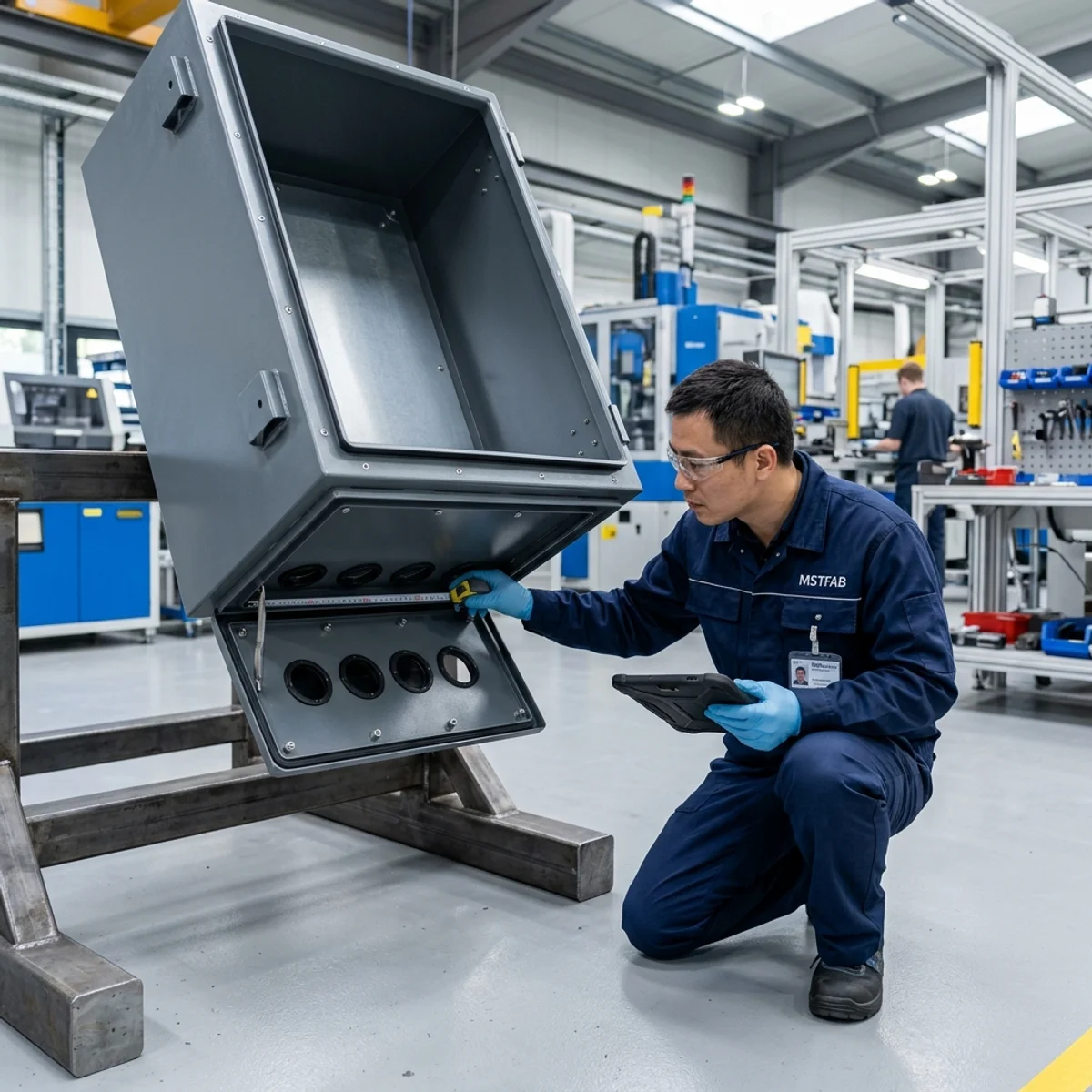
What Is Automation Enclosure Cable Entry DFM?
Automation enclosure cable entry DFM is a design-for-manufacturing and assembly review focused on how cables, conduit and connectors pass through the sheet metal enclosure. It checks more than whether a laser can cut the opening. It verifies whether the selected interface fits the manufacturing process and the complete installed assembly.
A useful review follows the physical task. Can the connector pass through the opening? Can the gland be inserted and tightened? Can a technician reach the locknut? Can a removable plate leave the cabinet without hitting a plinth or anchor? Can the cable turn toward the terminal area without violating the bend space defined by the electrical team? Can the same operation be repeated after powder coating?
| Buyer question | Design information required | Acceptable production evidence |
|---|---|---|
| Will the real connector pass through? | Connector body, boot, latch and insertion envelope | Approved CAD check, template or physical dummy fit |
| Can the gland be tightened? | Nut size, tool approach and adjacent-gland spacing | First-article installation with the intended tool |
| Can the gland plate be removed? | Removal direction, fasteners and surrounding structure | Remove-and-reinstall check on the assembled enclosure |
| Will the interface remain protected? | Gasket, sealing surface, finish and target rating | Measured metal features plus buyer-owned system validation |
| Can the design be repeated? | Controlled drawing, tolerances, part numbers and inspection plan | FAI report and approved configuration record |
Why Cable Entry Problems Appear Late
Cable entry is often detailed after the enclosure size, HMI, cooling layout and mounting plate have been selected. By then, the lower cabinet volume may already contain base channels, leveling feet, anchor points, wire duct, terminal blocks and structural brackets. The remaining open area in CAD is not necessarily a usable installation path.
Late changes affect more than one hole. Moving a gland plate may change the bottom panel, mounting plate, base frame, cable length, labeling, coating, packaging and first-article inspection. For an overseas OEM program, one unresolved opening can delay shipment or force field technicians to drill a finished enclosure. That creates uncontrolled metal swarf, damages corrosion protection and makes future units different from the approved sample.
The practical rule is simple: treat cable entry as an assembly interface before the quote, not as a workshop decision after the cabinet is complete. Include it in the initial sheet metal enclosure DFM review.
Cable Entry Architecture Comparison
The correct architecture depends on product variation, service strategy, connector size, sealing requirements and annual volume. The buyer should choose the approach before the supplier details the manufacturing route.
| Cable-entry method | Suitable application | Buyer checks before release |
|---|---|---|
| Fixed laser-cut opening | Stable cable or conduit layout | Freeze the exact cutout, edge treatment and connector envelope; reopen the review if the connector changes. |
| Removable gland plate | Configurable machines and serviceable interfaces | Define removal direction, sealing, hardware and plate variants; verify the fasteners remain accessible. |
| Pre-punched gland pattern | Repeat products using approved gland sizes | Approve the gland model, nut and tool spacing, plate stiffness and unused-hole treatment. |
| Blank field-machined plate | Site-specific cable schedules | Define the usable area, spare plates, field-machining method, sealing process and responsibility. |
The 10-Point Automation Enclosure Cable Entry Checklist
1. Confirm Entry Direction and Installation Position
Define whether cables enter from the bottom, side or top and review the enclosure in its installed orientation. Bottom entry can protect the interface, but it often competes with plinth rails, floor anchors and mounting-plate clearance. Side entry may improve access but can affect cabinet-to-cabinet spacing. Top entry can simplify routing in some systems but may introduce additional environmental and service considerations.
- Put on the drawing: entry face, orientation, usable cable zone and prohibited structural zones.
- Ask for evidence: an assembly view showing the cabinet, base frame and installation surface.
- Red flag: a note saying “cable entry as required” without controlled geometry.
2. Use the Complete Connector Envelope
Do not size the opening from cable diameter alone. A 12 mm cable may arrive with a 35 or 40 mm connector, a rigid strain-relief boot and a latch that needs lateral access. Right-angle connectors require a specific insertion direction. Shielded industrial connectors may need room for a locking collar or backshell.
- Put on the drawing: manufacturer, part number, maximum connector envelope, mating direction and cable exit.
- Ask for evidence: interference review using the approved component model or a revision-controlled dummy.
- Red flag: the supplier receives only cable diameter and is expected to choose the opening.

3. Define the Gland Plate Removal Path
A gland plate may fit its final position and still have no physical path for removal. Model the complete movement, including any tilt or rotation. Check interference with base rails, leveling feet, anchors, plinth covers, adjacent cabinets and internal brackets. Also confirm whether the plate can be removed after the enclosure is fixed to the floor or vehicle frame.
- Put on the drawing: plate outline, fastener type, installation side and required removal direction.
- Ask for evidence: first-article removal and reinstallation on the assembled enclosure.
- Red flag: the plate can be installed only before the base structure is welded or mounted.
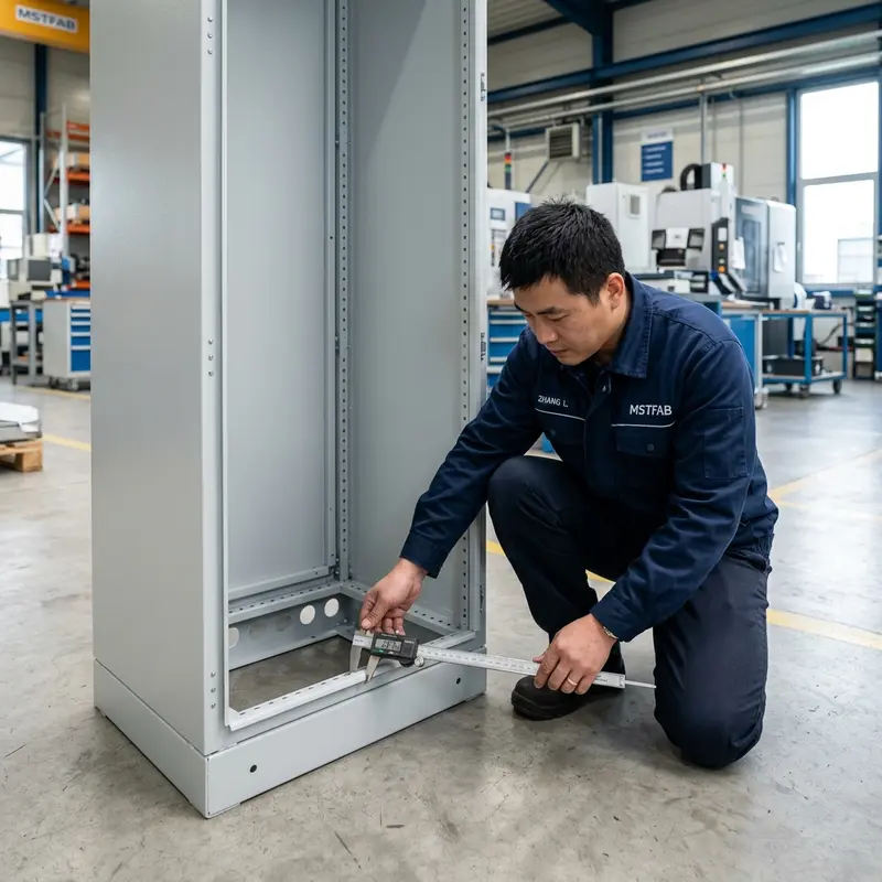
4. Keep Cutouts Clear of Bends and Structural Members
Large openings reduce panel stiffness, while holes placed too close to bends can distort during forming. The remaining material around the cutout must carry plate fasteners, gasket compression and gland loads. Coordinate cutout position with bend radii, corner relief, welds, frame members and handling loads.
- Put on the drawing: cutout datums, corner radii, edge distances and critical flatness or position requirements.
- Ask for evidence: DFM comments on forming access, remaining flange width and distortion risk.
- Red flag: a large opening crosses a bend zone or sits directly over a structural rail.
5. Coordinate the Mounting Plate and Internal Components
A mounting plate positioned too low may block gland locknuts, connector backshells or plate screws. Wire duct, terminal blocks and power supplies can occupy the cable bend path even when they do not intersect the opening itself. Review the complete internal assembly and the order in which components will be installed.
- Put on the drawing: mounting-plate position, cable keep-out zone and minimum service space.
- Ask for evidence: a section view through the cable entry, mounting plate and intended routing area.
- Red flag: glands can be installed only before the mounting plate, but no service sequence is documented.

6. Check Hand, Wrench and Screwdriver Access
CAD visibility is not tool access. A nut can be visible and still impossible to tighten. Check wrench swing, socket depth, screwdriver angle, finger clearance and the path for retrieving hardware. For compact enclosures, the tool envelope can be more restrictive than the component envelope.
There is no universal clearance value for every cable gland. Use the selected manufacturer’s dimensions, the intended tool and the surrounding assembly. If procurement needs a numeric minimum, the OEM engineering team should approve it and add it to the controlled drawing.
- Put on the drawing: service side, tool-access zone and any required installation sequence.
- Ask for evidence: physical installation using the production-representative gland and tool.
- Red flag: the locknut fits behind the panel but cannot be reached after internal assembly.
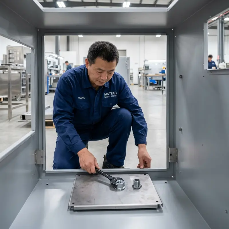
7. Define Gland Spacing and the Sealing Interface
Glands need enough spacing for locknuts, sealing washers, anti-rotation features and tools. A dense pattern can weaken a plate or leave insufficient gasket land around the perimeter. If unused holes are possible, define how they are closed. If the plate uses a gasket, specify the sealing surface, compression method, joint location and replacement strategy.
- Put on the drawing: approved gland pattern, plate thickness, gasket interface and unused-opening treatment.
- Ask for evidence: dimensional inspection of the pattern and buyer-defined sealing validation.
- Red flag: an IP or NEMA target is stated without defining the complete gland, gasket and enclosure system.
Ingress or enclosure ratings apply to a tested or evaluated assembly under defined conditions. The metal supplier controls agreed sheet metal characteristics; the certification owner, panel builder or OEM owns final system qualification.
8. Translate Grounding and Coating Intent Into Physical Details
Powder coating can insulate a grounding interface and reduce clearance around holes and plate edges. Define grounding-stud type, location and attachment method, then dimension any masked or exposed conductive area. Also identify threads, gasket surfaces and close-fitting features that require masking or coating allowance.
- Put on the drawing: grounding features, masking boundaries, finish specification and approved coating build.
- Ask for evidence: visual and dimensional confirmation after finishing, including protected threads.
- Red flag: the only instruction is “ensure grounding” with no physical fabrication requirement.

9. Specify Material, Edge Condition and Tolerances
Material and thickness influence plate stiffness, thread performance, forming and corrosion protection. Cut edges that contact cables, grommets or technicians should have an appropriate deburring requirement. Tolerances should focus on the features that control fit: cutout size and position, gland pattern, removable-plate clearance, sealing flatness and hardware location.
- Put on the drawing: material grade, thickness, finish, deburring, datums and critical tolerances.
- Ask for evidence: material verification and an FAI report listing the critical cable-entry features.
- Red flag: every dimension is tightly toleranced while the functional interfaces are not identified.
10. Inspect Removal, Installation and Fit on the First Article
Dimensional inspection proves that the part matches the drawing. A task-based first-article check proves that the assembly works. Remove the gland plate, reinstall it, fit representative hardware, tighten it with the intended tool, inspect coating clearance and confirm the connector or dummy can pass through and mate.
- Put on the inspection plan: critical dimensions, plate removal, hardware fit, tool access, coating and configuration identification.
- Ask for evidence: signed dimensional results plus photos or video of the agreed mechanical checks.
- Red flag: the report measures only plate width and hole diameter but never tests the installation task.

Use these checks together with the broader automation enclosure first article inspection checklist.
Copy-and-Paste Cable Entry Drawing Notes
The exact wording should be approved by your engineering team, but controlled notes can follow this structure:
- Cable-entry geometry shall follow the drawing revision listed on the purchase order. Changes require written buyer approval.
- Gland and connector interfaces shall be checked against the approved manufacturer model or buyer-approved checking dummy.
- The removable gland plate shall be removable and reinstallable after enclosure assembly using the defined service direction.
- Critical cutout, hole-pattern, plate-clearance and grounding dimensions shall be included in the first-article report.
- Powder coating and masking shall follow the released finish drawing. Threads and conductive grounding areas shall remain functional.
- Any conflict between the cable entry, base frame, mounting plate or internal bracket shall be reported before production.
Supplier Responsibility Matrix
| Project item | MSTFAB sheet metal scope | Buyer or integrator scope |
|---|---|---|
| Enclosure body and gland plate | Manufacture to released drawings | Define geometry, quantity and revision |
| Connector and cable selection | Check approved mechanical envelope when supplied | Select components and define routing requirements |
| Grounding features | Install, weld or mask as specified | Define bonding function and final validation |
| Environmental rating | Control contracted sheet metal and finish characteristics | Define and validate the complete enclosure system |
| First-article evidence | Provide agreed dimensional and mechanical checks | Approve the sample and complete product-level validation |
When to Ask MSTFAB for a Cable Entry DFM Review
Request a review before quotation when the enclosure uses a removable gland plate, large conduit opening, pre-terminated connector, dense gland pattern, welded base frame or restricted service envelope. Send the STEP assembly, dimensioned PDF, material and finish, gland or connector data, quantity, critical dimensions and installation constraints.
MSTFAB provides custom electrical enclosure fabrication from buyer drawings. We can review laser cutting, bending, welding, installed hardware, plate fit, coating allowance and measurable first-article checks. We will also identify decisions that must remain with the buyer, electrical integrator or certification owner.
Frequently Asked Questions
What should OEM buyers check in an automation enclosure cable-entry design?
Check entry direction, connector pass-through, cable bend space, gland spacing, plate removal direction, base-frame interference, mounting-plate clearance, tool access, sealing, grounding, coating allowance and first-article evidence. Review them in the complete assembly rather than as an isolated flat panel.
How much clearance should be left around a cable gland?
There is no universal clearance for every gland. Use the selected gland manufacturer’s dimensions, locknut envelope, adjacent-gland spacing, intended wrench or socket, cable bend requirement and sealing method. Put the approved minimum on the controlled drawing.
Should an automation enclosure use a removable gland plate?
A removable plate is useful when cable layouts vary, field machining is expected or the interface must be replaceable. It adds fasteners, sealing surfaces and configuration control, so the buyer must define removal direction, plate variants, gasket strategy and service access.
Can powder coating make a gland plate or connector opening too tight?
Yes. Coating build reduces clearance at holes, slots, plate edges and hardware interfaces. Verify production-representative fit after finishing and identify masked areas for threads, grounding or close-tolerance mating features.
Does a sheet metal enclosure automatically satisfy UL, NEMA or IEC requirements?
No. A custom metal shell is not automatically a certified finished control panel or rated enclosure. The buyer, qualified panel builder or certification owner defines the applicable requirements and validates the complete assembly. The fabricator controls the physical characteristics stated in the approved drawing and purchase specification.
What files should be sent for a cable entry DFM review?
Send a STEP assembly, dimensioned PDF, revision, material, thickness, finish, gland or connector part numbers, cable directions, installation envelope, critical tolerances, prototype and annual quantities, and the required inspection evidence. Use the MSTFAB contact page to upload your project files.
 WeChat Contact
 WhatsApp Me Directly