Quick Answer
A machine-mounted electrical enclosure can be perfectly square and still be a bad machine component. Why? Because the enclosure does not spend its life sitting peacefully on an inspection table.
It gets bolted to a machine frame, vibrated, opened for service, loaded with buyer-installed equipment, pulled by cables, supported through brackets and flanges, shipped across oceans, and repeated across multiple machine builds. The critical question is therefore not only: Is the cabinet dimensionally correct? It is: Does the cabinet connect correctly to the machine?
Before releasing a machine-mounted enclosure shell for custom fabrication, OEM buyers should freeze at least these mechanical details: Machine mounting datum, Bolt pattern, Bracket geometry, Flange thickness, Load path, Weld locations, Reinforcement, Enclosure center of gravity assumptions, Door-mounted load, Cable-induced load, Service clearance, Mounting tolerance strategy, Finished coating condition, First-article machine-interface check, and Revision control.
MSTFAB provides drawing-based custom sheet metal fabrication.
Our mechanical manufacturing scope may include: Electrical enclosure shells, Machine control enclosure bodies, Doors, Covers, Mounting brackets, Mounting flanges, Welded base frames, Reinforcement gussets, Backplates, Mounting plates, Gland plates, DIN-rail support brackets, Grounding studs, HMI openings, Fan/filter openings, PEM hardware, Welding, Powder coating, Dimensional inspection, Mechanical first-article checks, and Export packaging.
We manufacture the metal enclosure and mechanical interface.
The machine builder installs PLCs, Drives, Breakers, Relays, Terminals, Wiring, Software, and Electrical controls, and owns the completed machine design and validation. We make sure the metal box knows where it belongs. It does not need to know what the PLC is thinking.
Why Machine-Mounted Enclosures Fail Differently From Wall Cabinets
A wall-mounted electrical enclosure usually has a relatively simple mechanical interface. The wall stays where it is. Machinery is less polite.
A machine-mounted enclosure may experience repeated vibration, start-stop motion, frame deflection, door movement, cable pull, service loads, and machine relocation. The enclosure may also sit on a welded machine frame, tubular structure, robot-cell frame, conveyor support, skid, or mobile machine base.
That means the enclosure mounting system becomes part of the mechanical design. A beautiful cabinet attached through four optimistic sheet metal tabs can still become an expensive percussion instrument.
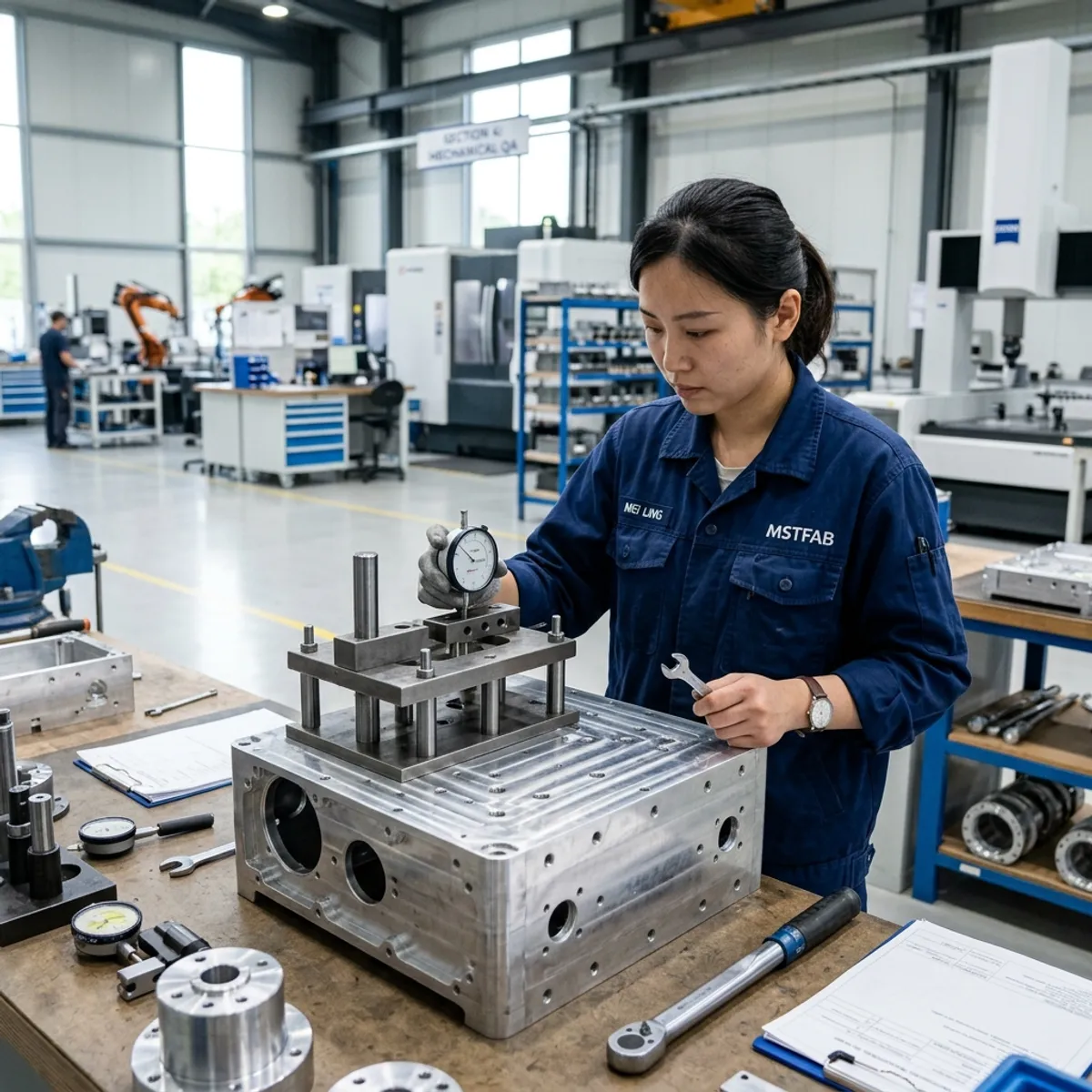
1. Start With the Machine Interface
Do not begin the enclosure mounting design with: Add four holes to the back.
Start with the actual machine. Define mounting surface, available space, machine datum, bolt pattern, orientation, and installation direction. The buyer should provide where practical the complete machine STEP model, interface drawing, hole pattern, and mounting surface geometry. The enclosure should reference the same functional coordinate system as the machine. Otherwise the machine shop can make four correct holes. The sheet metal factory can make four correct holes. They can still be correct in different universes.
2. Use Functional Datums
For a machine-mounted enclosure, the primary datum should normally relate to the actual machine interface. Possible references include machine frame surface, structural tube face, base plate, or defined machine centerline. Avoid dimensioning critical mounting holes from cosmetic enclosure features that do not control installation. The enclosure paint line may be beautiful. It is rarely a precision machine datum.
3. Control the Bolt Pattern as a Pattern
A four-hole mounting interface should not always be treated as four unrelated holes. The important requirements may include horizontal spacing, vertical spacing, pattern position, hole size, and slot direction. Depending on the OEM’s locating strategy, some holes may locate, clamp, or allow adjustment. This should be deliberate.
Four tight round holes can create assembly difficulty when the machine frame varies, welded enclosure varies, or coating adds thickness. Sometimes a controlled locating-hole-plus-slot strategy is more robust. If all four holes believe they are the primary datum, installation can become an election nobody wins.
4. Use Slots With a Defined Purpose
Slots can provide assembly adjustment. But do not use them everywhere. Define slot length, slot width, orientation, and adjustment direction. For example, vertical slots may allow height adjustment while controlling lateral position. Horizontal slots do the opposite. The orientation should follow the tolerance problem being solved. “Add slots so it fits” is useful prototype advice. Production drawings deserve more ambition.
5. Check Hole Size After Surface Finishing
Mounting holes may be affected by powder coating or other finishes. For close-fitting fastener interfaces, design around the finished condition. Do not approve the bolt fit only on bare steel and then assume several finished surfaces will remain equally generous. Powder coating is excellent at corrosion protection and appearance. It is not famous for respecting your original clearance.
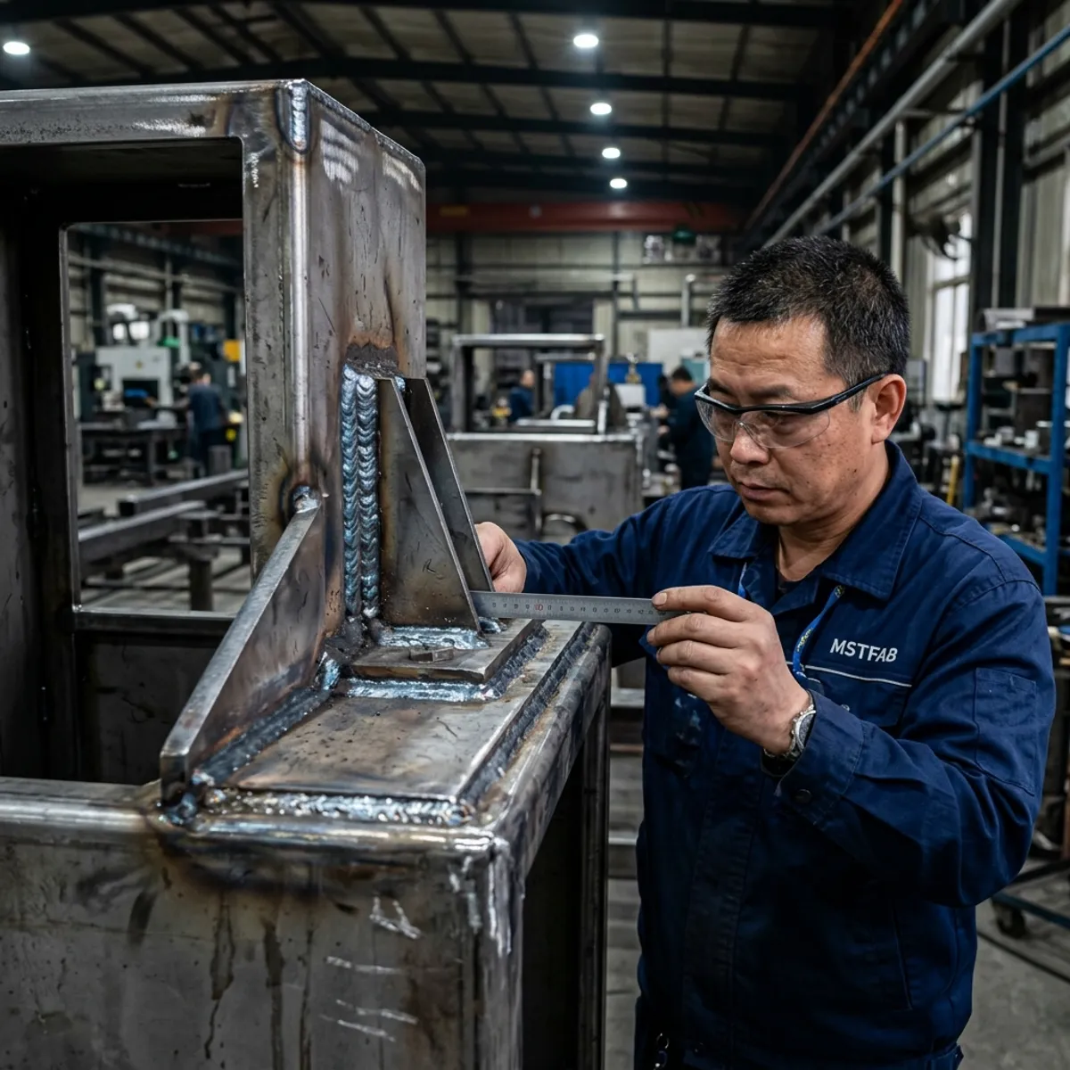
6. Do Not Mount a Heavy Cabinet Through Thin Unsupported Tabs
A common enclosure design uses bent tabs or ears for mounting. This can work well when enclosure weight is low, loads are modest, and tabs are appropriately supported. But a larger enclosure may need a reinforced flange, welded bracket, gusset, or base frame depending on the mechanical load.
The buyer should identify empty enclosure mass, estimated installed mass, door-mounted mass, and expected machine environment. MSTFAB can manufacture the approved bracket geometry. We should not guess the machine load from the cabinet dimensions. A small enclosure containing several buyer-installed drives may have very different ambitions.
7. Follow the Load Path
Every mounted enclosure transfers load through a path: Enclosure body → bracket/flange → fastener → machine frame. Review each connection. Ask: Where does the cabinet weight enter the bracket? Where does the bracket enter the enclosure? Is the sheet locally supported? Is the weld located where the load actually travels?
A thick bracket welded to a thin flexible panel may simply move the weak point. Good structure does not make one part extremely strong. It makes the complete load path sensible.
8. Bracket Bends Can Improve Stiffness
A flat bracket may be easy to laser cut. A formed bracket can sometimes provide considerably better stiffness with similar material thickness. Depending on geometry, features such as return flange, hat section, channel, or gusset can improve rigidity. Do not automatically solve bracket deflection by increasing plate thickness. Sometimes one intelligent bend contributes more than another kilogram of steel. The press brake enjoys being useful. Give it something to do.
9. Avoid Sharp Load Transitions
A mounting tab attached to a large panel through a very narrow neck can concentrate stress. Review transitions around tab roots, cut corners, slots, weld ends, and bracket-to-panel interfaces. Depending on load, use an appropriate radius, wider transition, or reinforcement as defined by the mechanical design. Sheet metal is remarkably good at explaining stress concentration after several months of vibration. Unfortunately, it explains it with a crack.
10. Welded Mounting Brackets Need Distortion Control
Welding a bracket to an enclosure introduces heat. Heat can move hole position, bracket angle, and cabinet frame. This becomes important because the machine interface may be controlled to a relatively precise bolt pattern.
For first article, inspect critical mounting geometry after welding. Do not rely only on flat-pattern hole position or pre-weld bracket inspection. The hole may have started in exactly the right place. Welding may have invited it to explore. For more on minimizing heat impacts and securing interfaces, explore our welded sheet metal fabrication capabilities.
11. Fixture Critical Brackets
For repeat production, machine-interface brackets may justify a dedicated or semi-dedicated welding fixture. A useful fixture may control bracket position, angle, and hole pattern relationship. This becomes especially useful when multiple brackets must align, the cabinet is welded, or production repeats across many machines. A complicated fixture controlling unimportant dimensions is engineering sculpture.
12. Inspect Bracket Position From the Machine Datum
Do not inspect the bracket only relative to a nearby weld seam or sheet edge. Where the mounting interface is critical, measure from the agreed functional datum. Otherwise the enclosure can pass inspection while the machine interface drifts. The part does not care what the quality report says. The bolts still have to enter the holes.
13. Vibration Is Primarily a Mechanical Interface Problem for the Fabricator
MSTFAB does not perform the buyer’s full machine vibration qualification unless separately defined. But sheet metal DFM can reduce obvious mechanical weaknesses. Review long unsupported tabs, flexible mounting flanges, heavy door loads, large unsupported panels, bracket welds, and fastener interfaces.
The OEM should provide the applicable vibration or dynamic-loading requirement where it matters. Do not send: Must resist vibration. That is a requirement emotionally. Engineering still needs load, frequency/spectrum, direction, and test requirement. The enclosure cannot negotiate with an adjective.
14. Machine Vibration Does Not Automatically Mean Thicker Steel
Increasing thickness can improve stiffness. It also increases weight, cost, bend force, and shipping mass. Before changing thickness, consider whether the real issue is a weak bracket, long unsupported span, missing return, poor load path, or large cutout. Put material where it solves the problem. Do not give every panel a gym membership because one bracket is nervous.
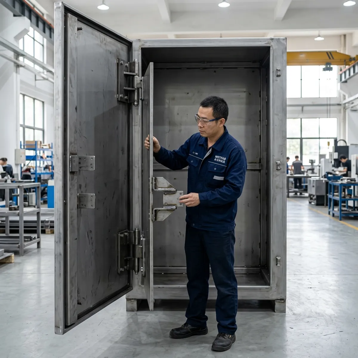
15. Large Doors Change the Mounted Load
A tall cabinet door may contain buyer-installed HMI, switch hardware, or indicators. These can shift the loaded center of gravity and create hinge load, cabinet twisting, and mounting-bracket load. The buyer should provide significant door-mounted equipment mass where relevant. The empty-door test is useful. The loaded-door condition is more representative. Gravity does not accept the argument: It closed fine before we installed the HMI.
If the human-machine interface sits on an angled console rather than a conventional cabinet door, the panel angle, reach zone, loaded door condition and service access need a combined review. See our operator console enclosure manufacturing scope for the mechanical details MSTFAB can build from the OEM’s released drawings.
16. Door Opening Can Load the Machine Interface
For some machine-mounted enclosures, the door acts like a lever when fully open. A wide door with heavy installed hardware can create moment on the cabinet frame, mounting brackets, and machine connection. Review door size, opening angle, and mounted mass where appropriate. The door is not only an access feature. When open, it can become a very polite cantilever.
17. Include the Machine Frame in Door-Swing Review
Machine enclosure CAD reviews often hide the machine to inspect the cabinet. Then the door opens perfectly. Put the machine back. Possible interference appears with guarding, robot fencing, structural tubes, or cable tray. The actual installed environment matters. A door with 120° opening in isolated CAD and 24° opening on the real machine still has hinges. It has less useful hinges.
18. Cable Pull Can Reach the Enclosure
Cables entering the enclosure may introduce mechanical loads through glands, connectors, and cable supports. MSTFAB does not design the buyer’s cable system. But cable-entry geometry should not accidentally place significant cable loads onto a thin unsupported panel. Where the OEM design requires it, the enclosure can include a reinforced gland plate, cable-support bracket, or local stiffening. The cable may be electrical. Its weight remains disappointingly mechanical.
19. Keep Machine Mounting and Cable Entry From Fighting
Bottom or rear mounting brackets can compete for space with gland plates, conduit openings, and cable brackets. Review them in one assembly. A strong lower bracket placed directly behind the cable-entry opening is an excellent structural solution to the wrong drawing.
20. Service Access Is Part of the Machine Interface
A machine-mounted cabinet may have limited surrounding access. The buyer should check whether technicians can reach the door, removable side panel, gland plate, or mounting fasteners after installation. A cabinet can be easy to assemble at MSTFAB and difficult to service on the customer’s machine. The factory floor has generous open space. Machines are less charitable.
21. Decide Whether the Enclosure Must Be Removable From the Machine
Some machines are designed so the electrical enclosure can be removed as a unit. Others treat it as a long-term structural installation. If removal is required, review fastener access, lifting, cable-disconnection interface, and removal direction. MSTFAB controls only the mechanical sheet metal elements defined by the buyer. But the mounting bracket should support the intended maintenance strategy.
22. Add Lifting Features Only When Properly Defined
Larger enclosure shells may use buyer-defined lifting eyes, lifting brackets, or fork pockets. These are structural features. The OEM should specify the design loads and approved lifting method. MSTFAB can fabricate the drawing-defined metalwork. Do not add an M10 eyebolt because the cabinet looks heavy. Lifting hardware is not decorative. Gravity is an aggressive auditor.
23. Machine Mounting Brackets and Transport Brackets Are Different
A bracket designed for normal operating loads may not automatically be appropriate for shipping restraint or lifting. If temporary shipping brackets are needed, give them a separate part number, installation instruction, and removal instruction. Do not rely on the machine mounting ear to perform every structural job from Guangzhou to final commissioning.
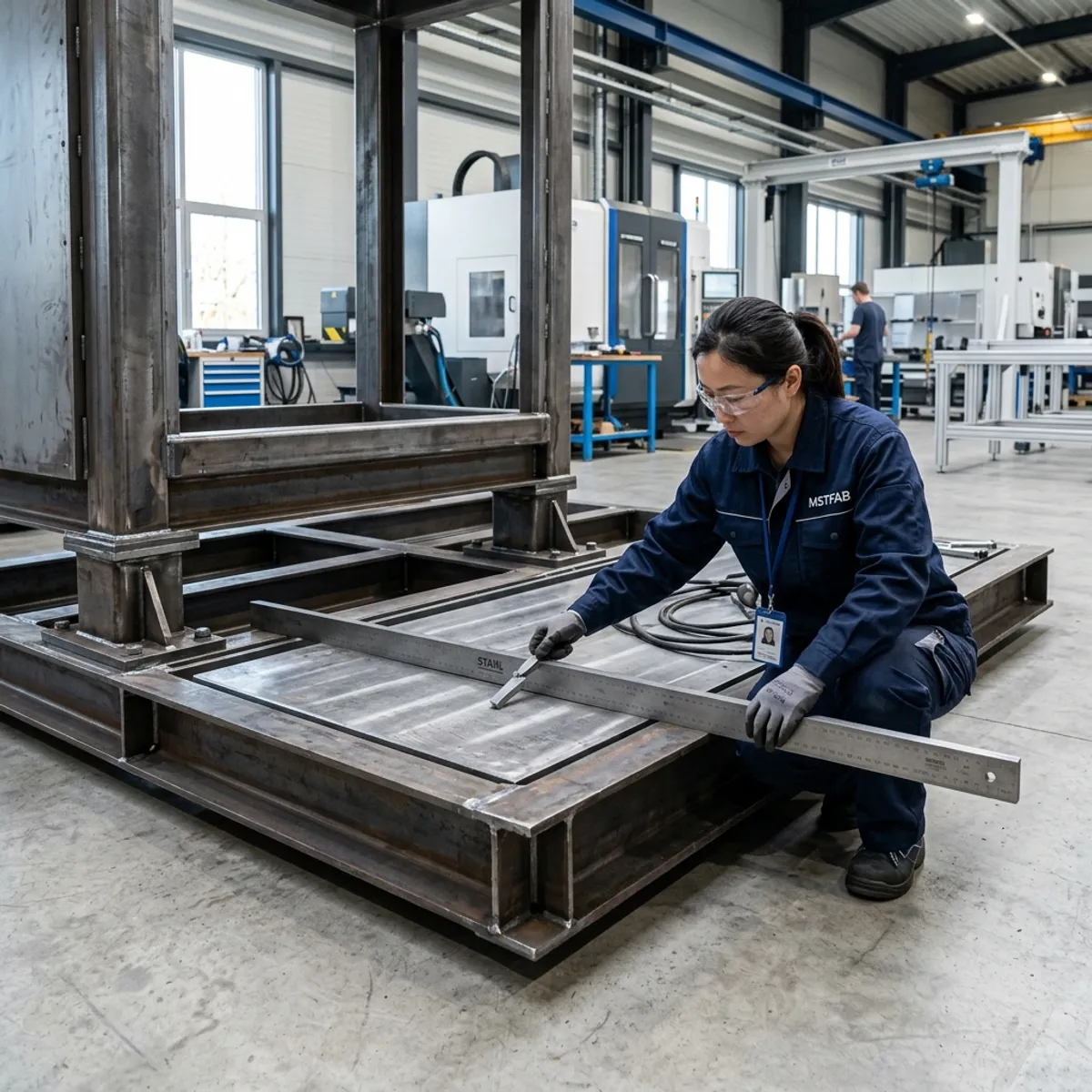
24. Base Frames Need Flatness and Squareness
Floor or skid-mounted enclosure frames can create installation problems if the base is twisted, mounting feet are not coplanar, or the bolt pattern shifts. For welded bases, inspect after welding. Depending on the interface, useful checks may include overall dimensions, diagonals, mounting-hole pattern, and contact plane. Do not force a twisted base flat using anchor bolts unless the design explicitly expects that behavior. Fasteners are for fastening. They should not become emergency hydraulic presses.
25. Powder Coating Must Not Hide Machine Datums
Where a bracket contacts a machine surface, the OEM should define whether the interface is coated, masked, or otherwise finished according to its mechanical/corrosion design. There is no universal rule that mounting surfaces must be bare. The drawing should specify the required condition. Do not let production decide from “looks important.” Important features deserve dimensions and notes.
26. Hardware Selection Needs Mechanical Context
Machine-mounted enclosures may use weld nuts, PEM nuts, rivet nuts, or through bolts. The correct choice depends on sheet thickness, access, load, and service frequency. MSTFAB can manufacture the selected hardware interface. For critical mounting points, review whether the hardware is suitable for the required mechanical load rather than choosing it only because it provides the desired thread. M8 is a thread size. It is not a structural calculation.
27. Do Not Rely on Ordinary Sheet Metal Screws for Everything
Primary machine mounting generally deserves a clearly defined structural connection. The buyer should control fastener type, grade, washer, nut/insert, and torque requirement where applicable. MSTFAB’s job is to provide the defined metal interface. We do not need to pretend every screw in a cabinet performs the same job. Neither does the screw.
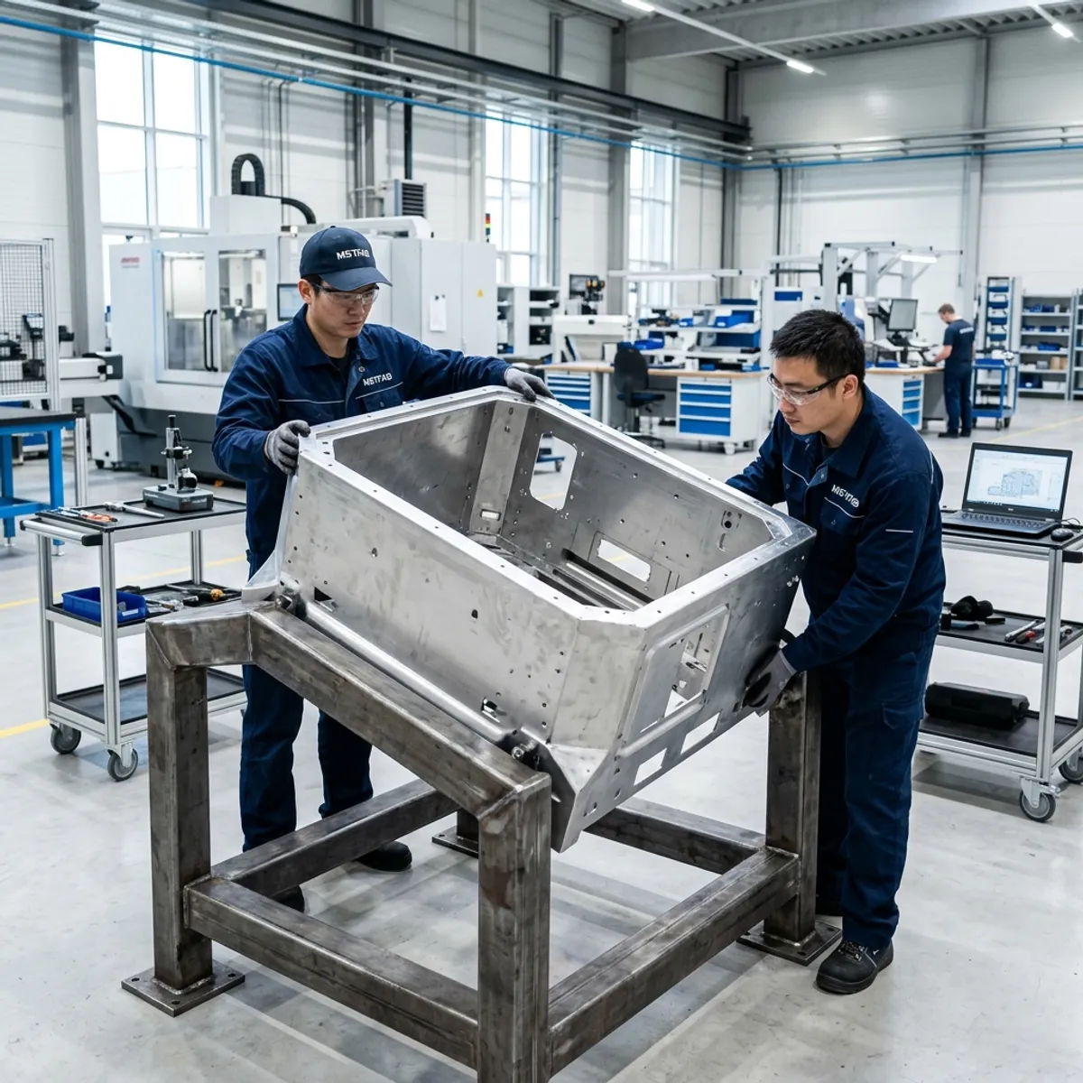
28. First Article Should Include a Machine-Interface Fixture
For a repeat machine-mounted enclosure program, a checking fixture can provide strong evidence. The fixture may represent the machine mounting plane, bolt pattern, and critical locating features. The finished first-article enclosure can be installed onto it. A coordinate report can say all four holes are correct. The fixture can answer the question procurement ultimately cares about: Does the cabinet bolt onto the machine? Very efficient meeting. No PowerPoint required.
29. Check the Finished Enclosure, Not Only Bare Weldment
The final machine interface may be affected by welding, grinding, powder coating, and hardware installation. Therefore first-article approval should represent the final delivered state where practical. Check bolt pattern, bracket location, finished clearance, door operation, threads, and machine-interface fit. Bare metal is an important milestone. The customer normally purchases the version with paint.
30. Record the Interface as CTQs
Critical-to-quality features may include primary machine datum, bolt spacing, mounting flange position, bracket angle, base flatness, and door-to-machine clearance. Do not mark every dimension on the cabinet as equally critical. If 117 dimensions are all marked “CRITICAL,” the drawing has mainly proved that capital letters are available.
31. Automotive Factory Use Does Not Automatically Create IATF Applicability
IATF 16949 is built around automotive production and service-part supply chains and applicable manufacturing/finishing organizations. It should not be summarized as: Machine is automotive + enclosure is on machine BOM = enclosure supplier must be IATF 16949. Customer-specific rules can classify tooling and equipment suppliers differently. The correct questions are: What is the supplied product? What does the customer’s CSR require?
32. A Customer Can Still Require Automotive-Style Controls
Even when IATF certification is not the applicable requirement for a machine enclosure supplier, the buyer may still contractually request PFMEA, control plan, first-article inspection, capability evidence, change notification, or selected PPAP-style documents depending on the project. Those should be handled as customer/project requirements. For a deeper understanding of automotive specific rules, see our automotive enclosure change control guide.
33. PPAP Should Be Proportionate
For some machinery programs, the buyer may request a formal submission package. For others, a more proportionate package may include approved drawing, dimensional report, material certificate, finish record, mechanical fit photos, and change-control agreement. The exact package should follow the customer’s quality plan. Paperwork is most useful when somebody needs what it proves.
34. IMDS Should Not Be Claimed as Universal Machinery-Enclosure Scope
IMDS is associated with automotive material-data reporting in relevant automotive supply chains. Whether a machinery enclosure requires an IMDS submission depends on the customer, product status, and contractual requirement. An Excel sheet should not become an automotive component merely because somebody uploaded it to a different database.
35. Do Not Make EN 10204 3.1 + PMI Universal Hard Gates
Material evidence should follow contract, material risk, grade, and customer requirement. PMI can be appropriate where alloy identity creates meaningful risk. It is not automatically valuable for every ordinary carbon or zinc-coated steel enclosure. A PMI gun cannot tell you why the mounting bracket is 4 mm too high.
What MSTFAB Manufactures
MSTFAB is a drawing-based custom sheet metal fabrication supplier.
For industrial machinery projects, our mechanical fabrication scope may include: Machine-mounted enclosure shells, Electrical cabinet bodies, Doors, Covers, Mounting brackets, Mounting flanges, Welded frames, Base structures, Gussets, Reinforcement, Mounting plates, Gland plates, DIN-rail support brackets, Grounding studs, HMI openings, Fan/filter openings, PEM hardware, Welding, Powder coating, Mechanical inspection, First-article fit checks, and Export packaging.
We do not manufacture: PLC systems, VFDs, Breakers, Electrical wiring, Machine software, Complete control systems, or Complete machinery.
We manufacture the physical sheet metal interface defined by the buyer. That is enough responsibility. The machine already has an engineering department.
Supplier Responsibility Matrix
| Project Item | MSTFAB Sheet Metal Scope | Buyer / Machine Builder Scope |
|---|---|---|
| Enclosure body | Fabricate | Define envelope |
| Mounting brackets | Fabricate | Define loads/interface |
| Mounting hole pattern | Manufacture | Define machine datum |
| Welded base | Fabricate | Define installation plane |
| Reinforcement | Fabricate | Define structural requirement |
| Door | Fabricate | Define installed load |
| Cable-entry plates | Fabricate | Define cable system |
| Grounding studs | Fabricate mechanically | Define electrical function |
| Surface finish | Apply to specification | Define environment |
| Mechanical FAI | Perform agreed checks | Define CTQs |
| Electrical devices & Wiring | Not supplied | Machine builder |
| Machine vibration validation | Not implied by fabrication | Responsible engineer |
| IATF/customer applicability | Provide evidence where relevant | Buyer/customer determines |
Key Takeaways
A machine-mounted electrical enclosure should be designed as part of the machine mechanical interface, not as an isolated cabinet.
Before fabrication, freeze: Machine datum, Bolt pattern, Mounting strategy, Brackets, Load path, Reinforcement, Welding, Door loads, Cable interfaces, Service access, Finished clearances, First-article machine fit, and Revision control.
IATF 16949 should remain a customer- and certification-scope question, not the primary SEO hook. An enclosure installed on automotive manufacturing equipment does not automatically require its sheet metal supplier to be treated as an automotive production-part supplier.
The cheapest time to discover that the bolt pattern does not match the machine frame is during CAD review. The expensive version starts after the enclosure has been powder coated, shipped overseas, lifted onto the machine and three bolts slide in perfectly while the fourth hole appears to have accepted a position with another company.
Machine-Mounted Enclosure Shell Fabrication
MSTFAB manufactures precision sheet metal enclosure shells, heavy mounting brackets, and mechanical interfaces customized to bolt perfectly onto your machine frame.
 WeChat Contact
 WhatsApp Me Directly