
By: Frank, General Manager
Technical Review: Michael Chen, Quality Manager
Last Updated: July 5, 2026
An electrical enclosure is not simply a metal box with a door.
It may protect PLCs, VFDs, power supplies, relays, terminals, switches, displays, connectors, cable glands, batteries, sensors, and other electrical or control components.
It may also need mounting plates, cable-entry openings, ventilation, hinges, locks, gaskets, grounding points, service access, labels, hardware kits, and protective export packing.
That is why buyers need a custom metal parts manufacturer for electrical enclosures, not only a supplier that can cut sheet metal.
The real requirement is a complete mechanical fabrication route:
Drawing review → DFM review → laser cutting → CNC bending → welding or assembly → hardware installation → surface finishing → inspection → protective packing.
Need production capability? This article focuses on electrical enclosure metal parts. For manufacturing scope, process capability and drawing-based quotation support, review MSTFAB’s distribution board and electrical cabinet fabrication.
Real Enclosure Fabrication Workflow
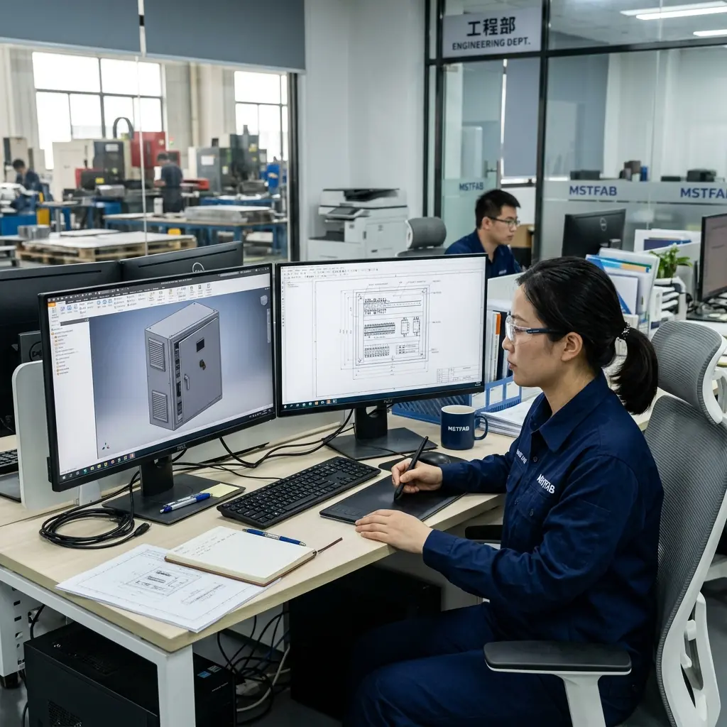
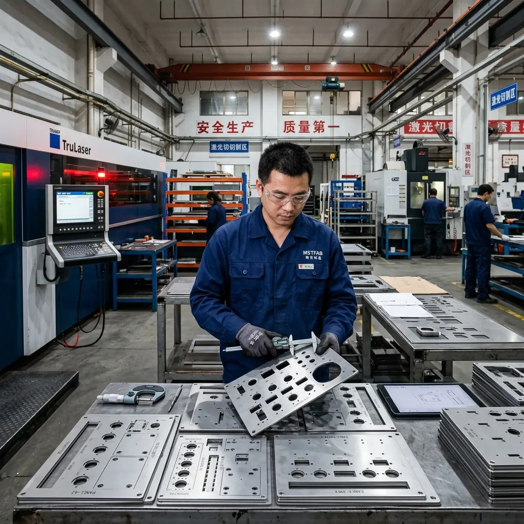


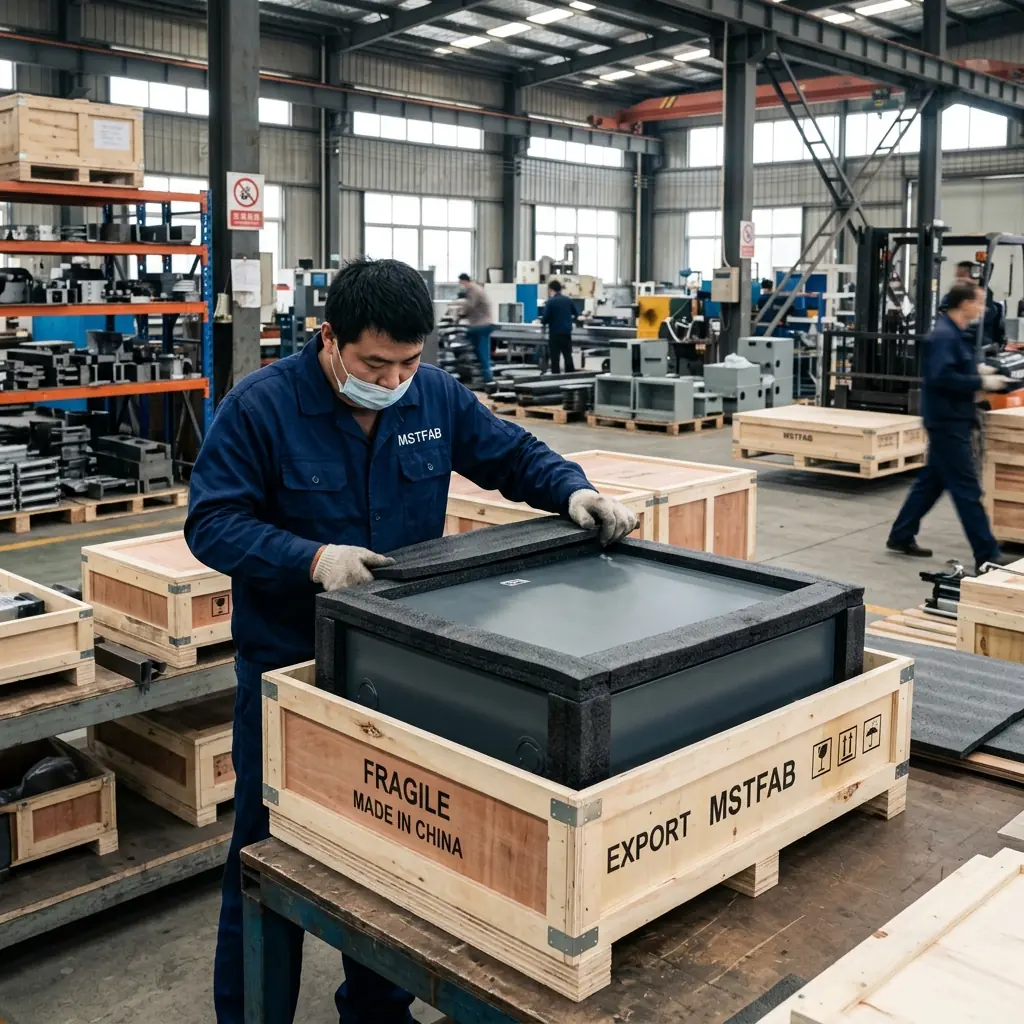
MSTFAB supports drawing-based electrical enclosure fabrication for OEM projects, including electrical cabinets, control boxes, HMI enclosures, PLC cabinets, mounting plates, doors, panels, cable-entry plates, ventilation panels, chassis sections, equipment housings, brackets, and multi-part mechanical assemblies.
The objective is straightforward:
Deliver electrical enclosure parts that fit the internal layout, support required hardware, remain practical to wire and service, and arrive ready for the buyer’s next assembly stage.
For broader fabrication capability, visit custom sheet metal fabrication for OEM parts.
Electrical Enclosures Are Mechanical Products With Electrical Consequences
The normal fabrication scope is the physical metal structure. This may include cabinet bodies, panels, doors, mounting plates, brackets, hardware, finish, inspection, packing, and mechanical assembly checks.
Electrical wiring, circuit design, PLC programming, software, electronic components, product-level testing, and final compliance certification should be separately defined by the buyer.
This project boundary is important. A metal enclosure can be mechanically complete while the buyer remains responsible for electrical schematics, component selection, wiring layout approval, thermal calculations, product safety, electrical compliance, IP or NEMA validation, functional testing, and final system approval.
The metal enclosure manufacturer helps ensure that the physical structure can support the required electrical layout.
What Is a Custom Electrical Enclosure?
A custom electrical enclosure is a drawing-based metal housing designed around the buyer’s equipment layout, mounting requirements, cable routing, access needs, material selection, surface finish, and intended environment.
It may include cabinet bodies, control boxes, doors and access covers, internal mounting plates, HMI panels, display openings, cable-entry plates, connector cutouts, ventilation panels, fan openings, filter frames, hinges, handles, locks and latches, grounding studs, PEM nuts and studs, rivet nuts, threaded inserts, internal brackets, hardware kits, and protective shipping materials.
Typical applications include PLC cabinets, machine control boxes, automation equipment enclosures, HMI enclosures, VFD cabinets, power distribution cabinet structures, telecom equipment enclosures, battery-system covers, EV charging cabinets, instrument housings, industrial control panels, network equipment cabinets, equipment access enclosures, and custom metal electrical boxes.
The enclosure should not only look correct when empty. It must work with the devices, wires, cable glands, mounting plates, fasteners, doors, service requirements, and final product assembly that come later.
Why Electrical Enclosures Require More Than Basic Cutting and Bending
An enclosure can be correctly cut and still fail later in assembly.
For example, a mounting plate may not fit after side panels are welded. A cable-entry opening may be too close to a bend. An HMI cutout may not match the real display frame. A door may bind after hinges and powder coating are added. A lock may not engage after the cabinet frame changes shape during welding. A grounding point may become covered by coating. A gasket surface may become uneven. A panel may flex around a large display opening. A finished cabinet may arrive scratched because packing was not designed around visible surfaces.
The useful question is not only: “Can you make this electrical enclosure?”
The better question is: “Can this enclosure be fabricated, wired around, opened, mounted, finished, inspected, packed, and repeated without creating extra work for the assembly team?”
Start With the Electrical Layout
An electrical enclosure should be designed around its internal components.
Before fabrication, the project package should clarify component mounting positions, DIN rail or mounting plate locations, cable-entry direction, cable gland locations, HMI or display positions, connector openings, ventilation requirements, fan and filter positions, door opening direction, lock and latch requirements, grounding points, service-access requirements, clearance for wiring and tools, required finish, and packaging requirements.
A cabinet body may look acceptable in CAD but still create problems if the mounting plate leaves no cable-routing space. A cable-entry plate may fit the external wall but interfere with internal components. A door may close properly as bare metal but lose clearance after hardware, gaskets, or coating are added.
The best enclosure design starts with the layout inside it.
DFM Review for Electrical Enclosures
DFM means Design for Manufacturing. For electrical enclosures, DFM review identifies practical risks before cutting, bending, welding, finishing, inspection, or packing begins.
A DFM review may consider material grade and thickness, overall cabinet dimensions, panel stiffness, hole and slot locations, hole-to-bend clearance, bend radius, tooling access, bend sequence, door-gap requirements, hinge locations, lock and latch cutouts, mounting plate clearance, cable-entry positions, ventilation locations, hardware installation sequence, grounding areas, gasket-contact surfaces, and packaging protection needs.
For example, a large HMI cutout may weaken a front panel and require a formed edge or reinforcement feature. A cable-entry opening may need more clearance around a bend or internal component. A PEM stud may need installation before powder coating. A grounding point may need masking to preserve metal-to-metal contact.
Materials for Electrical Enclosures
Material selection depends on environment, corrosion exposure, weight, visible appearance, finish route, stiffness, and buyer requirements.
- Carbon Steel: Indoor cabinets, machine control boxes. Verify thickness, welding, powder coating, and corrosion protection.
- Galvanized Steel: Internal panels, mounting plates. Verify surface condition, bends, and finishing compatibility.
- Stainless Steel: Wash-down cabinets, outdoor environments. Verify grade, weld cleanup, visible finish, and protective packing.
- Aluminum: Lightweight housings, electronics cabinets. Verify alloy, bend radius, stiffness, and anodizing or coating.
For material-specific content, see:
- Custom metal parts manufacturer for carbon steel
- Custom metal parts manufacturer for stainless steel
- Custom metal parts manufacturer for aluminum
- Custom metal parts manufacturer for galvanized steel
Laser Cutting for Electrical Enclosure Parts
Laser cutting creates the flat geometry for enclosure panels, cabinet doors, mounting plates, cable-entry plates, ventilation panels, brackets, and chassis components.
Typical laser-cut features include outer profiles, mounting holes, slots, HMI openings, display cutouts, push-button holes, connector cutouts, cable-entry openings, ventilation patterns, fan openings, filter-frame cutouts, hinge holes, lock cutouts, hardware insertion holes, grounding holes, alignment tabs, and bend reliefs.
The laser-cut layout should support the next manufacturing stage. A cable-entry opening needs sufficient clearance for actual connectors. Hardware holes must remain accessible after forming. A large display opening may need reinforcement for stiffness.
CNC Bending Creates Enclosure Geometry
CNC bending transforms flat sheet into cabinet bodies, doors, covers, channels, mounting supports, chassis sections, and reinforcement features.
A flat part can be correct before bending and still create problems after forming. Examples include a hole distorting near a bend line, a door becoming too narrow for its cabinet frame, a flange blocking screwdriver access, a mounting plate becoming difficult to install, a gasket-contact surface becoming uneven, a hinge moving out of alignment, or a cable-entry panel no longer aligning with the intended route.
Critical post-bend checks may include cabinet width, height, and depth, door gap, flange length, hinge location, lock location, mounting-hole alignment, panel flatness, squareness, hardware access, gasket-contact surface, and mounting plate clearance.
Welding and Structural Enclosure Assembly
Some electrical enclosures are assembled mainly through bends, removable panels, and hardware. Others require welding to create cabinet frames, bases, structural corners, reinforced sections, welded bodies, or equipment housings.
Welding adds strength. It also introduces heat. Heat can affect flatness, squareness, door gaps, hole positions, panel alignment, mounting plate fit, surface appearance, finish preparation, and final assembly condition.
Before welding begins, clarify weld locations, structural or cosmetic requirements, grinding requirements, fixtures, flatness requirements, and critical post-weld dimensions. A welded enclosure frame should not only be strong. It should remain square enough for doors, mounting plates, cable-entry panels, hardware, and electrical components to fit correctly.
Mounting Plates, Rails, and Internal Mechanical Layout
Electrical enclosures often need internal structures to support equipment installed by the buyer.
These may include mounting plates, DIN rail supports, terminal mounting panels, internal brackets, cable-support brackets, fan mounting plates, filter supports, grounding plates, equipment trays, internal chassis sections, and removable service panels.
The manufacturer should understand the mechanical relationship between enclosure body and internal parts. Before fabrication, confirm mounting-hole pattern, component spacing, cable-routing clearance, fastener direction, tool access, door opening clearance, ventilation path, grounding locations, service space, internal part sequence, and finish compatibility.
The enclosure should help the buyer wire and assemble more easily. It should not become a metal obstacle course.
Cable Entry, Ventilation, and Service Access
Cable-entry and ventilation features affect both the external and internal layout of the enclosure. Common requirements include bottom cable-entry plates, side cable-entry cutouts, rear cable openings, removable gland plates, connector openings, fan cutouts, ventilation louvers, filter frames, removable access panels, cable-routing brackets, and internal wire-duct support points.
Before fabrication, consider cable direction, connector dimensions, installation-tool clearance, gasket or sealing interface, internal wiring path, heat-generating component position, filter-service access, door opening space, wall-mount or floor-mount orientation, and surface-finish compatibility.
Cutting holes after coating is usually a poor production solution. The correct features should be planned before fabrication and finishing.
Doors, Hinges, Locks, Gaskets, and Grounding
An enclosure door is a mechanical system, not only a bent panel. It may require hinges, handles, locks, latches, gaskets, grounding straps, viewing windows, fasteners, HMI features, cable-entry features, service access, and finish allowance.
Before production, define door opening direction, hinge type and position, handle location, lock type, latch engagement, door gap, gasket-contact surface, grounding arrangement, fastener accessibility, and surface-finish allowance.
A door that looks aligned before finishing may still bind after coating, gasket compression, or hardware installation. Assembly verification should check actual opening, closing, locking, and access.
Surface Finishing for Electrical Enclosures
Surface finish affects corrosion resistance, visible appearance, grounding, thread function, door fit, gasket contact, handling, and packaging requirements.
Common finishing routes may include powder coating, wet painting, anodizing, zinc-related protective finishes, passivation, brushing, polishing, and protective film.
Before finishing, define finish type, color reference, texture, gloss level, visible faces, thread masking, grounding areas, gasket surfaces, door and panel gaps, and scratch-protection requirement.
Electrical Enclosures and IP or NEMA Requirements
The material alone does not create an IP-rated, weatherproof, or NEMA-rated enclosure. Final performance can depend on door and cover geometry, gasket design, latch pressure, cable-entry design, seam construction, ventilation features, drainage details, mounting orientation, hardware arrangement, final assembly method, and product-level validation and testing.
For projects requiring a specific IP or NEMA target, the buyer should provide the intended rating and relevant project requirements. The enclosure manufacturer can review mechanical fabrication requirements. Final system-level validation should remain defined and approved under the buyer’s project requirements.
Packaging for Electrical Enclosures
An enclosure can pass inspection and still arrive damaged if packing does not protect doors, visible surfaces, corners, hardware, and internal components.
This is especially important for powder-coated doors, brushed stainless steel panels, anodized aluminum covers, large cabinet bodies, hardware-installed structures, welded frames, HMI panels, and multi-part enclosure kits.
Packaging may include protective film, foam separation, edge guards, bubble protection, divider cartons, labeled hardware bags, part labels, reinforced cartons, pallets, wooden crates, moisture-control materials, and defined support points for larger structures.
A visible door should not rub against another panel in transit. A hardware bag should not move loose inside the cabinet body. A welded frame should be supported to reduce shifting or twisting during export handling.
How to Compare Electrical Enclosure Manufacturers
Do not compare suppliers only by cabinet size or unit price. Compare whether the supplier can control the complete mechanical enclosure route.
| What to Compare | What Buyers Should Confirm |
|---|---|
| Layout Review | Mounting plates, cable entries, ventilation, service access and component relationships |
| DFM Support | Bends, door gaps, hardware access, welding, finish compatibility and assembly risks |
| Laser Cutting | HMI cutouts, holes, vents, cable entries, lock openings and edge condition |
| CNC Bending | Cabinet geometry, flanges, door fit, flatness and squareness |
| Welding | Fixture planning, distortion control, cleanup and frame alignment |
| Hardware | Hinges, locks, latches, threads, grounding studs and hardware kits |
| Surface Finish | Coating, masking, grounding protection, visible-face quality and scratch protection |
| Inspection | Door movement, lock function, mounting plate fit, cable-entry alignment and final review |
| Packaging | Foam, film, labels, pallets, crates and support points |
| Repeat Orders | Revision control, approved process route and packing standards |
A low quote may cover only basic cutting and bending. Another quote may include DFM review, mounting plates, doors, hardware, welding, finishing, inspection, labels, export packing, and repeat-order control. Those are not the same delivery scope.
Frequently Asked Questions
What electrical enclosure parts can be custom manufactured?
Custom electrical enclosure projects can include cabinet bodies, control boxes, doors, covers, mounting plates, cable-entry panels, ventilation panels, HMI panels, chassis sections, brackets, grounding features, hardware-installed components, and multi-part assemblies.
Does electrical enclosure fabrication include wiring and electrical components?
The normal scope is physical sheet metal fabrication and mechanical assembly. Wiring, electrical components, circuit design, PLC programming, software, final electrical testing, and product-level compliance should be separately defined by the buyer.
Does a metal enclosure automatically meet an IP or NEMA rating?
No. Material alone does not establish an IP or NEMA rating. Seams, gaskets, doors, latches, cable entries, mounting orientation, ventilation, assembly method, and product-level validation all affect final performance.
Request Custom Electrical Enclosures
A reliable electrical enclosure manufacturer should do more than form sheet metal into a cabinet.
They should help ensure the enclosure fits the intended layout, supports required mounting points and hardware, allows practical cable routing and service access, protects visible surfaces, passes relevant inspection, and arrives ready for the next assembly stage.
Send your enclosure drawings, material requirements, quantity, internal layout, cable-entry details, hardware list, finish requirements, inspection needs, and packaging expectations through the MSTFAB quotation page.
Because a successful electrical enclosure does more than protect the components inside. It makes the entire product easier to wire, assemble, service, and reorder.
 WeChat Contact
 WhatsApp Me Directly