Floor-standing enclosure base DFM
A practical OEM guide to plinths, anchor patterns, bottom cable-entry clearance, welded base alignment and the installation evidence a buyer should request before volume production.

Quick Answer
An automation distribution enclosure plinth is not simply a steel rectangle beneath a cabinet. It is the interface where cabinet load, floor anchors, bottom cable entry, gland plates, removable covers and installation tools all compete for the same space.
Freeze the cabinet footprint, plinth height, functional datum, anchor pattern, fastener envelope, cable-entry keep-out, crossmember locations, leveling strategy and first-article evidence before metal is cut. A strong base rail directly across the incoming cable path is still the wrong base rail. It is merely wrong with excellent stiffness.
Freeze These Inputs Before Quotation
Keep the Supply Scope Boring and Clear
MSTFAB can manufacture
- Empty floor-standing enclosure bodies
- Welded base frames and plinths
- Anchor plates, tabs and slots
- Removable front and rear plinth covers
- Blank bottom cable-entry or gland plates
- Crossmembers, brackets and reinforcement
- Specified studs, hardware and powder coating
- Mechanical inspection and export packing
Buyer or panel builder owns
- Breakers, busbars, terminals and wiring
- Electrical protection and cable architecture
- Final populated mass and load cases
- Floor, skid and building anchors
- Leveling and installation strategy
- Protective-earth architecture
- Completed-panel testing and certification
- Site validation and commissioning
MSTFAB fabricates the released empty metal architecture. For the broader commercial enclosure scope, see our custom distribution enclosure fabrication page. The panel builder still decides what electrical system eventually lives inside.
Why the Bottom 100 mm Deserves a DFM Review
The conceptual load path is cabinet body to base frame to plinth to anchor interface to floor or skid. At the same time, incoming cables often need to pass through the same lower region. Support the cabinet and stay out of the cable path: two simple jobs that become suspicious of each other surprisingly quickly.
Model the installation surface
Include a simple floor, concrete pad, machine base or skid reference. It does not need architectural detail; it needs enough geometry to show where the cabinet sits, where anchors land and which access space survives installation.
Use a functional datum
Reference anchor centers from the cabinet or base-frame centerline, or another buyer-defined installation datum. The concrete anchor does not care how attractive the door gap is.
Separate two footprints
Cabinet outside dimensions and anchor centers are not the same specification. Define both. “Four anchors near the corners” is conversation; coordinates are manufacturing.
State the real load
The empty shell mass is not the final populated mass. If the base-frame design depends on completed-equipment loads, the OEM must supply the approved mechanical case rather than asking a sheet metal quotation to guess.
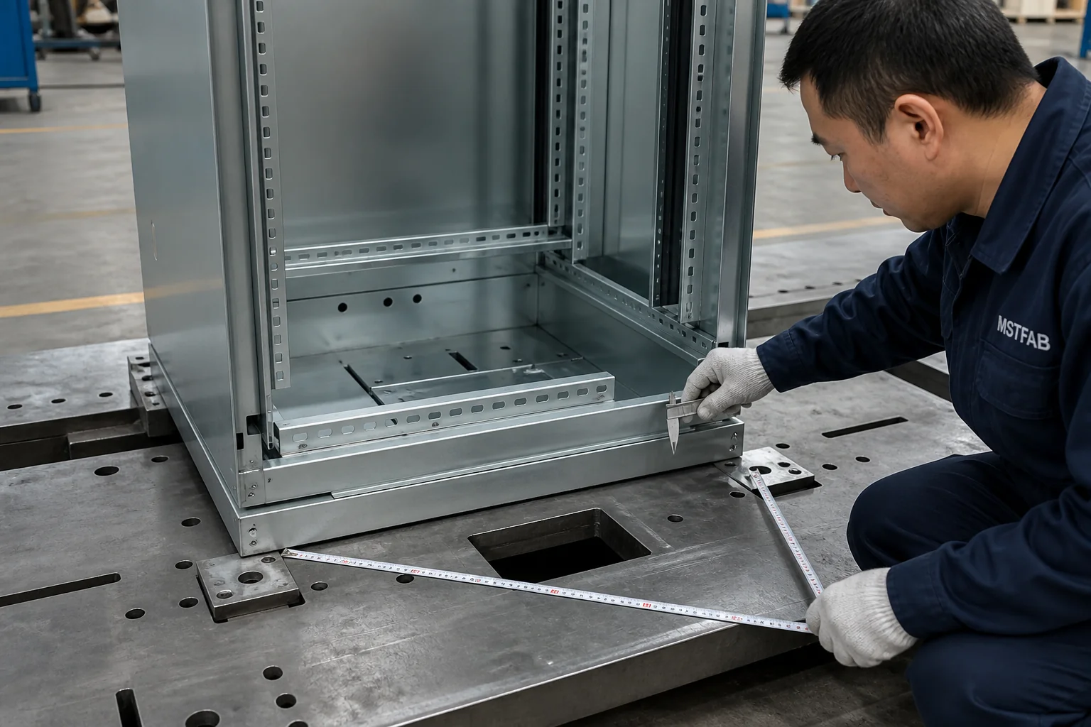
Anchor Holes, Slots and Installation Tools
Choose holes or slots deliberately
Round holes provide a defined position. Slots provide controlled adjustment. State slot direction, length, fastener size, washer envelope and allowed movement. Adjustment should be designed, not surrendered.
Match slot direction to variation
If expected site variation is mainly along one axis, orient the slot to manage that axis. Four random diagonal slots mostly help the drawing become abstract art.
Model the complete fastener
The bolt may fit while the washer, nut or socket does not. Provide enough mechanical information to protect head clearance and tool access even when MSTFAB does not select the building anchor.
Check access at floor level
The technician tightens anchors after the cabinet reaches the floor. Model the socket, ratchet or wrench against plinth returns, side panels, cable plates and rails in that real condition.
Plinth Height Should Solve a Real Problem
A taller plinth may improve cable turning, anchor access and removable-cover service. It also increases material, total cabinet height and packaging volume. A lower plinth can reduce cost but squeeze the exact interfaces commissioning needs.
Socket access, gland bodies, cable turns and cover removal become crowded.
Overall height, sheet use, shipping cube and visual proportions increase.
The value follows actual anchor, cable, service and project-envelope requirements.
“100 mm because we normally do” is family tradition. A DFM package should explain what must physically fit inside that 100 mm.
Bottom Cable Entry Is More Than an Opening
Freeze the bottom-entry zone before finalizing base rails and crossmembers. Review the buyer-defined gland or connector body, cable bend keep-out and installation tool, not only the nominal cutout. A 50 mm hole has never forced the attached hardware to remain 50 mm wide.
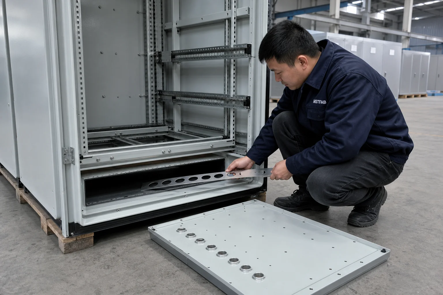
Overlay in one model
- Bottom opening and gland plate
- Anchor plates and bolt tools
- Front, rear and cross rails
- Buyer-defined cable turning envelope
- Plate fasteners and removal direction
- Plinth cover access
Detailed gland, conduit and connector cutout decisions belong on the dedicated automation enclosure cable-entry DFM page. This article controls the base volume that must preserve that route.
Removable Gland Plates Must Remain Removable
A bottom plate can leave upward into the cabinet, downward through the plinth or sideways through an access opening. Specify the path. Check its screws after anchoring and after plinth covers are installed. A plate trapped between welded rails is removable only in the philosophical sense.
Welded Base Alignment Controls the Cabinet Above
A welded rectangular base can pull into a rhombus, twist or bow. That can change anchor centers, cabinet verticality, door relationships and lineup alignment. Check overall width, depth, diagonals, rail spacing and critical mounting planes after welding, because the customer receives the assembly after heat has joined the discussion.
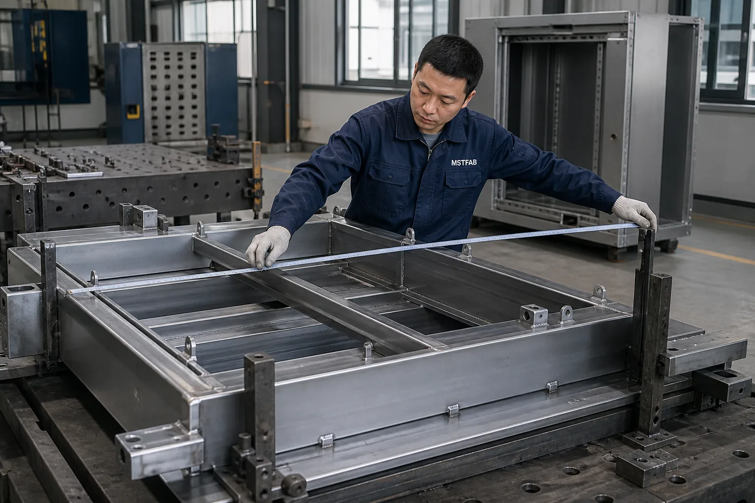
Fixture meaningful datums
Fixtures should control the base centerline, width, depth, rail spacing and anchor relationships that matter to installation, not an uncontrolled cosmetic edge.
Inspect after welding
Anchor tabs and crossmembers can move with tack sequence and weld pull. Measuring only laser-cut blanks proves the wrong stage.
Do not pull it flat onsite
Anchor bolts should anchor the cabinet, not provide structural therapy for a twisted base that may alter panel and door alignment.
Keep the load path approved
Moving a crossmember to clear cables may be sensible, but the buyer must still approve the resulting structural path and load case.
Leveling and Uneven Floors
Real floors are not always flat. The buyer may define leveling feet, shims, adjustable plates or another installation provision. If leveling points are specified, transfer their loads into appropriate structure and preserve wrench access with covers installed.
A threaded insert fitting into thin cosmetic sheet does not make that sheet an approved load path. Threads are convenient. They are not structural philosophy.
Plinth Covers Are Service Interfaces

Define whether front or rear covers provide access to anchors, cable entry or leveling points. Check their movement against the floor, cabinet doors, neighboring cabinets and skid structure. Captive fasteners can be useful when specified; nobody wants four tiny screws developing a permanent relationship with the space under a heavy cabinet.
Multi-Cabinet Lineups Need Shared Datums
For a row of distribution cabinets, control common plinth height, front datum, side relationship, anchor strategy and cabinet-coupling interfaces. Do not reference one cabinet from the front plinth face and the next from the rear body unless the project intentionally wants a staggered lineup.
A 2 mm height difference sounds modest on one cabinet. Across six doors it becomes an aesthetic feature nobody ordered.
Keep Handling Separate, but Model It Together
Fork pockets, lifting lugs and transport protection require their own approved handling review. They are not automatic plinth functions. However, the complete assembly model must still show fork pockets, anchor plates and cable entry together. A fork route directly under the bottom gland plate can make logistics happy and commissioning deeply unimpressed.
Grounding, Coating and Material Boundaries
Bolting a metal cabinet to a metal skid does not automatically define protective-earth architecture. MSTFAB can fabricate specified grounding studs, bonding points and masked contact areas; the panel builder owns conductor design, continuity criteria and electrical validation.
Powder coating can affect tight slots, threads and leveling hardware. Mask or protect only the drawing-defined functional interfaces. Galvanized, powder-coated carbon steel and stainless structures can all be valid project choices, but none can repair wrong anchor centers or a blocked cable path.
REACH Is Documentation Context, Not Plinth Geometry
EU substance obligations do not select plinth height, anchor spacing or crossmember position. Keep Candidate List, SCIP, coating declarations and BOM evidence on the dedicated REACH documentation for sheet metal enclosures page.
Do not use passivation color as legal evidence. As of August 2026, ECHA’s broader work concerning certain chromium(VI) substances remains a substance- and use-specific regulatory process, not a universal rule that a yellow surface has personally confessed to non-compliance. Verify the actual chemistry, supplier evidence and applicable law. See the ECHA restriction-intentions record.
Commercial plinth systems also illustrate why base geometry and cable access belong together; for example, Rittal describes base/plinth trim panels as supporting flexible cable entry. That is useful product context, not a universal dimension for custom fabrication. See the manufacturer reference.
Buyer Trust Matrix
A credible RFQ separates metal-factory evidence from site and electrical responsibilities. This table is less exciting than a certificate wall and much better at preventing surprises.
| Item | MSTFAB scope | Buyer / panel builder / site scope | Useful evidence |
|---|---|---|---|
| Cabinet shell | Fabricate released geometry | Define system architecture | Released STEP and PDF |
| Base frame and plinth | Fabricate and inspect | Define loads and installation | Post-weld dimensions |
| Anchor holes or slots | Manufacture pattern | Define anchors and datum | Pattern template fit |
| Bottom cable plate | Fabricate opening and plate | Define cable architecture | 3D keep-out check |
| Crossmembers | Fabricate to drawing | Approve load/cable relationship | Assembly overlay |
| Plinth covers | Fabricate and fit | Define service strategy | Removal demonstration |
| Grounding features | Fabricate mechanical points | Own PE design and test | OEM electrical validation |
| Finish | Apply specified process | Define environment and masks | Finished fit inspection |
| Mechanical FAI | Perform agreed checks | Define CTQs and acceptance | FAI report and photos |
| Final electrical system | Not supplied | Integrate and validate | Responsible project file |
Mechanical First Article: Test the Complete Base
For repeat programs, use a buyer-approved installation template representing anchor centers, cabinet footprint and cable opening. It answers the practical question: will this completed base fit the site pattern and preserve the entry route?
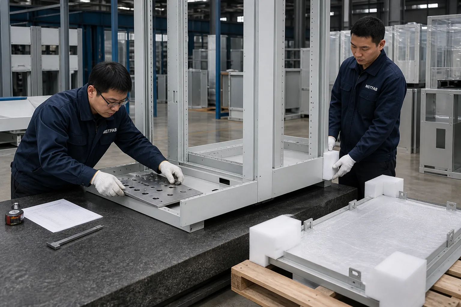
RFQ Checklist
CAD and mechanical inputs
- STEP/STP enclosure assembly
- Dimensioned PDF and revision
- Installed orientation and footprint
- Plinth and base-frame drawings
- Material, thickness and finish
- Buyer-defined load cases
- Floor or skid reference
- Leveling provisions
Installation and evidence
- Anchor centers and slot geometry
- Fastener, washer and tool envelope
- Bottom cable-entry keep-out
- Gland plate and removal path
- Crossmember locations
- CTQs and FAI requirements
- Prototype and production quantities
- Export packing requirements
Useful RFQ note: “MSTFAB shall fabricate the drawing-defined empty automation distribution enclosure shell, base frame, plinth, anchor interfaces, removable panels and bottom cable-entry metalwork only. Buyer owns the electrical system, site anchors, cable architecture, final mechanical loads and completed-equipment validation.”
Common Red Flags
Key Takeaways
Treat the plinth as a complete installation interface. Before fabrication, freeze:
- Cabinet footprint
- Plinth height
- Installation datum
- Anchor pattern
- Slot direction
- Fastener and tool envelope
- Crossmember positions
- Bottom cable entry
- Removable plate path
- Leveling provisions
- Lineup alignment
- Finished condition
- Mechanical FAI
- Revision control
The expensive version begins after the concrete anchors are drilled and the cables are waiting in the trench. The cabinet centers match. The anchor holes match. Then the electrician looks up and finds a welded crossmember across the cable opening. Every drawing was correct. The drawings simply had not been introduced.
Frequently Asked Questions
Can MSTFAB fabricate plinths for automation distribution enclosures?
Yes. MSTFAB can manufacture buyer-designed welded base frames, plinths, removable covers, anchor plates and bottom cable-entry panels as part of an empty enclosure shell.
Does MSTFAB manufacture the completed distribution board?
No. Breakers, busbars, wiring and finished electrical integration remain with the buyer or panel builder.
How tall should a plinth be?
There is no universal value. Height should follow the project’s anchor access, cable route, structural, service and overall-envelope requirements.
Should anchor holes be round or slotted?
Round holes provide defined positioning. Slots provide controlled adjustment when their direction, length and fastening method are intentionally specified.
Does MSTFAB select floor anchors?
Normally no. Anchor selection depends on substrate, loads and site requirements and remains with the responsible site or structural team.
Should the site anchor pattern appear in the STEP model?
Yes where possible. Showing the mating interface reduces the risk of designing the cabinet and foundation independently.
Can bottom cable entry interfere with the base frame?
Yes. Rails, crossmembers, anchor plates and cable-entry zones often compete for the same volume.
Can MSTFAB make removable gland plates?
Yes. Buyer-defined blank or cut plates, fastener interfaces and surrounding metalwork can be included in the empty-shell scope.
Can a plinth be used for forklift handling?
Only when specifically designed and approved for that function. Handling is a separate mechanical requirement, even when its geometry must coexist with the plinth.
Does galvanized steel determine base strength?
No. Strength depends on geometry, thickness, reinforcement, joining and approved loads, not simply a zinc coating.
Does REACH determine plinth thickness?
No. REACH addresses substance obligations; mechanical dimensions come from structural and fabrication requirements.
What should first article inspect?
Depending on the project: footprint, height, anchor pattern, slots, diagonals, squareness, cable opening, crossmember clearance, cover fit, tool access, coating and template fit.
What files should I send?
Send STEP/STP and dimensioned PDF drawings plus base details, anchor pattern, cable-entry geometry, material, finish, applicable loads, CTQs, quantities and inspection requirements.
What is the biggest plinth DFM mistake?
Designing the base before overlaying the anchor layout and bottom cable-entry plan. The plinth sits at the bottom, exactly where the floor and cables are waiting.
Send the Base, Anchor and Cable Layout Together
Upload STEP and dimensioned PDF files with the plinth, anchor pattern, bottom cable-entry keep-out, quantities and mechanical inspection requirements. MSTFAB will review the empty enclosure before quotation.
Editorial note: product and regulatory references define engineering boundaries only. Released drawings, buyer specifications and approved revisions remain the controlling manufacturing documents.
The broader automation distribution box shell checklist connects the plinth interface with PLC layout, cooling and service access.
 WeChat Contact
 WhatsApp Me Directly