
Release an outdoor electrical cabinet cooling-ready shell only after the airflow path, cooling-equipment interface, structural load path, filter service, gasket land, condensate route and validation owner are controlled.
A cooling unit can be correctly selected and still be poorly integrated. Air does not read arrows on a presentation slide, filters eventually collect dirt, doors carry real loads and water follows gravity. The drawing package must turn each assumption into geometry, access and evidence.
Assign the cooling decision before reviewing the metalwork.
The enclosure fabricator can identify missing cutouts, supports and access. It cannot responsibly invent the heat load, equipment capacity, contamination profile or system acceptance test.
Thermal owner
Releases heat load by state, ambient and solar inputs, internal limits, selected cooling method, operating margin and fault behavior.
Equipment owner
Controls the cooling-unit model, supplier drawing, mass, center of gravity, orientation, fasteners, power, cable, drain and service data.
Enclosure fabricator
Reviews drawing-defined cutouts, reinforcement, gasket lands, airflow geometry, access, manufacturability, inspection and packing.
Validation owner
Defines completed-system thermal, condensation, ingress, electrical, environmental and compliance validation and acceptance evidence.
Review how the cooling path can stop working.
A useful DFM review asks what changes after assembly, transport, filter loading, door movement and field service. That is where tidy CAD models meet less tidy reality.
| Failure mode | Why it happens | Release control | Evidence |
|---|---|---|---|
| Airflow short circuit | Supply air returns to the exhaust before reaching hot components, or the mounting plate blocks the intended path. | Control intake, exhaust, baffles, clearances, cable zones, pressure intent and the installed component envelope. | Released airflow drawing, open-path inspection and configured-system thermal validation. |
| Intake restriction | Filters, guards, rain features, ducts and contamination add resistance that a free-air fan value does not represent. | Use supplier data and buyer-defined loaded-filter assumptions; provide replacement access and service clearance. | Correct fan and filter identity, aperture inspection, access check and the responsible maintenance plan. |
| External recirculation | Hot discharge air can return to the intake because of spacing, orientation, nearby walls or a poorly separated interface. | Release external clearance, intake and discharge zones, barriers and installation constraints. | Equipment interface drawing, site installation requirements and completed configuration review. |
| Mounting-panel distortion | Cooling-unit mass and service loads can change panel flatness, door alignment, hinge reactions and gasket compression. | Control mass, center of gravity, support path, reinforcement, fasteners, opening state and replacement handling. | Dimensional results, fit check, door or panel operation and evidence tied to the approved equipment revision. |
| Water or condensate trap | Drain routes lack fall, terminate poorly, cross sensitive zones or become blocked during assembly or field installation. | Define collection points, channels, openings, hoses, termination, protection and access for inspection or cleaning. | Drain-path inspection and buyer-owned completed-system condensation and environmental validation. |
| Seal interruption | Cutouts, fasteners, cable entries, uneven mounting planes or drain penetrations interrupt the intended enclosure boundary. | Release the gasket land, surface condition, fastener pattern, penetrations, closures and installation controls. | Dimensional and visual inspection plus the responsible completed-assembly ingress test where required. |
Control the path, not just the opening area.
Louvers, rain hoods, guards and filters affect both airflow and environmental exposure. Their locations must work with the internal equipment layout and the site’s service plan.
Intake location
Keep the released opening clear of the finished equipment envelope, cable congestion, splash paths and service obstructions.
Exhaust location
Separate hot discharge from the intake and show external clearances that the site installation must preserve.
Filter service
Define the selected filter, removal direction, access state, retainers and the tools or fasteners required for replacement.
Rain and debris
Control hood, louver, screen, drain and guard geometry without claiming performance beyond the approved verification plan.
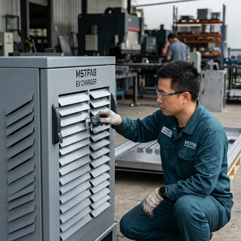
Keep airflow and service routes open after assembly.
Mounting plate
Release: depth, standoffs, edge gaps, openings and permitted component zones.
Check: whether the plate blocks intake, exhaust or cooling-unit return paths.
Components
Release: configured equipment envelopes, hot zones, wire ducts and keep-out areas.
Check: the actual arrangement, not an empty cabinet with beautifully unobstructed air.
Cables
Release: bend space, entry points, support, separation and service loops.
Check: that installed cable bundles cannot close a designed flow gap or block a filter.
Maintenance
Release: door states, panel removal, filter access, tools, lifting and replacement envelopes.
Check: that routine service does not require disturbing unrelated wiring or seals.
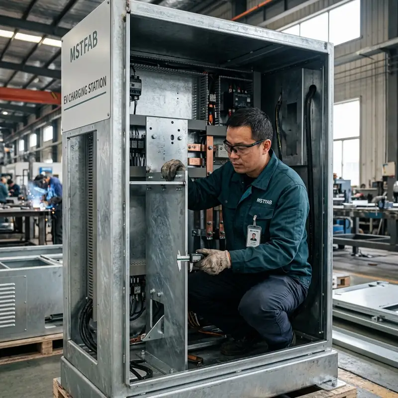
Treat cooling hardware as a real mechanical load.
A cutout removes panel stiffness while the cooling unit adds mass, fastener reactions and service loads. Door-mounted equipment also changes hinge, latch and gasket behavior through the opening cycle.
Cooling equipment installed, door or panel latched, gasket compressed and normal vibration or fan loads present.
Equipment mass acts through hinges and stops while cables, hoses and drains move through their allowed range.
Fasteners removed, temporary support or lifting used and the mounting plane protected from uncontrolled loading.
Cooling equipment installed or removed according to the approved packing and restraint method.
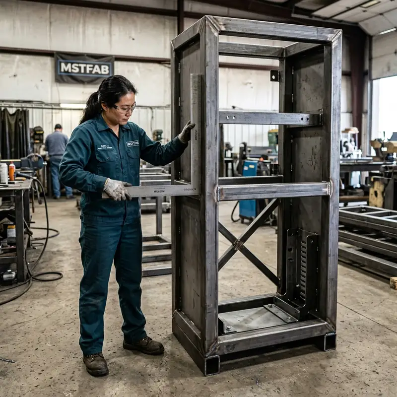
Release where water starts, travels and leaves.
A drain drawn nowhere tends to drain nowhere. The system owner should define condensate behavior, while the enclosure drawing controls the trays, channels, openings and protected routes included in the metalwork.
Source
Identify cooling-unit drains, cold surfaces, pressure changes, humidity conditions and any other expected collection point.
Route
Show fall direction, channels, hoses, clips, penetrations and separation from electrical or corrosion-sensitive zones.
Termination
Define where the drain exits, how the field connection is made and how splash, insects, blockage or freezing are addressed.
Inspection
Make critical paths visible or testable and name the responsible completed-system condensation validation.
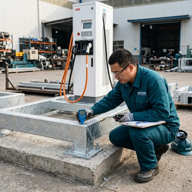
Close the loop from risk to inspection.
The inspection plan should identify which evidence belongs to the fabricator and which belongs to the configured system. A dimension report cannot replace a thermal test, and a thermal image cannot prove an uncontrolled drawing revision.
Send the cooling risks with the cabinet files.
Provide a STEP or STP assembly, controlled 2D PDF drawings and buyer-controlled DXF or DWG flat-pattern information when applicable. Include the cooling-equipment supplier drawing and the inputs needed to review each failure mode.
- Equipment heat load by operating state
- Ambient, solar and contamination profile
- Selected cooling method and equipment model
- Configured component and cable envelopes
- Intake, exhaust and return paths
- Filter and fan service requirements
- Mass, center of gravity and orientation
- Cutouts, fasteners and gasket lands
- Condensate route and field termination
- Inspection and validation ownership
MSTFAB does not publish one MOQ, lead time or tolerance for every project. Feasible commercial and manufacturing terms are confirmed from the released scope and quotation.
Outdoor electrical cabinet cooling FAQ
Who owns the cooling selection and sizing for an outdoor electrical cabinet?
The buyer, OEM or responsible thermal engineer owns the cooling selection and sizing from the released equipment heat load, environmental profile, temperature limits, duty cycle, power, maintenance and compliance requirements. MSTFAB fabricates the approved mechanical interfaces and empty enclosure shell from the released drawing package.
Do louvers or a rain hood prove an enclosure rating?
No. They are mechanical features whose geometry can be inspected, but any claimed rating depends on the applicable standard, complete assembly, installed equipment, openings, filters, gaskets, drainage, installation and verification plan. The release package should name the responsible test and acceptance party.
What should be controlled for a filter-fan cooling path?
Control the selected fan and filter, airflow direction, intake and exhaust locations, pressure intent, guards, rain management, internal obstructions, service clearance, filter replacement method and the acceptable condition as the filter loads. The responsible thermal team defines the required flow and maintenance assumptions.
Can a cooling unit be mounted on an enclosure door?
It can be considered when the approved design controls mass, center of gravity, door and frame stiffness, hinge and latch reactions, gasket compression, cable and drain routes, opening stops, handling and replacement states. Suitability must be verified for the actual equipment and enclosure geometry.
Who owns condensation control in the completed cabinet?
The buyer, OEM or responsible system engineer owns the thermal and humidity model, cooling-unit behavior, condensate collection, drain termination, freeze and blockage risks and completed-system validation. MSTFAB can fabricate drawing-defined trays, channels, drain openings and protected routes included in the approved scope.
Does MSTFAB publish one MOQ, lead time or tolerance for every cooling-ready cabinet?
No. Cabinet size, material, cooling interface, reinforcement, hardware, sealing details, finishing route, inspection, quantity and packing affect the project. Feasible tolerances, quantity and schedule are confirmed from the released drawings and quotation.
Release the cooling path as controlled metalwork.
Send the thermal inputs, cooling-equipment data, cabinet model, airflow geometry, load paths, drainage details, service states and required evidence. MSTFAB will review the drawing-defined sheet metal scope and return project-specific questions for quotation.
 WeChat Contact
 WhatsApp Me Directly