
Release a passive thermal enclosure shell only after the environmental assumptions, solar exposure, wall and roof architecture, insulation specification, thermal bridges, penetrations, condensation paths, service states and validation owner are controlled.
A double wall is not automatically a thermal design, and insulation is not a magic blanket. If the drawing does not define the cavity, material, retention and interfaces, the quotation is mostly guessing in a tidy spreadsheet.
Give each thermal decision one clear owner.
Heat load, airflow, heavy cooling hardware and passive shell construction influence one cabinet, but they should not compete inside one article or one vague purchase specification.
Thermal inputs
Use the heat-load input checklist for equipment states, ambient conditions, solar assumptions, limits and cooling-selection ownership.
Airflow geometry
Use the airflow-path and ventilation release guide for openings, pressure zones, filters, louvers, baffles and fan interfaces.
Heavy component loads
Use the HVAC mounting load-path checklist for mass, center of gravity, reinforcement, hinges, latches and service loads.
Passive shell features
This page owns the fabrication release for sun shields, double-wall panels, insulation cavities, thermal breaks, penetrations and drainage interfaces.
Start with inputs, not a favorite panel detail.
A cavity width or foam name copied from another project is not an engineering basis. The released package needs controlled environmental assumptions and a responsible owner for materials, interfaces and system validation.
OEM or thermal owner
Defines ambient and solar inputs, equipment heat load, internal limits, thermal architecture, condensation strategy and completed-system acceptance.
Material or compliance owner
Controls insulation, adhesive and isolation materials, including temperature, moisture, fire, smoke, chemical and regulatory requirements.
Shell fabricator
Reviews manufacturability and produces the released skins, liners, cavities, shields, spacers, retainers, gasket lands and drain features with agreed evidence.
Integrator or test party
Installs equipment and utilities, closes the defined interfaces, and verifies structural, thermal, condensation, ingress, environmental and compliance performance.

Turn thermal concepts into inspectable geometry.
The fabricator can measure gaps, cavities, locations and retained materials. The responsible thermal team must decide what those features need to achieve in the completed configuration.
| Feature | Buyer-controlled input | Fabrication or FAI evidence |
|---|---|---|
| Environmental basis | Ambient and humidity profiles, solar exposure, orientation, altitude when relevant, contamination, duty cycle and internal limits. | Recorded design-input reference and drawing revision used for the released shell features. |
| Sun shield or outer skin | Covered faces, projected area, air-gap intent, wind and handling inputs, attachment concept, drainage and service access. | Shield geometry, gap, support and fastener position, edge condition, drain path and finished assembly fit. |
| Double-wall cavity | Inner and outer skin materials, cavity depth, seams, access, keep-outs and allowable conductive connections. | Skin and liner geometry, cavity dimensions, spacer and retainer location, joints and finished access. |
| Insulation package | Material, thickness, density, temperature and moisture behavior, fire and smoke requirements, retention, joints and prohibited substances. | Material identity when included, placement, coverage, joints, compression, retention and photographs before closure. |
| Thermal bridges | Accepted and restricted conductive paths through frames, brackets, fasteners, hinges, rails and penetrations. | Controlled spacer, isolator, bracket, fastener and keep-out geometry in the released configuration. |
| Penetrations and closures | Cable, cooling, drain and mounting penetrations; gasket interfaces; closure states; and system-level verification ownership. | Cutout and hole positions, gasket-land condition, covers, drain features and agreed fit or operation checks. |
Useful rule: if a passive feature matters to thermal performance, give it a datum, a finished condition and an evidence owner. Otherwise it is a hope wearing a part number.
Control the air gap, supports and escape paths.
An outer skin can intercept solar exposure, but its supports, openings and service clearances become part of the real assembly. The drawing should show how water, air, tools and replacement parts move around it.
Sun shield or canopy
Define the covered faces, gap, stand-offs, attachment method, wind and handling inputs, lower and upper openings, edge details, drain path and removal sequence.
- Keep shield supports clear of required service access.
- Show where trapped water can leave.
- Coordinate fasteners with internal equipment and liners.
- Protect the feature during packing and lifting.
Double-wall panel
Define inner and outer skins, cavity boundaries, spacer locations, seams, access panels, penetrations and any conductive path that crosses the intended thermal boundary.
- Control cavity depth in the finished assembly.
- Reserve space for insulation joints and retention.
- Coordinate hinges, latches, rails and cable entries.
- Decide whether the liner is removable or permanently closed.
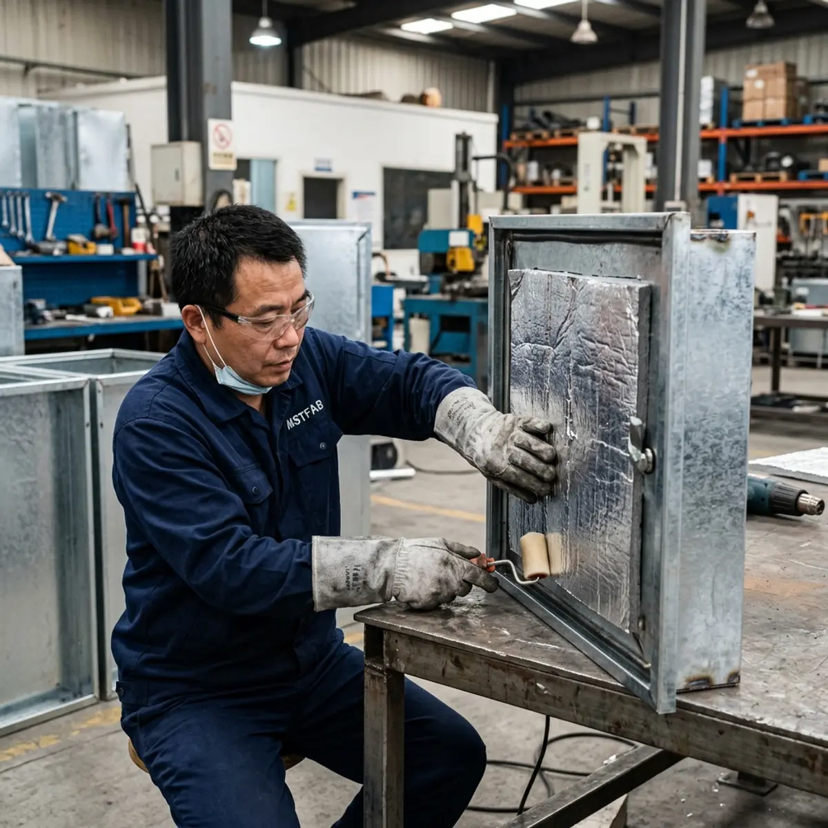
Specify what fills the cavity and what crosses it.
Insulation performance depends on the selected material and installed condition, while frames, brackets, fasteners and penetrations can create conductive paths around it. Both need controlled inputs.
Material identity
Control the material, thickness, density, temperature and moisture behavior, fire and smoke requirements and any prohibited substances.
Retention method
Define adhesive, clips, retainers or a removable arrangement, including surface preparation and compatibility requirements owned by the buyer.
Joints and compression
Show butt joints, overlaps, corners, cutouts and acceptable compression rather than leaving field crews to invent the pattern.
Conductive paths
Identify brackets, rails, fasteners, hinges and frames that cross the cavity so the responsible engineer can approve, isolate or relocate them.
Review every break in the thermal boundary.
A cable entry, mounting rail, drain, hinge or cooling cutout can affect several systems at once. Coordinate the mechanical feature without pretending the shell drawing alone proves completed performance.
Defined orientation, shield position, surface condition, clearances and equipment state used by the responsible thermal model.
Condensation assumptions, drainage, retained moisture risks, material compatibility and controls owned by the responsible team.
Removed panels, displaced insulation, flexible seals, tool access and the method used to restore the released configuration.
Temporary protection, water paths, loose liners or shields, packing restraints and any materials installed after delivery.

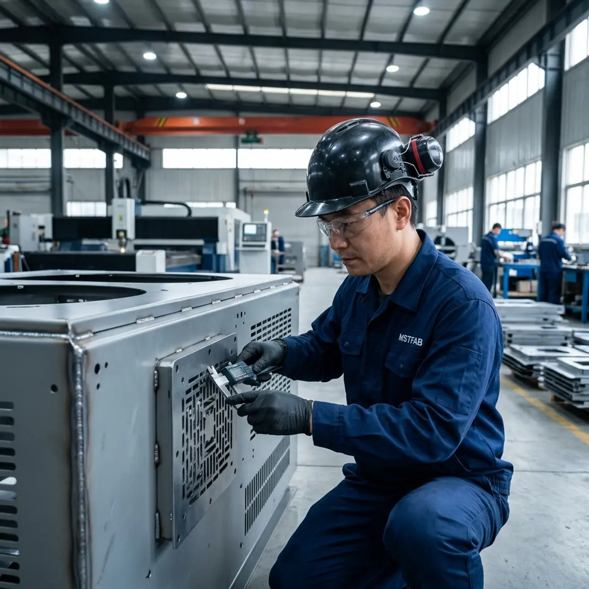
Record the hidden work before closing the cavity.
Once the liner is installed, a neat exterior cannot show insulation coverage, retained joints or concealed spacers. Agree on evidence while those features are still visible.
Input review
Record the environmental basis, architecture revision, material requirements, interfaces and open technical questions.
Open-cavity checks
Verify spacers, retainers, insulation identity and placement, joints, penetrations and concealed drainage before closure.
Finished FAI
Measure shield gaps, panel and liner geometry, critical openings, gasket lands, drains and service-panel operation.
Release record
Connect results, photographs, deviations and approvals to the part number, drawing revision and first-article identity.
For measurement planning and report structure, use the dimensional inspection report guide.
Send the thermal architecture with the cabinet files.
Provide a STEP or STP assembly, a controlled 2D PDF, and DXF or DWG data when buyer controlled. Identify system requirements, fabrication CTQs and validation responsibilities separately.
- Ambient, humidity and solar assumptions
- Cabinet orientation and equipment states
- Outer skin, liner and cavity geometry
- Sun-shield gaps, supports and drainage
- Insulation specification and retention
- Thermal bridges and penetrations
- Service, replacement and transport states
- Quantity, CTQs and required FAI evidence
MSTFAB does not publish one MOQ, lead time or tolerance for every passive thermal enclosure. Geometry, material, wall architecture, insulation scope, welding, hardware, sealing details, finishing route, inspection, quantity and packing shape the quotation. Selected finishing processes may be completed by qualified long-term partners and are identified through the approved project scope.
Passive thermal enclosure shell FAQ
What belongs in a passive thermal enclosure shell release package?
Include the environmental and solar assumptions, cabinet orientation, outer-skin and inner-liner geometry, sun-shield gaps and supports, insulation material and cavity requirements, thermal-bridge decisions, penetrations, gasket and drainage interfaces, service states, fabrication CTQs and the responsible validation plan.
Who specifies the insulation used inside a double-wall enclosure?
The buyer, OEM or responsible thermal and compliance team should control the insulation type, thickness, density, temperature limits, moisture behavior, fire and smoke requirements, adhesive or retention method, prohibited substances and acceptance criteria. MSTFAB can fabricate the released cavity and retention features and place buyer-specified insulation when included in the approved scope.
Does a sun shield or double-wall shell remove the need for active cooling?
Not automatically. Passive shell features can change solar gain and heat transfer, but the responsible thermal designer must evaluate the actual equipment heat load, ambient conditions, orientation, duty cycle and internal limits before selecting the cooling architecture.
How should thermal bridges be handled in the enclosure drawing?
Identify fasteners, brackets, frames, hinges, mounting rails, cable entries and other conductive paths that cross the thermal boundary. The responsible engineer should define which paths are acceptable and which require spacing, isolation, relocation or other controlled geometry. The drawing should show the resulting fabrication features and inspection points.
Do continuous gasket and drain features prove an IP or NEMA rating?
No. These are inspectable mechanical interfaces, but any rating depends on the applicable standard, complete assembly, installed components, penetrations, closures, drainage configuration and verification plan. The released package should identify the responsible test and acceptance party.
Does MSTFAB publish one MOQ, lead time or tolerance for every passive thermal enclosure?
No. Cabinet size, material, wall architecture, insulation scope, welding, hardware, sealing details, finishing route, inspection, quantity and packing affect the project. Feasible tolerances, quantity and schedule are confirmed from the released drawings and quotation.
Release the passive shell features as controlled interfaces.
Send the environmental inputs, thermal architecture, cabinet assembly, insulation specification, shield and cavity details, service states and required evidence. MSTFAB will review the drawing-defined sheet metal scope and return project-specific questions for quotation.
 WeChat Contact
 WhatsApp Me Directly