
Release a heavy enclosure HVAC mount only after the component identity, mass, center of gravity, orientation, operating and service loads, reinforcement path, closure hardware, gasket land, drainage, cable movement and validation owner are controlled.
A cutout can match perfectly while the surrounding panel still behaves badly. The component does not stop being heavy because the holes line up, and the hinge should not become the unpaid structural engineer.
Keep thermal selection, shell design and structural release separate.
These subjects meet at the same cabinet, but each needs a different owner and evidence package. Separating them makes the drawing easier to quote and keeps a useful engineering page from becoming a keyword cupboard.
Thermal inputs
Use the heat-load input checklist for equipment states, ambient conditions, solar exposure, limits and cooling-selection ownership.
General shell design
Use the climate-controlled enclosure design guide for double-wall construction, sun shields, material choices and overall weather-exposure planning.
Telecom interface detail
Use the telecom cooling-hardware interface checklist for application-specific cutouts, seals, drains, connectors and service envelopes.
Structural load path
This page owns how a buyer-specified HVAC or heat-exchanger load moves from the component mount through the panel, reinforcement, frame, closures and installation supports.
Freeze the inputs before choosing the rib.
A thicker panel or larger stiffener is not a complete engineering decision. The released package needs the real component, real orientation, real service state and a named owner for the structural assumptions.
OEM or mechanical owner
Approves the component, load cases, allowable movement, mounting location, attachment to the site structure and completed-system acceptance criteria.
Component owner
Provides the controlled model or drawing, mass, center of gravity, mounting and service instructions, fasteners, gasket, drain, cable and relevant dynamic inputs.
Shell fabricator
Reviews manufacturability and builds the released panel, cutout, reinforcement, frame, bracket, hinge and latch interfaces with the agreed inspection evidence.
Integrator or test party
Installs the component and utilities, controls field attachments, and verifies structural, thermal, ingress, environmental and compliance performance.
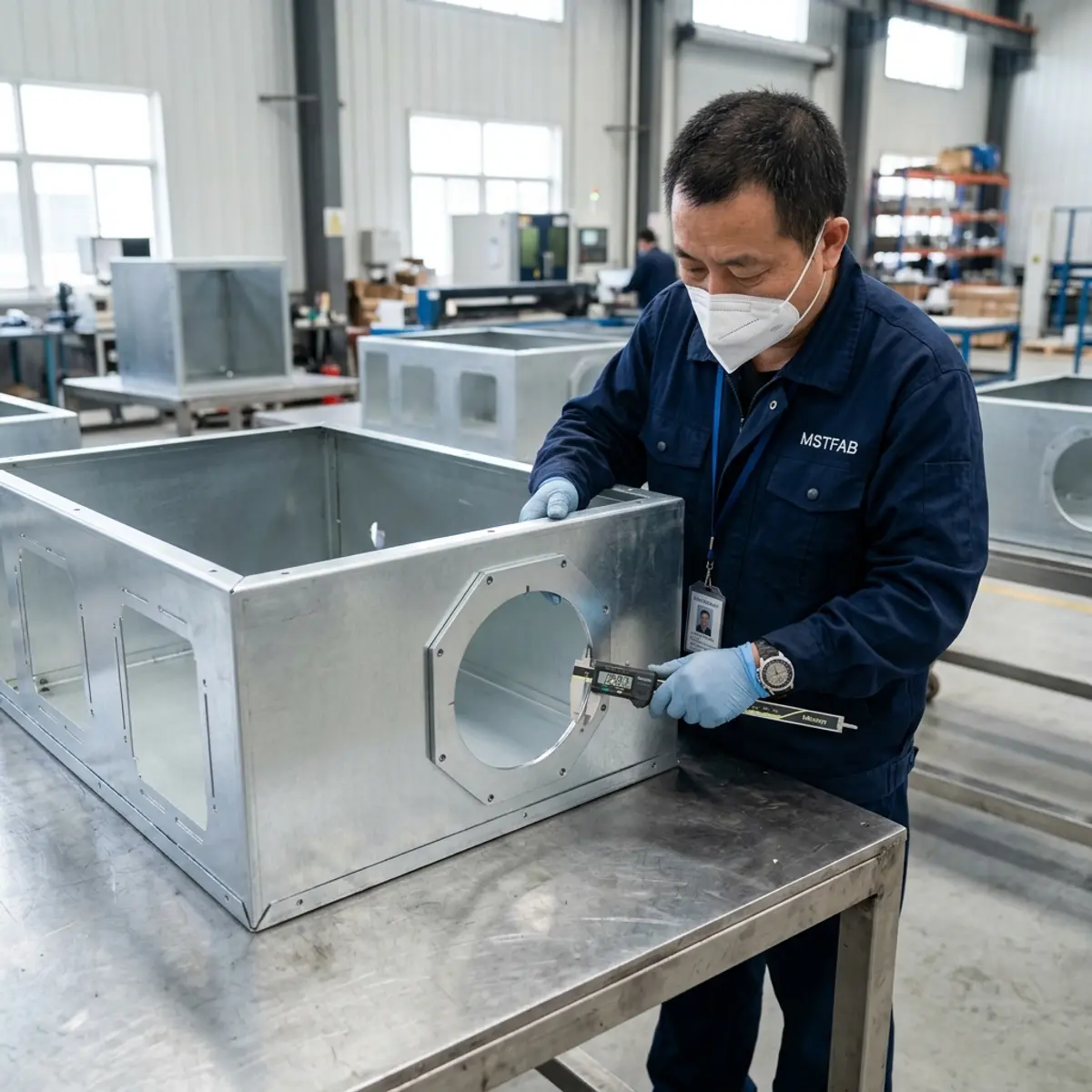
Follow the load past the mounting holes.
The structural path begins at the cooling component and ends at the cabinet’s installation support. If the drawing stops at the cutout, the most important interfaces are still hiding off-page.
| Interface | Buyer-controlled input | Fabrication or FAI evidence |
|---|---|---|
| Component identity | Manufacturer, model, revision, approved substitute rule, orientation and controlled drawing or sample status. | Recorded reference used for DFM, the released drawing and any trial fit. |
| Mass and center of gravity | Installed mass, center-of-gravity coordinates, service-removal state and accessories that remain attached. | Mounting position, interface geometry and traceable review against the approved inputs. |
| Load cases | Static orientation, door-open condition, transport restraints, handling, site loads and vibration or shock inputs when applicable. | Released reinforcement and joint arrangement, plus the evidence level named by the responsible engineer. |
| Panel and reinforcement | Allowable deflection, keep-out areas, weld restrictions, coating faces and component gasket requirements. | Panel flatness or profile, rib and bracket position, joint condition and finished mounting-plane checks. |
| Closure or fixed support | Door swing, hinge and latch concept, frame interface, fixed-panel attachment and service frequency. | Door alignment, latch engagement, frame fit, fastener access and operation in the defined state. |
| Cabinet to site | Base, plinth, wall or pole attachment, anchor pattern, lifting state and installation responsibility. | Mounting-feature position, base or frame geometry, lifting-feature records and packing restraints when specified. |
Useful question: if the component moves with a door, is opened for service or is removed, which parts carry it in that state? Ask this before coating, when the answer is still inexpensive.
Door-mounted and fixed-panel units create different problems.
Neither arrangement is automatically correct. The released choice should reflect access, cable and drain movement, frame stiffness, service sequence and the responsible validation plan.
Door-mounted component
The cooling unit moves with the closure. Review the combined center of gravity, hinge and latch interfaces, stop or stay, cable and drain flex, opening force, service position, gasket compression and frame distortion.
- Define the open and closed load states.
- Keep fasteners and lifting points accessible.
- Control cable and drain bend paths through the swing.
- Check alignment after the finished component is installed.
Fixed-panel component
The component stays with the frame or sidewall. Review local panel support, frame transfer, site clearance, external protection, service removal, adjacent doors and how the cabinet reaches its base or wall attachment.
- Define the support path into the frame.
- Reserve the removal and tool envelope.
- Protect connectors, drains and protruding hardware.
- Check access after nearby equipment is installed.
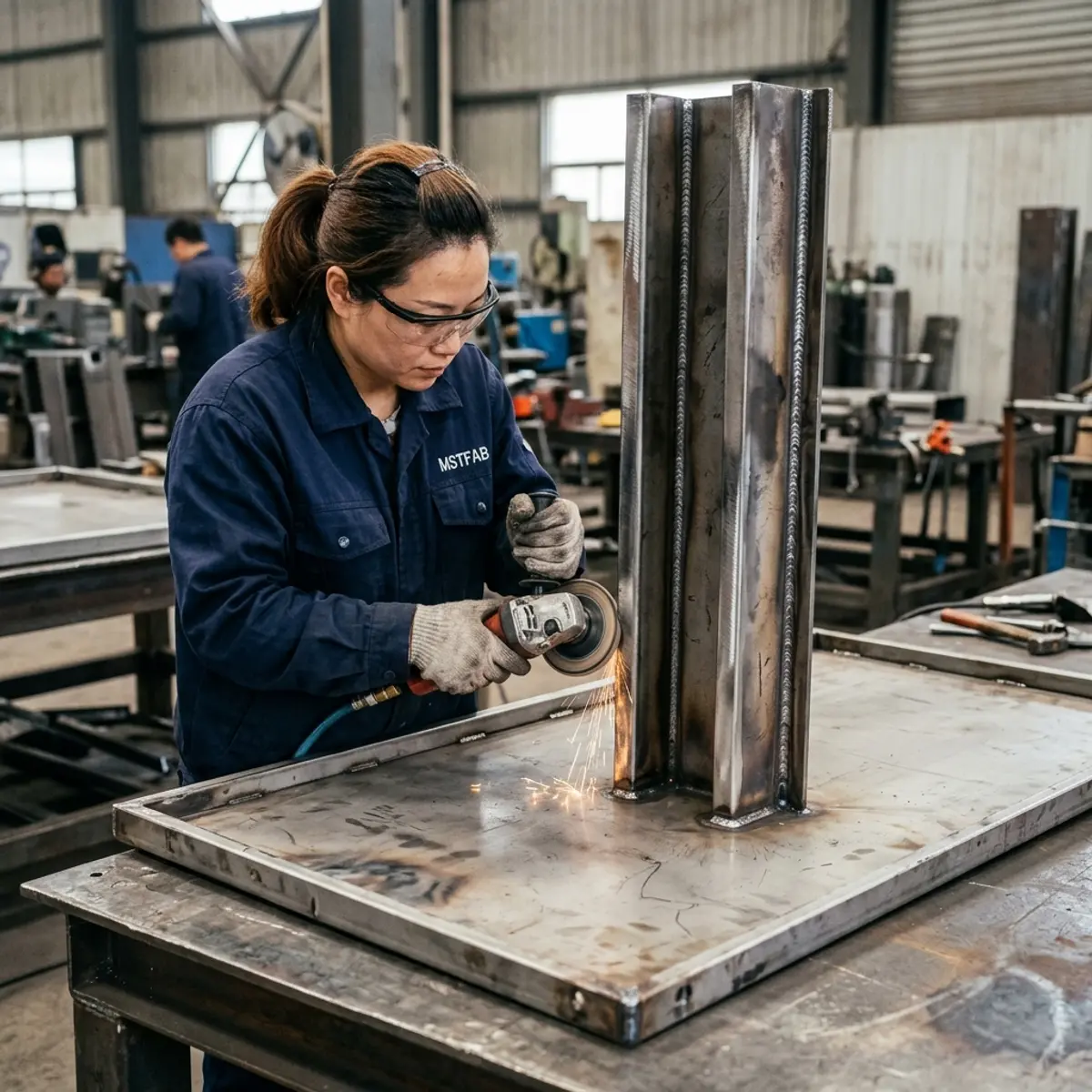
Flatness is part of the interface, not a beauty contest.
Cooling-component gaskets need a continuous mating condition. Welding sequence, cutout corners, fastener spacing, reinforcement joints, panel forming and finishing can change that condition after the first clean measurement.
Controlled datum
Identify where cutout position, holes, reinforcement and component location are measured from in the finished assembly.
Finished condition
State whether flatness, profile, hole fit and trial assembly are checked before finishing, after finishing or both.
Gasket land
Define the required contact area, joints, penetrations, edge condition and features that must remain clear of the seal.
Fastener access
Confirm installation direction, tool clearance, captive hardware, backing features and the sequence used to compress the interface.
Review more than the cabinet standing quietly.
The awkward loads often appear during delivery, opening or maintenance. Put those states on the release package so the shell is not designed around a single showroom pose.
Component installed, closures latched, utilities connected and the cabinet attached as intended at the site.
Closure hardware, stops, temporary supports, flexible connections and technician access in the service position.
Removal direction, lifting method, temporary support, fastener access and protection of the gasket land and finish.
Cabinet restraints, component shipping status, lifting points, vibration assumptions and any temporary braces or separate packing.
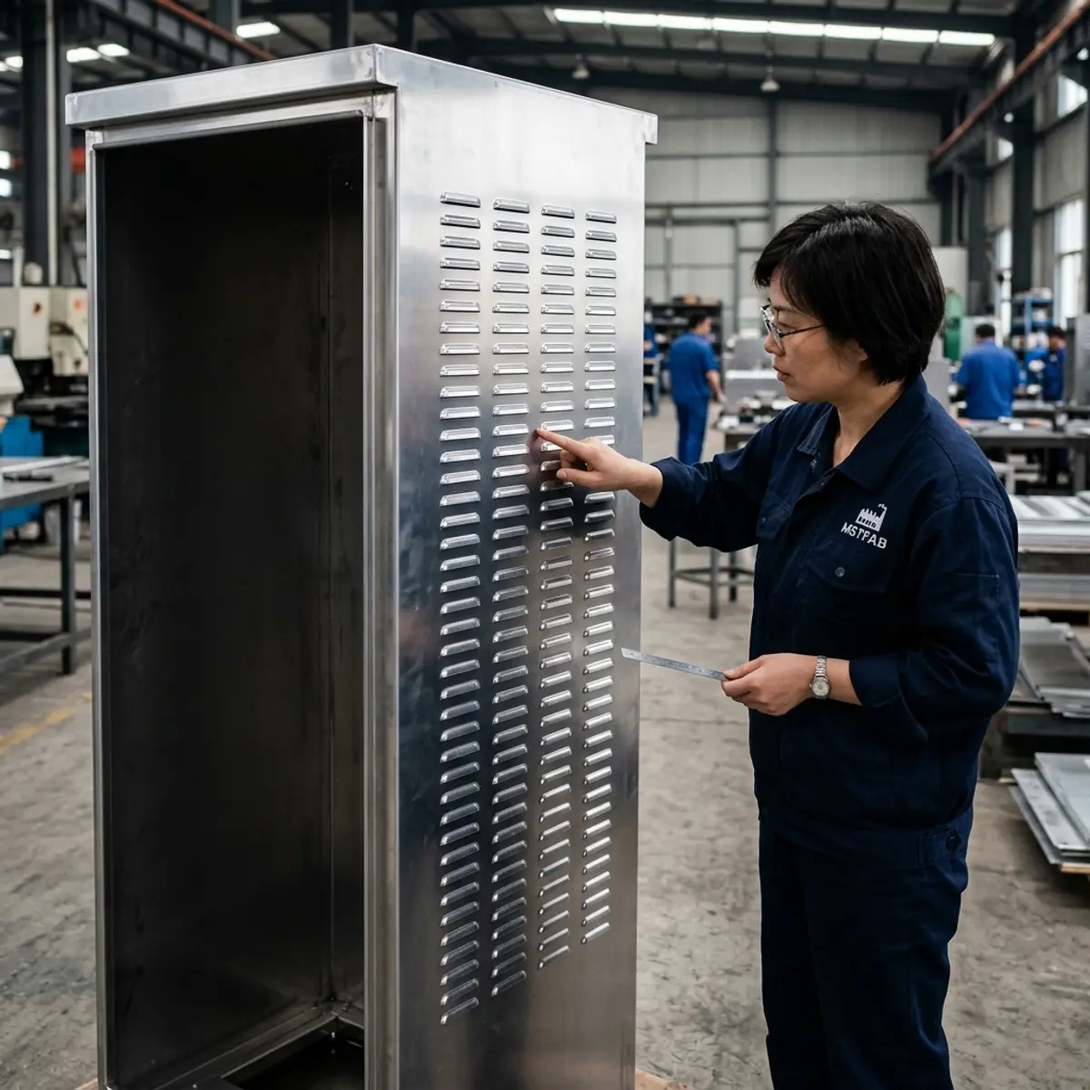

Ask for evidence tied to the drawing revision.
A photograph of a cabinet is not a structural release record. Agree on the evidence that confirms the manufactured interfaces and separates measured facts from system-level engineering approval.
Input review
Record the component revision, orientation, load inputs, drawing revision and open technical questions before fabrication.
In-process checks
Verify reinforcement location, joints, critical datums and distortion controls at the stage where correction remains practical.
Finished FAI
Measure the released cutout, mounting plane, holes, frame and closure interfaces, then perform the agreed fit or operation checks.
Release record
Connect results, photographs, deviations and approvals to the part number, drawing revision and first-article identity.
For measurement planning and report structure, use the dimensional inspection report guide.
Send the component data with the enclosure assembly.
Provide a STEP or STP assembly, a controlled 2D PDF, and DXF or DWG data when buyer controlled. Include the component data and mark the fabrication CTQs, engineering assumptions and validation responsibilities separately.
- Component manufacturer, model and revision
- Mass, center of gravity and orientation
- Static, service, transport and dynamic inputs
- Cutout, holes, datums and allowable adjustment
- Panel, reinforcement and frame interfaces
- Hinges, latches, stops and service states
- Gasket, fasteners, drains and cable routes
- Quantity, CTQs and required FAI evidence
MSTFAB does not publish one MOQ, lead time or tolerance for every HVAC-ready enclosure. Component load, geometry, material, welding, hardware, sealing details, finishing route, inspection, quantity and packing shape the quotation. Selected finishing processes may be completed by qualified long-term partners and are identified through the approved project scope.
Enclosure HVAC mounting load-path FAQ
What information is needed before mounting HVAC hardware to an enclosure?
Provide the selected component manufacturer, model and revision; a controlled drawing or sample status; mass and center of gravity; mounting orientation; cutout and hole pattern; static, transport, service and vibration inputs when applicable; gasket and drain details; cable locations; access envelope; allowable deflection; and the responsible validation plan.
Should a heavy cooling unit be mounted on the door or a fixed panel?
That decision belongs to the responsible OEM or mechanical engineer and depends on the component load, center of gravity, service sequence, hinge and latch system, frame stiffness, cable and drain movement, access needs and validation plan. A fixed panel usually removes door-motion variables, while a door can improve access but adds moving-load interfaces.
Does a reinforced mounting panel prove the enclosure can carry the cooling unit?
No. Reinforcement is only one part of the path. The released design should account for the mounting plate, joints, frame, hinges or fixed supports, latches, base or wall attachment, transport state and acceptance evidence. The responsible engineer owns the structural assumptions and approval.
Can MSTFAB select the air conditioner or calculate its required capacity?
The buyer, OEM or responsible thermal designer owns the heat-load model, cooling method, capacity and selected component. MSTFAB can review the released mechanical inputs for manufacturability and fabricate the approved cutout, panel, reinforcement, brackets, gasket land, drain features and empty enclosure shell.
Does a flat gasket land automatically provide an IP or NEMA rating?
No. A gasket land is an inspectable mechanical interface, but any rating depends on the applicable standard, complete assembly, installed component, penetrations, closure hardware and verification plan. The released package should identify the responsible test and acceptance party.
Does MSTFAB publish one MOQ, lead time or tolerance for every HVAC-ready enclosure?
No. Component load, cabinet size, material, reinforcement, welding, hardware, sealing details, finishing route, inspection scope, quantity and packing affect the project. Feasible tolerances, quantity and schedule are confirmed from the released drawings and quotation.
Release the component and the load path together.
Send the selected HVAC data, cabinet assembly, load cases, closure concept, seal and drain details, service states and required evidence. MSTFAB will review the drawing-defined sheet metal scope and return project-specific questions for quotation.
 WeChat Contact
 WhatsApp Me Directly