
Shortlist an outdoor telecom cooling architecture only after the equipment heat load, site environment, internal temperature limits, contamination strategy, maintenance model, power budget and failure states are controlled.
Passive features, filtered air, an air-to-air heat exchanger, an air conditioner and a thermoelectric cooler solve different problems. Use project-specific inputs and the selected equipment supplier’s performance data. The buyer, OEM or responsible thermal engineer selects and sizes the cooling architecture; the enclosure release then turns that decision into inspectable mechanical interfaces.
Give every input and output one owner.
The architecture decision belongs upstream of fabrication. The enclosure supplier can challenge missing interfaces, but should not quietly invent the heat load, climate profile or acceptance test.
Thermal owner
Releases heat dissipation by operating state, ambient and solar assumptions, internal limits, duty cycle, margins and the selected cooling method.
Equipment owner
Controls the cooling-unit model, supplier drawing, mass, center of gravity, orientation, fasteners, cable and drain interfaces and service envelope.
Enclosure fabricator
Reviews cutouts, datums, reinforcement, gasket lands, supports, access, manufacturability, inspection and packing against the released drawing.
Validation owner
Defines completed-system thermal, condensation, ingress, electrical, environmental and compliance validation, including acceptance criteria and evidence.
Compare methods by physics and service reality.
The useful question is not “Which cooler is best?” It is “Which method still works at the worst released condition, and what must the cabinet provide?”
| Architecture | Useful when | Questions that can rule it out | Mechanical release needed |
|---|---|---|---|
| Passive shell | Heat can leave through controlled surface area, conduction and natural convection without powered cooling. | Can internal limits be maintained at peak ambient and solar exposure? Are hot spots, thermal bridges and orientation represented? | Sun shields, double walls, air gaps, conductive paths, louvers if applicable, drainage and inspection points. |
| Filtered air or free cooling | Outside air may enter the controlled compartment and site contamination and maintenance are acceptable. | What dust, moisture, salt, insects and filter loading occur? Who services filters, and what happens when airflow falls? | Fan and filter cutouts, intake and exhaust paths, rain management, guards, access, pressure direction and replaceable elements. |
| Air-to-air heat exchanger | Internal and external air paths need separation and the released ambient-to-internal temperature relationship supports heat transfer. | Does supplier performance data cover the actual conditions? Are fouling, recirculation, bypass and fan failure addressed? | Mounting plane, aperture, separated air paths, gasket land, support path, fasteners, cable route, drainage and service clearance. |
| Air conditioner | The thermal design requires active refrigeration or control below the practical limit of ambient-driven methods. | Are capacity, power, condensate, starting current, environmental rating, service access and failure response controlled? | Mass and center of gravity, reinforcement, mounting studs or holes, gasket land, drain route, cable route, lifting and replacement envelope. |
| TEC module | A supplier-validated thermoelectric solution fits the actual load, temperature lift, power and control constraints. | Do hot-side rejection, cold-side condensation, efficiency, control and module life meet the released operating profile? | Flat mounting interface, cutout, fasteners, gasket, heat-rejection clearance, condensate strategy, wiring route and access. |
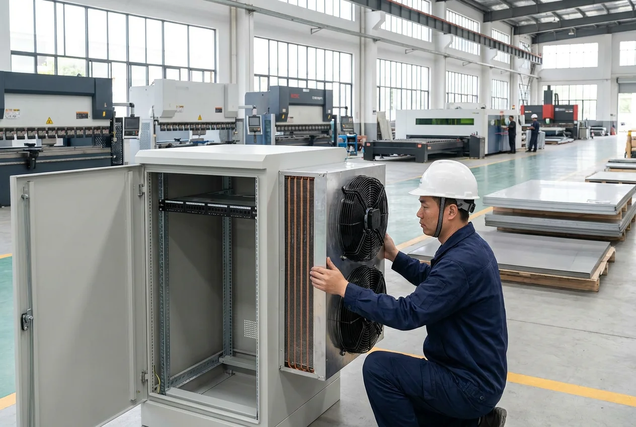
Reject weak options before detailing cutouts.
A late cooling decision can move apertures, reinforcement, doors, cable routes and drains at once. Four gates keep the shortlist honest before CAD becomes expensive.
Thermal feasibility
Use released heat loads, ambient profiles, solar exposure, temperature limits, duty cycles and equipment-supplier performance data.
Environmental separation
Decide whether outside air may enter, how contamination is controlled and what enclosure or system verification is required.
Power and controls
Confirm available power, starting and steady states, alarms, redundancy, control ownership and safe behavior after a fault.
Service model
Confirm filters, drains, replacement access, lifting, tools, consumables, site visits and the consequences of missed maintenance.
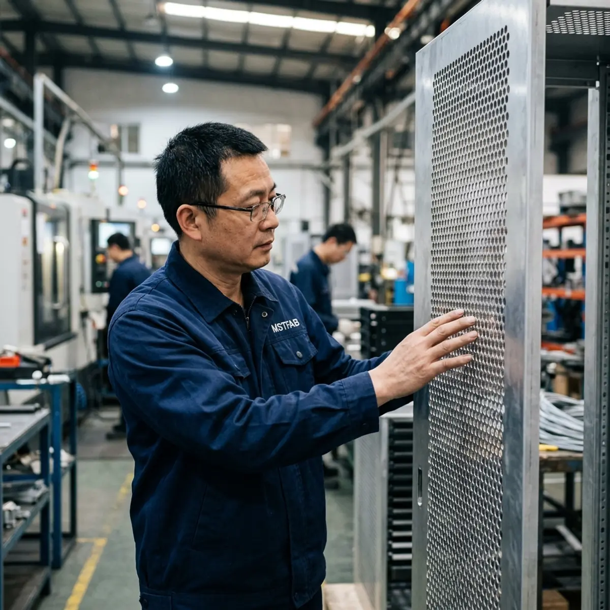
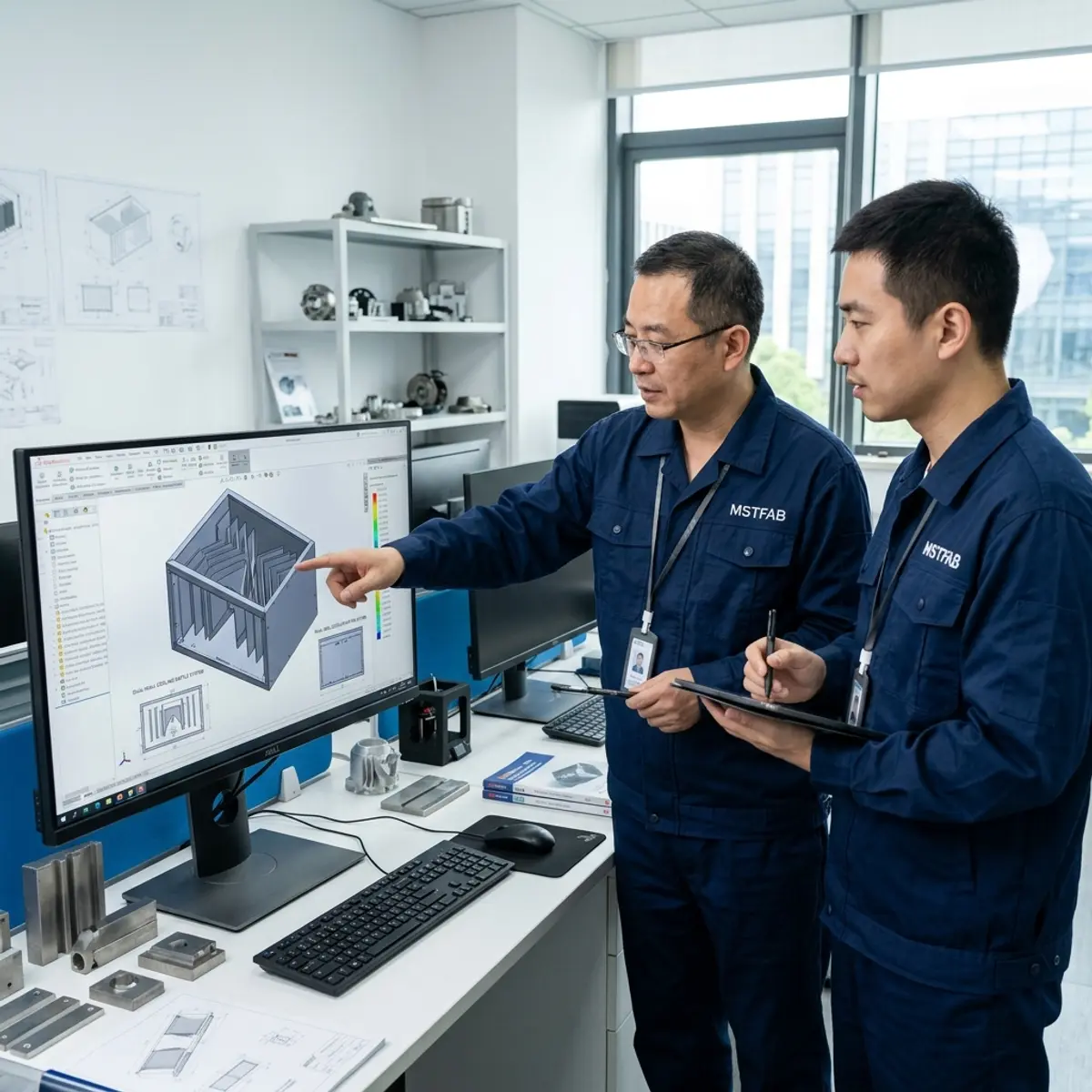
Release what the enclosure must physically support.
Review more than normal operation.
A cabinet may look fine during a steady-state calculation and still fail its service, transport or fault condition. The release package should show the states that change geometry or risk.
Expected equipment load, ambient range, solar condition, doors closed and the normal control sequence.
Fan, compressor, control or power loss; alarm response; permitted temperature excursion; and safe shutdown ownership.
Doors or panels open, filters removed, drains accessed and cooling equipment supported during replacement.
Cooling equipment installed or removed, temporary supports, lifting points, vibration restraint and protected interfaces.
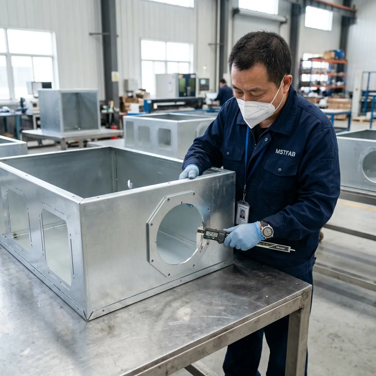
Connect the decision to revision-controlled proof.
Architecture choice and enclosure evidence should share the same equipment identity and drawing revision. Otherwise a correct inspection can verify the wrong configuration with great confidence.
Input record
Heat-load schedule, environmental profile, limits, architecture decision, cooling-equipment identity and open assumptions.
Interface review
Cutouts, datums, supports, fasteners, gasket lands, drains, cables, airflow paths, access and replacement envelopes.
First article
Check released cutout dimensions, specified flatness, mounting-hole positions, brackets and door or panel geometry. Agree on the required measurement records before ordering; installed-equipment and airflow tests belong to the integrator.
Validation handoff
Approved part and equipment revisions, deviations, installation controls and the responsible completed-system test plan.
Send the architecture decision with the cabinet files.
Provide a STEP or STP assembly, controlled 2D PDF drawings and buyer-controlled DXF or DWG flat-pattern information when applicable. Add the selected cooling-equipment drawing and the inputs that made the option acceptable.
- Equipment heat load by operating state
- Ambient, solar and contamination profile
- Internal limits and thermal owner
- Selected architecture and equipment model
- Mass, center of gravity and orientation
- Cutouts, datums, fasteners and gasket
- Drain, cable and airflow interfaces
- Service, replacement and fault states
- Inspection and validation responsibilities
- Quantity, destination and packing needs
MSTFAB does not publish one MOQ, lead time or tolerance for every project. Feasible commercial and manufacturing terms are confirmed from the released scope and quotation.
Outdoor telecom cooling architecture FAQ
Who selects and sizes the cooling architecture for an outdoor telecom enclosure?
The buyer, OEM or responsible thermal engineer selects and sizes the cooling architecture from the released equipment heat load, environmental profile, temperature limits, duty cycle, redundancy, maintenance and compliance requirements. MSTFAB uses the approved equipment and interface data to fabricate the drawing-defined mechanical parts and empty enclosure shell.
Does mounting a heat exchanger or air conditioner preserve an enclosure rating?
Not by itself. Any claimed rating depends on the applicable standard, complete assembly, cooling unit, gasket system, fasteners, penetrations, drainage, installation and verification plan. The released package should identify the responsible test and acceptance party.
Can a filtered-air or free-cooling design be treated as a sealed cabinet?
A design that intentionally exchanges outside air has a different contamination and moisture strategy from a separated-loop design. The responsible engineering team must define the required environmental separation, filters, pressure behavior, service interval and completed-system validation.
When should a TEC module be considered instead of a heat exchanger or air conditioner?
TEC suitability depends on the actual heat load, temperature lift, ambient profile, power budget, condensate strategy, control method and module supplier data. It can be shortlisted for some compact interfaces, but it should not be selected from cabinet size or a generic wattage table alone.
What cooling equipment does MSTFAB manufacture?
MSTFAB fabricates drawing-based sheet metal shells, panels, brackets and mounting cutouts. We do not supply, install or wire fans, heat exchangers, air conditioners or TEC modules. The buyer or its system integrator handles cooling equipment, insulation and completed-system validation.
Does MSTFAB publish one MOQ, lead time or tolerance for every cooling-ready telecom enclosure?
No. Cabinet size, material, interface geometry, reinforcement, hardware, sealing details, finishing route, inspection, quantity and packing affect the project. Feasible tolerances, quantity and schedule are confirmed from the released drawings and quotation.
Release the selected cooling method as controlled interfaces.
Send the thermal inputs, selected equipment data, cabinet model, interface drawings, operating states and required evidence. MSTFAB will review the drawing-defined sheet metal scope and return project-specific questions for quotation.
 WeChat Contact
 WhatsApp Me Directly