
The Magical Fantasy World of 3D CAD
Let’s be honest. Modern 3D CAD software is incredible. In SolidWorks or AutoCAD, you can design a totally seamless, impossibly thin, perfectly square telecom enclosure. It looks absolutely gorgeous rendering on your screen, floating in a magical, anti-gravity void where physics doesn’t exist.

Then, you export the STEP file, send it to a cheap, “yes-man” factory, and wait for your masterpiece to arrive.
When the pallets finally show up on your assembly floor, reality hits hard. Physics has entered the chat.
The metal is torn at the corners. The tapped holes you placed right next to a bend line look like squashed ovals, making it impossible to insert a screw. The doors don’t align, and the whole chassis is twisted like a heavy-duty metal pretzel.
What went wrong? You designed a beautiful enclosure, but nobody gave it a reality check. You skipped DFM sheet metal fabrication.
What the Heck is DFM? (And Why Do You Need It?)
DFM (Design for Manufacturability) is the brutal, honest, engineering reality check your CAD file desperately needs before a single laser fires. It is the process of optimizing your design so that real-world machines can actually cut, bend, and weld it without destroying the material—or your budget.
If a generic supplier just takes your raw file and hits “print,” they are guaranteeing rework. Real metal has thickness. Real metal springs back when you bend it.
Here are the classic “impossible” design flaws we catch every day:
1. The “Zero-Radius” Delusion
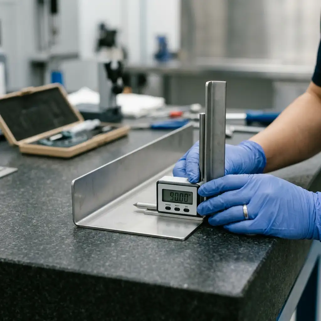
In CAD, you can draw an inside corner with a perfect 90-degree, razor-sharp edge (a 0mm radius). In the real world, if we try to force a heavy piece of steel into a zero-radius bend, the outer fibers of the metal will simply snap and crack.
The DFM Fix: We analyze your material thickness and specify the exact, mathematically correct inside bend radius so the metal forms smoothly and retains its structural load-bearing strength.
2. The Oval Hole Disaster
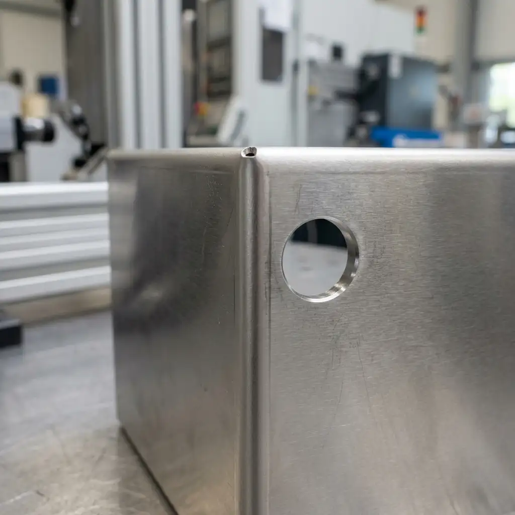
Engineers love putting ventilation cutouts, cable glands, or tapped mounting holes right next to a flange. But when the press brake comes down to bend that flange, the metal stretches. Your perfect circular hole gets pulled into an ugly oval, and your fasteners won’t fit.
The DFM Fix: We calculate the exact “hole-to-bend clearance” required for your specific material. We either move the hole slightly or design a strategic relief cut, ensuring your mounting points remain perfectly round and ready for frictionless assembly.
3. The “Tolerance Stack-Up” Nightmare
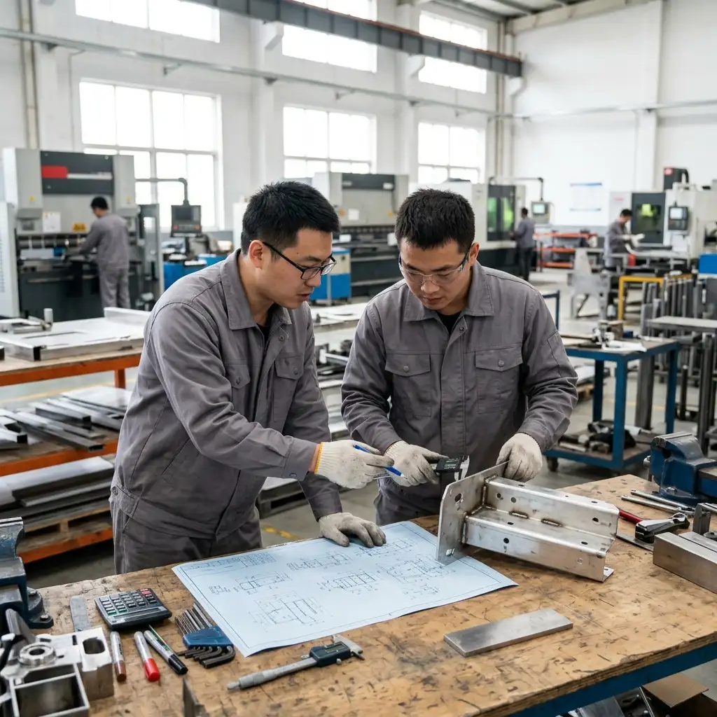
You designed three separate heavy-duty battery brackets that need to bolt together inside the cabinet. But you forgot that every time you bend metal, there is a microscopic deviation. By the third bend, those deviations stack up, and nothing aligns.
The DFM Fix: We proactively adjust the flat-pattern nesting and calculate precise springback allowances. We hold basic tolerances so tight that your internal payloads will drop in exactly where they belong.
The MST FAB Reality Check
We think manufacturing surprises are terrible. At MST FAB, we prefer things to be predictably boring and mathematically perfect.
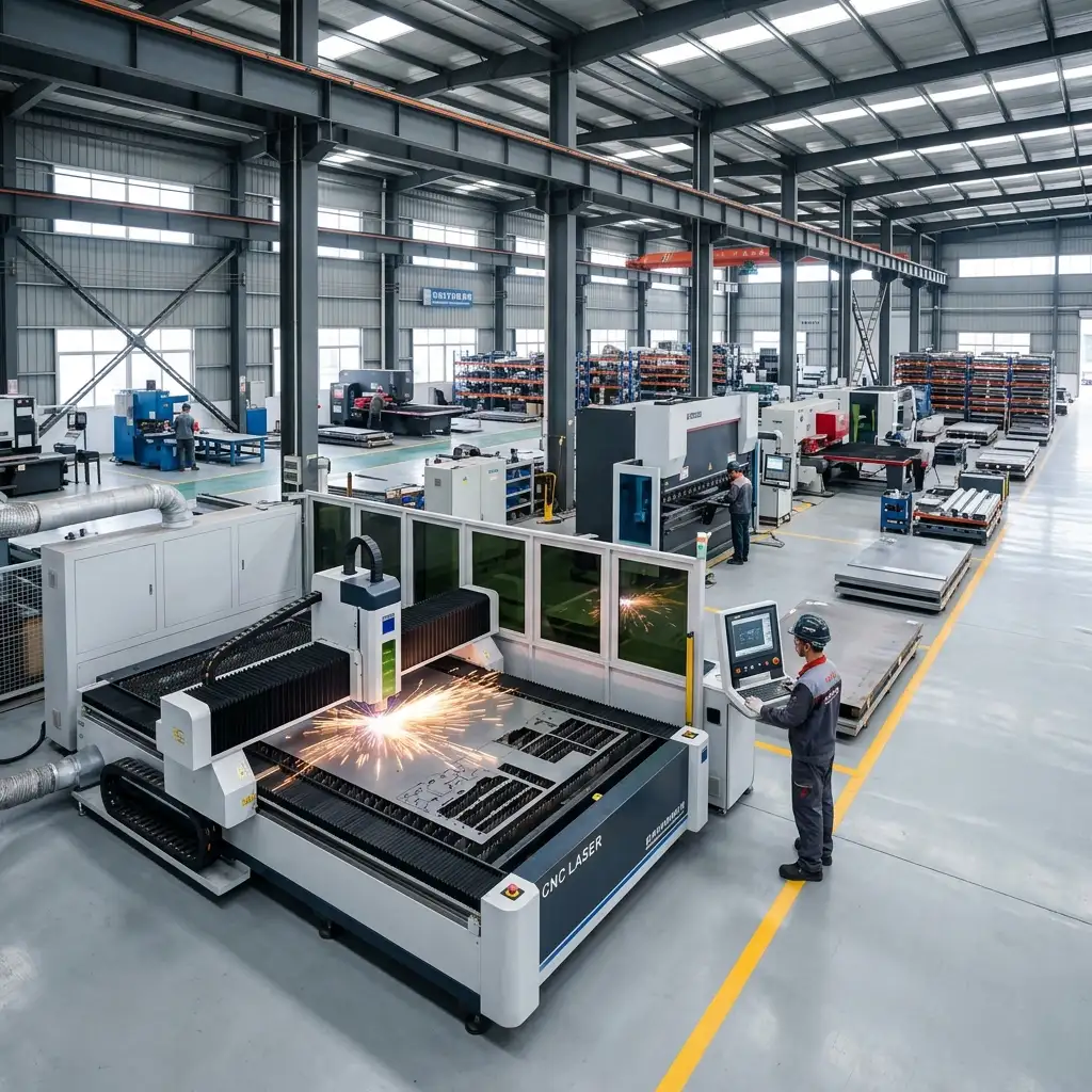
Operating from our precision-optimized 5000-square-meter facility in Guangzhou, China, we back our 23+ years of manufacturing heritage with a front-loaded engineering approach. We do not blindly cut metal. Within 48 hours of receiving your files, our engineering matrix runs a ruthless DFM audit to optimize your geometry, lower your tooling costs, and ensure your NEMA/IP-rated enclosures actually seal.
Our Ironclad Rule: We Protect Your IP
We achieve this level of mechanical mastery because we know our boundaries. We are pure-play precision sheet metal experts. We manufacture the metal enclosures and shells only.
We do not write software. We do not design circuitry. We will never ask for your logic programming, and we strictly exclude all internal electronic components from our scope. We dedicate 100% of our massive facility to forging the ultimate, indestructible metal armor. You supply the million-dollar brain; we supply the flawless, DFM-approved skull.
Stop Paying the “Rework Penalty”
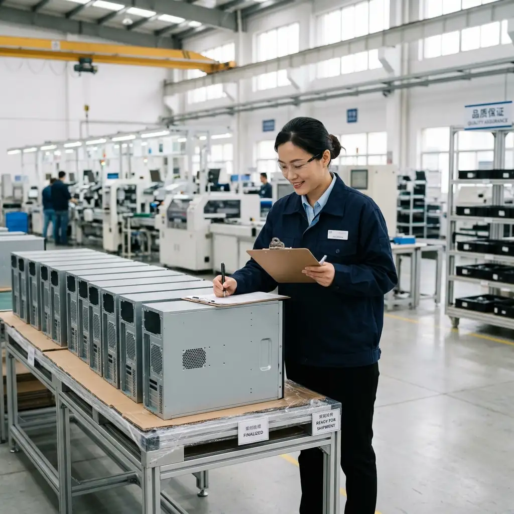
A design flaw caught in software costs nothing. A design flaw caught on your assembly floor costs thousands of dollars in wasted labor, scrapped metal, and delayed deployments.
Stop gambling on generic workshops that just say “yes” to impossible geometry. Upload your native 3D STEP or DWG files today. Let our engineering team give your CAD models the DFM reality check they need, and experience the sanity of true precision manufacturing.
Related engineering guide: Before releasing a drawing for quotation, review our guide to reading sheet metal drawings for thickness, bend notes, hole dimensions, tolerance callouts, and manufacturability checkpoints.
MSTFAB manufactures custom sheet metal enclosures, electrical cabinets, control boxes and industrial metal housings for OEM buyers.
 WeChat Contact
 WhatsApp Me Directly