
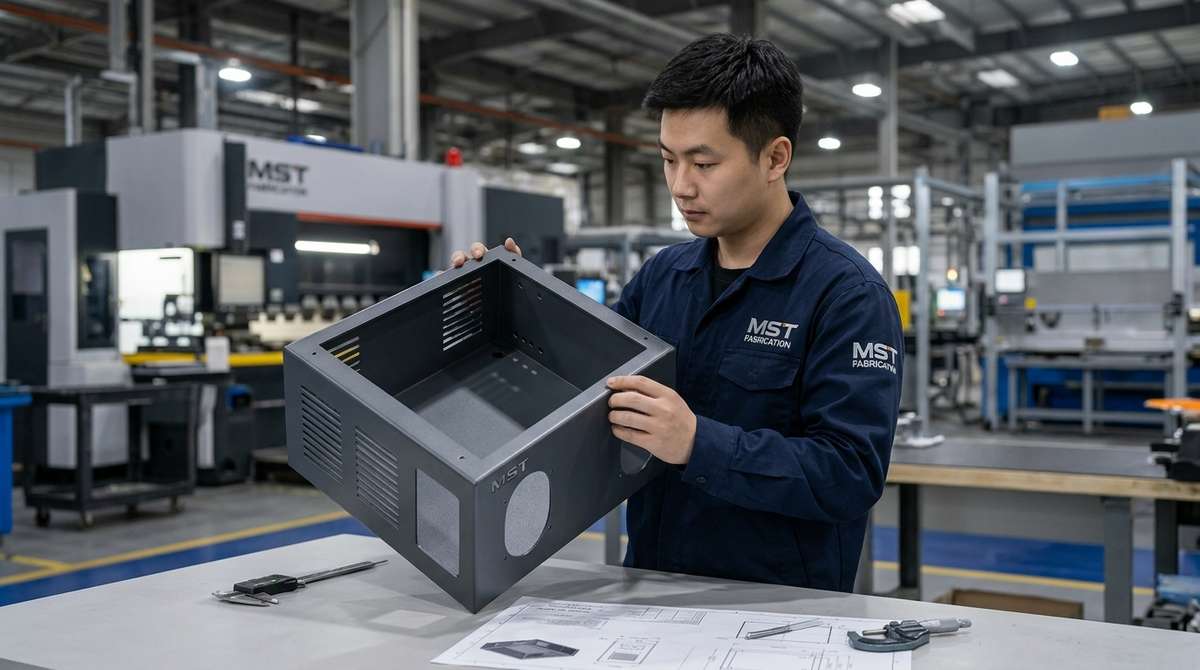
OEM buyer guide | unpopulated sheet metal enclosure shells
A custom PLC enclosure should begin as a well-defined sheet metal shell project. MSTFAB fabricates the cabinet body, door, mounting plate, brackets, studs, hardware interfaces and specified finish from customer drawings. The OEM or system integrator selects and installs the PLC, wiring and electrical equipment.
Build-to-print laser cutting, CNC bending, welding, hardware fit-up, powder coating or stainless finishing, dimensional inspection and export protection.
- No PLC or electrical component supply
- No wiring or control-panel integration
- No finished electrical system certification
This page is a design and RFQ checklist for buyers. For commercial production capability, materials and quotation details, visit the main PLC enclosure fabrication service. Projects using environmental protection claims should also review why IP65 and NEMA 4X are not interchangeable.
Start with the scope: enclosure shell, not a wired control cabinet
A clear responsibility split prevents slow quotations and awkward assumptions. If the request says only “PLC cabinet,” one supplier may quote a metal shell while another imagines a populated control panel. Those are very different products, with very different compliance responsibilities.

MSTFAB fabricates the metal enclosure
- Cabinet body, door, plinth and removable panels
- Blank mounting plate, brackets and sheet metal accessories
- Hinge, lock, gasket channel and specified hardware fit-up
- Cutouts, cable-entry plates, louvers and fan provisions
- Powder coating or stainless surface finishing
The OEM or integrator defines the electrical system
- PLC, drives, breakers, terminals and power supplies
- Wiring, cable routing and electrical assembly
- Thermal load and cooling-equipment selection
- Final IP/NEMA validation after component installation
- Electrical testing and control-panel certification
Six design checks before releasing a PLC enclosure shell
These checks resolve most of the expensive questions before metal is cut. The goal is not a heroic drawing review; it is simply to stop the hinge, cable gland and mounting plate from trying to occupy the same piece of space.
Envelope and mounting
Define overall size, wall or floor mounting, plinth geometry, lifting points, service clearances and interfaces with the machine frame.
Material and thickness
Choose carbon steel, galvanized steel, 304/316L stainless or aluminum from the environment, structure, finish and lifecycle needs.
Door and sealing details
Confirm hinge side, opening angle, lock type, folded return, gasket path, compression geometry and coating build at mating surfaces.
Cutouts and cable entry
Dimension HMI windows, glands, fans, vents and removable plates from controlled datums, with enough distance from bends and welds.
Internal metal interfaces
Locate the blank backplate, welded studs, PEM hardware, brackets and grounding points while preserving tool and assembly access.
Finish and first article
Mark visible surfaces, masking, color or grain direction, then approve dimensions, door gap and hardware fit before repeat production.
Turn the PLC enclosure drawing into a first-article release plan
A checklist is useful only when the supplier and buyer agree how to close each item. Link the inspection record to the enclosure part number, drawing revision and sample identifier. Record the acceptance condition before the sample is made, especially where coating or assembly affects fit.
| Mechanical interface | Define on the released drawing | Agree before sample approval |
|---|---|---|
| HMI opening | Cutout geometry, locating datums and mounting-hole pattern from the buyer’s selected component | Dimensional check and, where supplied, a fit check with the mating part; this does not validate the HMI electrically |
| Removable backplate | Mounting positions, hardware, removal direction and access for tools | Hole positions and installation/removal in the specified finished shell |
| Door and latch | Hinge and latch references, gap requirements and opening path | Post-finish alignment and operation against the agreed criteria |
| Cable-entry plate | Plate orientation, hole schedule, attachment and edge requirements | Opening positions, edge condition and mechanical access; cable installation remains buyer-controlled |
| Coated interfaces | Visible faces, masking, threaded features and buyer-defined contact areas | Agreed appearance and fit after finishing, not only measurements of the bare panel |
Example: an HMI opening changes after quotation
If the buyer selects a different display, do not update only the cutout width. Review the mounting pattern, rear component envelope, door reinforcement, tool access and the location of nearby bends. Ask the fabricator whether material has been cut and identify the effect on price and schedule. Release the revised drawing before the changed work proceeds.
This is an illustrative design-change scenario, not a customer case study. The component manufacturer’s installation information and the buyer’s approved design remain the controlling inputs.
Close open items before repeat production
For each discrepancy, record the drawing requirement, observed result, proposed action and buyer decision. An accepted sample deviation should state whether it applies only to that sample or changes the production specification. Do not treat silence, a workshop photograph or an informal message as approval to change the drawing.
Keep unresolved electrical or thermal questions separate from mechanical sample acceptance. A correctly positioned fan opening does not establish sufficient cooling, and an approved empty shell does not certify the completed control panel.
A build-to-print fabrication route
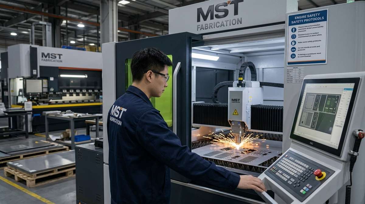
- Drawing and DFM review: check datums, bend access, cutout position, weld notes and hardware callouts.
- Cutting and forming: laser cut flat panels, CNC bend the shell and verify critical formed dimensions.
- Welding and finishing: control distortion, dress specified cosmetic areas, pretreat and apply the required finish.
- First article and packing: inspect shell squareness, door alignment, mounting interfaces and surface protection.
Related process references: sheet metal bending and sheet metal fabrication with powder coating.
Material and finish decisions
| Material route | Where it is commonly considered | Drawing details to define | Buyer watchpoint |
|---|---|---|---|
| Powder-coated carbon steel | Indoor or sheltered industrial installations where coating condition can be managed. | Grade, thickness, pretreatment, RAL color, texture, masking and visible surfaces. | Cut edges, threads and field scratches rely on the coating system. |
| Galvanized steel | Indoor or semi-sheltered use where a zinc-coated substrate is specified. | Coating designation, weld treatment and any additional powder coating. | Welding and grinding can disturb the zinc layer locally. |
| 304 stainless steel | Many industrial, washdown and humid environments. | Grade, finish, grain direction, weld treatment and passivation requirements. | Cosmetic faces and cross-contamination controls need clear acceptance criteria. |
| 316L stainless steel | Chloride, coastal or chemically aggressive exposure when justified by the application. | Actual exposure, finish, welding route and post-weld treatment. | Do not specify 316L by habit; confirm the environmental reason and acceptance standard. |
| 5052 aluminum | Weight-sensitive enclosures and corrosion-resistant fabricated housings. | Temper, thickness, bend radius, welding, anodizing or powder coating. | Thread strategy, distortion and electrical grounding interfaces differ from steel. |
For a deeper comparison, see stainless vs carbon steel PLC cabinet shells. Project tolerances should be assigned by function rather than applied everywhere; the sheet metal fabrication tolerance guide explains the tradeoffs.
What should be included in the RFQ package?
| RFQ item | Why the fabricator needs it | Useful evidence at approval |
|---|---|---|
| 3D STEP plus controlled 2D PDF | The 3D model defines geometry; the 2D drawing carries tolerances, welds, finish and inspection notes. | Drawing revision recorded on quotation, first article and inspection report. |
| Material, thickness and finish | These choices affect forming, welding, coating, appearance, corrosion strategy and price. | Material certificate or finish sample when the purchase specification requires it. |
| Critical-to-function dimensions | Door opening, mating holes, backplate patterns and machine interfaces deserve focused control. | First-article measurements tied to the controlled drawing. |
| Hardware schedule | Hinges, locks, PEM hardware, studs and removable panels need exact part numbers or interface dimensions. | Hardware fit and quantity checked before finish and packing. |
| Environment and responsibility split | Exposure guides material and finish; scope prevents electrical integration from being assumed. | Approved shell specification plus OEM validation after final equipment installation. |
| Prototype and repeat quantities | Fixtures, programming, nesting and inspection planning depend on realistic volume. | First article approved before repeat production is released. |
IP or NEMA wording needs care. MSTFAB can fabricate enclosure-shell features to approved drawings, including folded flanges, continuous welds, gasket channels and hardware interfaces. The final rating belongs to the completed assembly and must be validated by the responsible OEM or integrator after all openings, components and seals are installed.
Where PLC enclosure buyers usually lose time

Only a 3D model is supplied
The shape is visible, but no one knows the weld standard, finish, critical tolerances or which revision controls production. Add a concise 2D drawing.
The component layout changes late
A moved HMI or cable gland can invalidate bends, reinforcement and masking. Freeze external interfaces before the first article.
“Weatherproof” replaces a specification
That word does not define exposure, gasket geometry, coating, testing or who validates the final assembly. State the actual requirements.
Quote the enclosure shell from controlled drawings.
Send STEP and 2D PDF files with material, thickness, finish, quantities, critical interfaces and the intended environment. MSTFAB will review the sheet metal manufacturing route without assuming PLC supply or electrical integration.
Frequently asked questions
Does MSTFAB supply a complete wired PLC cabinet?
No. MSTFAB fabricates the unpopulated sheet metal enclosure shell and specified metal accessories. PLCs, electrical components, wiring, integration and final panel certification remain with the OEM or system integrator.
Can MSTFAB fabricate from an existing PLC enclosure drawing?
Yes. Supply a STEP model and controlled 2D PDF. The review focuses on manufacturability, bending access, cutouts, welds, hardware, finish and critical interfaces.
Can the shell include a mounting plate and hardware?
Yes. Blank mounting plates, brackets, studs, PEM fasteners, hinges, locks, gasket channels and removable sheet metal panels can be included when they are defined in the drawing and bill of materials.
Who is responsible for thermal design?
The OEM or integrator defines heat load, airflow and cooling equipment. MSTFAB fabricates the specified louvers, fan openings, heat-exchanger mounts and related sheet metal provisions.
What should be approved on the first article?
Check overall size, squareness, door gap, hinge and lock operation, mounting-plate fit, critical cutouts, hardware, finish, visible surfaces and packaging before repeat production.
MSTFAB mechanical enclosure procurement guide. This article addresses unpopulated enclosure-shell fabrication; project-specific electrical, environmental and compliance decisions remain with the responsible OEM engineering team.
 WeChat Contact
 WhatsApp Me Directly