
A useful prototype is a physical answer, not a small metal souvenir. It should tell engineering whether the enclosure fits, the bracket lands, the door clears and the hardware remains accessible.
MSTFAB manufactures custom sheet metal prototypes with fast turnaround for unpopulated shells, panels, brackets, covers, chassis and welded housings. We build the metal parts around the buyer’s product; we do not sell finished electrical, medical, telecom, automation or EV equipment.
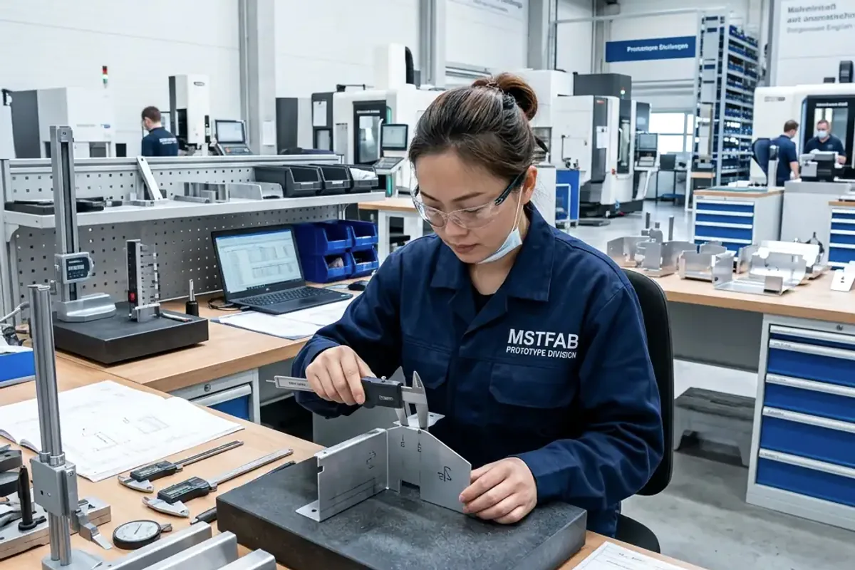
What Is a Fast-Turnaround Custom Sheet Metal Prototype?
It is a build-to-print physical sample made with production-relevant sheet metal processes so the buyer can validate geometry, assembly and fabrication risk. The route may include CAD review, laser cutting, CNC bending, welding, PEM hardware, surface finishing, trial assembly and dimensional inspection.
For straightforward prototypes using available material, standard tooling and clear drawings, MSTFAB commonly evaluates a typical production window of about 7-15 working days after material, quantity, finish and inspection requirements are confirmed. Simple cut-and-bend parts may move sooner. Complex welded housings, special material or custom finishing can take longer. A prototype that arrives early but does not fit is not a fast result; it is scrap with good calendar performance.
A Six-Step Functional Prototype Workflow
A fast prototype needs a clear route from files to approval. These six stages keep design questions, fabrication and physical validation connected instead of becoming separate email threads.
Release one revision
Confirm the STEP model, controlled drawing, material, thickness, quantity, finish and the dimensions that affect fit.
Find risks before cutting
Review bend radius, flange length, hole position, tooling access, weld sequence, hardware and coating buildup.
Use relevant processes
Select material, laser cutting, bending, welding, hardware and finish that represent the likely production method.
Control each handoff
Verify units, flat pattern, bend direction, component orientation and approved changes through fabrication.
Test the real interfaces
Measure critical dimensions and check holes, doors, mating parts, threads, hardware, clearances and visible surfaces.
Turn findings into revision
Move accepted changes into controlled files before pilot or low-volume production begins.
Start with Files That Answer Manufacturing Questions
For the strongest review, send a STEP or STP model for geometry and a controlled 2D PDF drawing for requirements. DXF and DWG files help with flat profiles, but they do not always show bend direction, finished dimensions or assembly intent.
The drawing should define material grade, thickness, critical dimensions, tolerances, threads, hardware, weld notes, visible surfaces, finish, inspection and revision. If only a STEP or DXF file is available, MSTFAB can begin a preliminary review and identify what is missing.
- One approved revision across 3D and 2D files
- Critical dimensions tied to assembly function
- Hardware part numbers and installation direction
- Finish, masking and cosmetic surface notes
See how we handle custom sheet metal fabrication from CAD files.
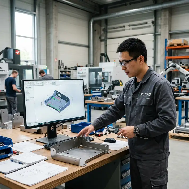
What Should a Functional Prototype Prove?
Questions the metal prototype can answer
- Do overall dimensions and bend orientation match the assembly?
- Do mounting holes, doors, covers and cable openings align?
- Can hardware be installed and serviced after forming?
- Does the welded structure stay square enough for mating parts?
- Are visible surfaces, texture and finish acceptable?
Questions outside the unpopulated shell scope
- Electrical performance of buyer-installed electronics
- Battery, telecom, medical or charging-system certification
- Finished equipment operation after buyer integration
- Any unapproved substitution of material, hardware or finish
- A guaranteed schedule before drawings and supply are reviewed
For the full metal manufacturing boundary, review our custom sheet metal fabrication service.
Which Prototype Projects Fit a Shorter Route?
Usually easier to schedule
- Brackets, panels, trays, covers and mounting plates
- Small unpopulated chassis and enclosure shells
- Standard material grades and common thicknesses
- Existing press brake tooling and accessible bend geometry
- Functional finish or standard powder colors
Usually need more planning
- Large welded frames with tight squareness or door gaps
- Fully blended cosmetic welds on visible surfaces
- Uncommon alloys, nominated stock or special thicknesses
- Custom color matching, detailed masking or outside testing
- Assemblies waiting for buyer-supplied components
Buyer shortcut that actually works: identify what the prototype must prove. If the purpose is fit, do not spend a week debating a showroom finish. If the purpose is customer approval, do not ship raw steel and call it close enough.
Laser Cutting and CNC Bending Build the Core Geometry
Laser cutting creates profiles, holes, slots, ventilation patterns and connector openings without hard tooling for many prototype parts. CNC bending forms brackets, panels, doors, covers and chassis walls using controlled tooling and bend sequences.
Before release, MSTFAB checks scale, units, contours, bend direction, flange length and tool access. A clean flat pattern helps, but the final geometry still needs a formed model or drawing. A DXF cannot politely explain which way a flange should point.
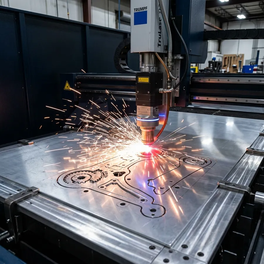
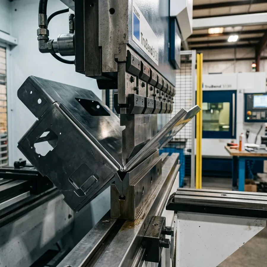
Process details are available on our laser cutting and CNC bending page.
Welding and Hardware Must Match the Intended Assembly
A prototype assembly may use TIG, MIG or spot welding depending on material, joint and appearance. Fixture design, weld sequence and heat input affect squareness and fit. Buyers should identify whether welds can remain visible, require cleaning or must be blended for a cosmetic surface.
PEM nuts, studs, rivet nuts, hinges, latches and threaded inserts should use the intended production part numbers whenever practical. That confirms access, thread engagement, component clearance and whether the hardware survives the planned finish.
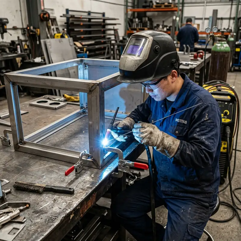
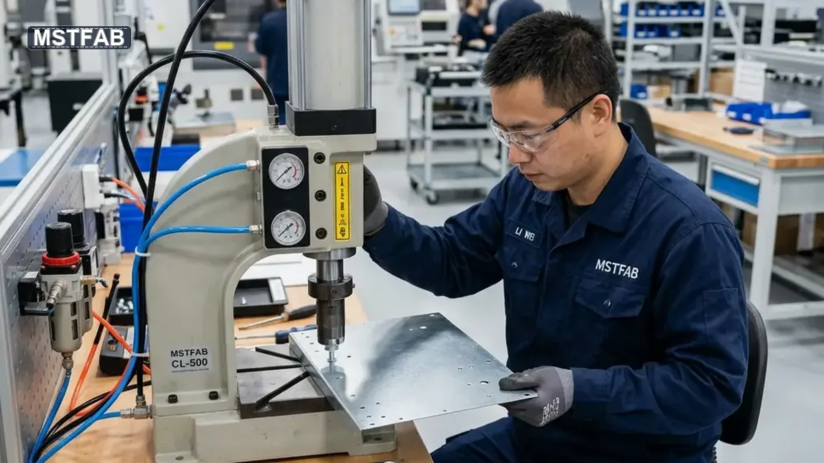
For joining options and weld-finish planning, see sheet metal welding services.
Physical Validation Is the Reason to Build the Part
Inspection should focus on features that affect function: datums, hole positions, door movement, internal clearance, hardware, threads, weld quality and visible surfaces. A photo is useful evidence, but it cannot test thread engagement or assembly fit, no matter how optimistic the email sounds.
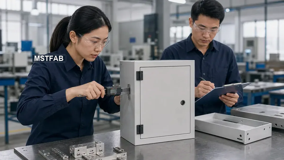
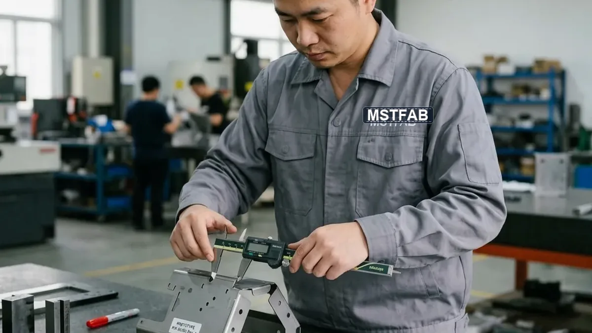
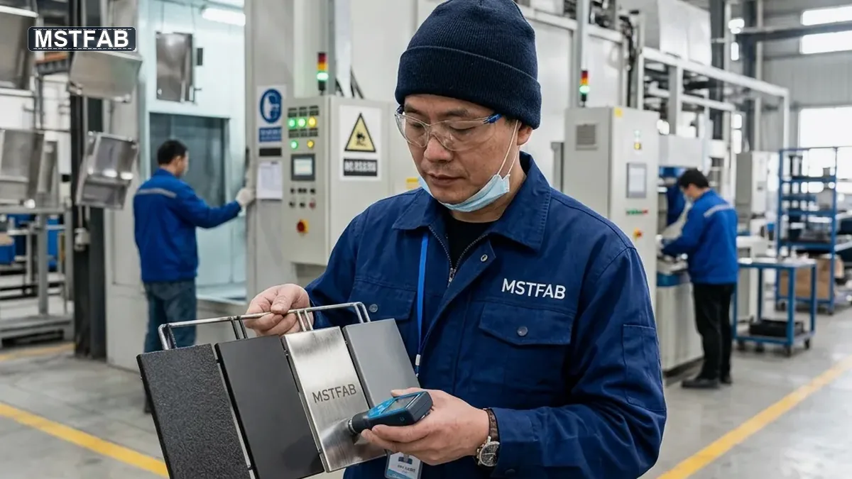
Our sheet metal fabrication tolerance guide explains why laser-cut, bent, welded and coated features need different controls.
Trust Table: Evidence a Prototype Buyer Should Expect
| Buyer concern | MSTFAB evidence | Buyer approval |
|---|---|---|
| Correct revision | Drawing number, revision and matching file set confirmed before release. | Close obsolete files and approve one controlled package. |
| Manufacturable design | DFM feedback for bends, holes, welds, hardware, finish and access. | Approve any proposed change before metal is cut. |
| Functional fit | Inspection focused on assembly datums, mating features and critical clearances. | Test the part in the real assembly and report findings by revision. |
| Production relevance | Material and fabrication route selected to represent the likely repeat process. | Approve the manufacturing route, not only the sample appearance. |
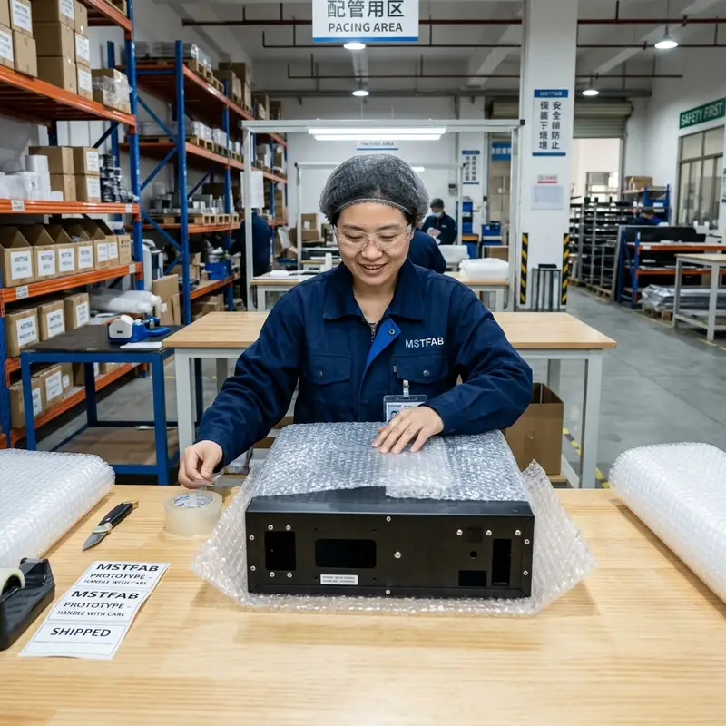
| Protected delivery | Surface protection and packing matched to the part and finish. | Confirm destination, shipping method and handling sensitivity. |
Move Test Findings into the Next Drawing Revision
After the buyer tests the prototype, accepted changes should be added to the controlled drawings. Update dimensions, tolerances, hardware, finish, weld notes and inspection points before a pilot or low-volume batch begins.
Verbal comments and marked photos are useful during review, but they are not the production master. A change that never reaches the drawing is a future argument wearing a part number.
- Record accepted DFM and assembly changes
- Update the revision in every released file
- Define critical inspection and finish references
- Approve packaging for visible or delicate parts
What to Send for a Fast Prototype Review
A complete RFQ package reduces quotation questions and prevents avoidable revisions after production starts.
CAD and drawings
STEP or STP model, controlled PDF drawing, DXF or DWG where relevant, drawing number and revision.
Prototype definition
Material, thickness, quantity, critical tolerances, hardware, weld notes, visible surfaces, finish and inspection needs.
Decision and delivery
What the prototype must prove, required factory or arrival date, destination, shipping method and packing expectations.
One useful date note: factory production, international shipping, customs and local delivery are different clocks. State whether the required date means factory completion or arrival at your facility.
Frequently Asked Questions
Can every custom sheet metal prototype be produced in 7-15 days?
No. The 7-15 working-day range is a typical planning reference for suitable projects after requirements are confirmed. Complex welding, special material, custom finish, buyer approvals, detailed reports or component availability can require more time.
What files help MSTFAB review a functional prototype quickly?
A STEP or STP model plus a controlled 2D PDF drawing is the strongest combination. Include material, thickness, quantity, critical dimensions, hardware, welding, finish, inspection and revision.
Does MSTFAB manufacture a finished equipment prototype?
No. MSTFAB manufactures the custom sheet metal shells, panels, brackets, covers, chassis, frames and mechanical assemblies from buyer drawings. The buyer normally installs electronics and other finished-product components.
Should the prototype use the intended production material?
Whenever practical, yes. The intended material, thickness, hardware and fabrication route provide more reliable information for fit and later production. Any temporary substitution should be discussed and approved.
What dimensions should be inspected first?
Prioritize the dimensions that affect assembly, mounting, doors, hinges, connectors, hardware, internal clearance and mating parts. Applying the tightest tolerance to every feature can add cost without improving the test.
What happens after the prototype is approved?
Accepted changes should be added to the controlled drawing revision. The approved route, material, hardware, finish and critical inspection points can then support pilot or low-volume production.
Related Manufacturing References
These references cover the core fabrication decisions without filling the article with loosely related links.
Need a Prototype That Answers the Next Engineering Question?
Send the CAD files, controlled drawing, material, finish, quantity and what the prototype must prove. MSTFAB will review the fastest practical route and identify risks before cutting.
 WeChat Contact
 WhatsApp Me Directly