
How does an integrated CAD-to-production digital thread streamline custom sheet metal fabrication?
An integrated CAD-to-production workflow links 3D digital design intent directly to factory CNC automation across six stages: (1) native CAD/STEP import and automated DFM rule checking (verifying uniform gauge, minimum bend radii, and hole-to-bend spacing), (2) algorithmic flat pattern unfolding utilizing empirical shop-calibrated K-factors, (3) automated dynamic nesting on 15 kW fiber lasers, (4) 3D collision-simulated CNC press brake forming, (5) robotic/manual fixture welding, and (6) 3D coordinate measuring machine (CMM) and laser scanning inspection comparing finished physical parts against the nominal CAD model.
1. The Digital Thread in Modern Sheet Metal Manufacturing
Traditional sheet metal fabrication was plagued by manual re-entry of data: engineers created 3D models, exported 2D drawings, which drafting technicians then redrew into flat patterns, before machine operators manually punched coordinates into press brake controllers. Every manual handoff introduced transcription errors, interpretation mistakes, and revision lag.
Today, MSTFAB operates a continuous Digital Thread. Digital CAD geometry flows seamlessly from the customer’s design engineering workstation through automated DFM analysis, CAM nesting, fiber laser cutting, multi-axis CNC bending, hardware clinching, welding, and automated CMM inspection—ensuring zero data loss and guaranteed first-article fidelity.

2. Stage 1: Automated DFM & CAD Model Validation
When a customer uploads a 3D CAD file (STEP, SolidWorks, or Inventor), our automated manufacturing software conducts an instantaneous geometric audit:

- Uniform Gauge Check: Confirms the solid model consists of a single, continuous sheet thickness.
- Bend Radius Audit: Replaces CAD default sharp corners with tooling-compatible standard radii (IR ≥ 1.0t for steel; 1.5t for aluminum).
- Hole Proximity Check: Flags any cutouts positioned closer than 2.5t + r to a bend line, recommending relief slots to prevent oval hole stretching.
- Flange Height Validation: Ensures all return flanges meet the minimum press brake die bridge requirement: hmin ≥ 4.0t.
3. Stage 2: K-Factor Unfolding & High-Speed Laser Cutting
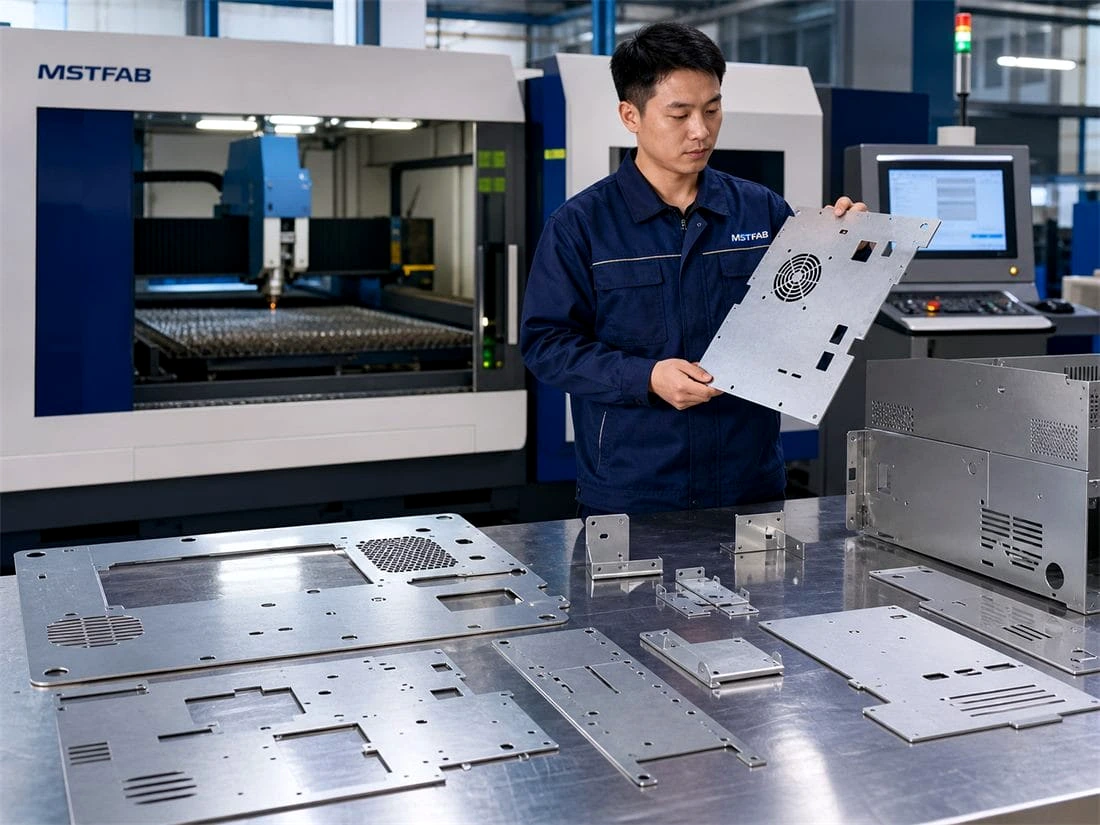
The CAD solid model is unfolded into an exact 2D flat pattern using shop-calibrated K-factors. Blanks are automatically nested on high-yield sheet layouts to minimize material scrap.
4. Stage 3: Collision-Free Press Brake Forming
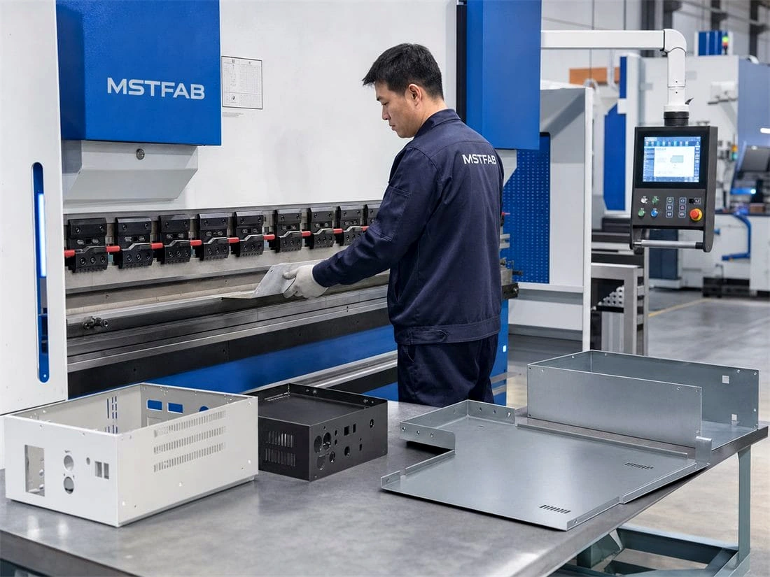
The 3D CAD model directly generates the CNC press brake program. Tooling stations, backgauge coordinates, and bend sequences are verified virtually before forming begins, eliminating tooling collisions on deep enclosure returns.
5. Stage 4: 3D CMM & Laser Scan Quality Verification
Finished parts and welded assemblies are inspected against the original nominal 3D CAD model using 3D Coordinate Measuring Machines (CMM) and laser scanning arms:
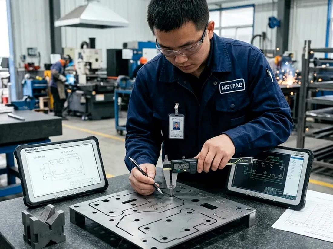
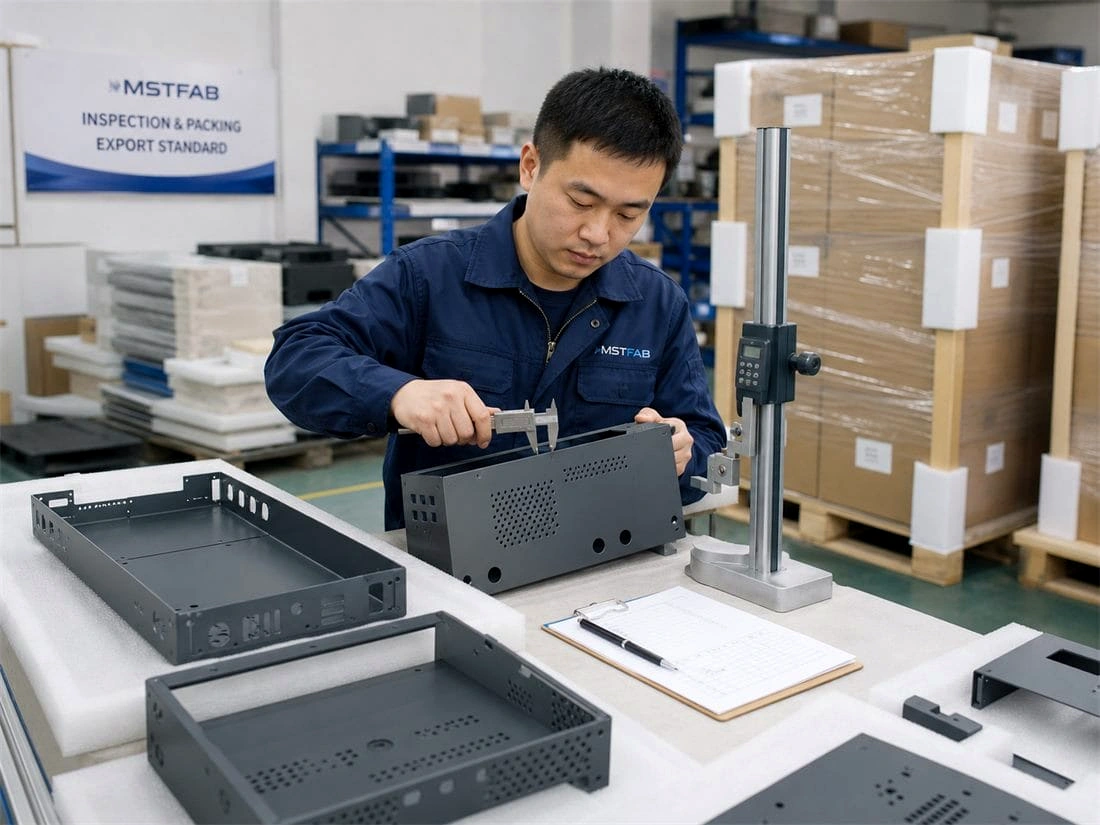
The CMM touch-probes critical GD&T datums, standoff heights, and hole true positions, generating color-mapped deviation reports that guarantee 100% assembly fit before parts are packed for export.
6. CAD-to-Production Stage & Tolerance Matrix
MSTFAB enforces strict quality tolerances at each phase of the digital workflow:
| Workflow Stage | Digital Tool / Machine | Process Tolerance | Quality Deliverable |
|---|---|---|---|
| 1. CAD Import & DFM | Automated 3D CAM Parser | Mathematical exact B-Rep | DFM manufacturability scorecard & quote |
| 2. Laser Cutting | 15 kW CNC Fiber Laser | ±0.05 mm hole pitch | Dross-free, oxide-free deburred blanks |
| 3. CNC Press Brake | Multi-Axis Press Brake | ±0.25 mm flange; ±0.3° angle | Real-time angle-corrected formed panels |
| 4. Hardware & Weld | Hydraulic Press / TIG Welding | Δ ≤ 0.5 mm squareness | Rigid monolithic chassis assemblies |
| 5. CMM Verification | 3D CMM / Laser Scanner | ±0.01 mm volumetric accuracy | AS9102 First Article Inspection Report (FAIR) |
Transform Your CAD Files into Finished Metal Parts
MSTFAB connects your 3D CAD models directly to high-precision laser cutting, CNC press brake forming, and certified welding. Upload your STEP and DXF files today for instant DFM analysis and volume manufacturing.
 WeChat Contact
 WhatsApp Me Directly