
CNC Machining and Sheet Metal Assembly: A Fit Verification Checklist
A precision-machined component can meet its own drawing and still fail to fit a sheet metal assembly. The cause may involve the mating part, the way requirements are defined, the inspection condition or a revision mismatch. Review the shared interface instead of assuming that a tighter machining tolerance alone will solve the problem.
Quick answer: identify both part revisions, the surfaces that locate the assembly, the critical hole and thread requirements, the finish condition and the agreed fit check. Inspect the relevant features on each component and verify the assembled interface. One supplier can simplify coordination, but neither single-source nor multi-supplier production guarantees a particular result.
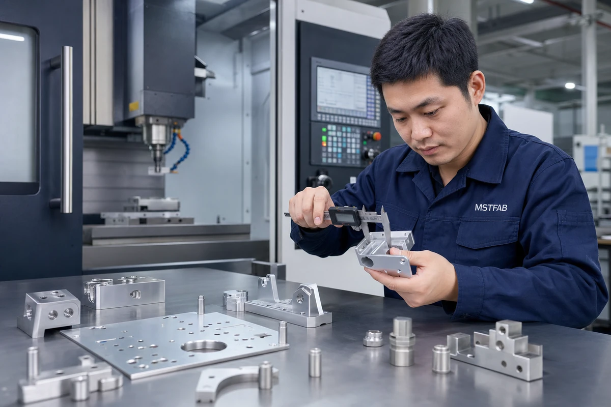
Define the Interface Before Tightening Tolerances
Start with what locates and constrains the components in service. Identify mounting faces, locating features, fasteners and any required clearance. Make sure the drawings define the relationships needed for the assembly rather than only the overall dimensions of each loose part.
Record the applicable drawing standard and edition, units, datums and critical requirements. If a dimension or geometric tolerance is ambiguous, resolve it with the responsible designer before production. A general workshop tolerance is not a substitute for an interface-specific requirement.
If the process route is still undecided, the machining vs sheet metal fabrication guide addresses that choice. This checklist assumes the assembly already needs both types of component and focuses on their fit verification.
Machined-Part and Sheet-Metal Interface Checklist
| Interface item | What to agree | Evidence to request |
|---|---|---|
| Part identity and revision | The released component drawings, model revisions and mating part numbers. | An approved file list connected to the inspection records and assembly check. |
| Locating and mounting faces | Functional datums, contact surfaces and the condition in which they are evaluated. | Relevant form, orientation and dimension results using the agreed reference scheme. |
| Hole pattern and clearance | Size, location and relationship to the features that locate the assembly. | Component measurements plus the agreed check against the mating interface. |
| Threads and installed hardware | Thread designation, applicable class, depth or engagement requirements and hardware identity. | The specified verification method and any installation checks included in the order. |
| Finish and exclusions | Whether requirements apply before or after coating, plating or anodizing, including any masked areas. | Finished-condition measurements and confirmation of the defined exclusions. |
| Assembly acceptance | The actual parts or approved gauge used, assembly condition and acceptance criteria. | A traceable result identifying which revisions and components were checked together. |
Measure in the Condition That Controls Fit
A dimension measured while a part is restrained in a fixture may not describe its released condition. Protolabs notes that clamping forces and internal stresses can affect the flatness of machined parts after removal, especially for thin-walled geometry. Confirm which inspection condition the design requires rather than treating every fixture result as a final acceptance result.
The sheet metal component has its own forming, welding and finishing history. If its interface changes at a later operation, compare measurements at the relevant stages. Do not use a flat-blank inspection as the sole evidence for a finished bent or welded assembly.
For the formed-part dimensional chain, use the sheet metal bending tolerance stack-up guide. Tightening one CNC dimension does not automatically resolve variation elsewhere in that chain.
Do Not Apply a Universal Coating or Thread Offset
Specify the finished requirement and discuss how the selected finish affects the relevant interface with the machining and finishing providers. Mark contact surfaces, threads, bores and close-fit locations that need special consideration. Record whether the agreed result is assessed before or after finishing.
A blanket instruction to subtract the nominal coating thickness from every thread or hole is not a complete manufacturing specification. The feature geometry, finish system and acceptance method need to be considered together. Approve any proposed allowance or masking change before the manufacturing documents are released.
Example: a Machined Spacer on a Bent Mounting Bracket
Illustrative example, not a customer case: a machined spacer mounts to a coated sheet metal bracket. The spacer inspection report shows acceptable dimensions, but the assembly rocks and a fastener will not enter freely.
Identify the exact spacer and bracket revisions. Check the locating face, hole relationship and finished condition of both parts using the agreed requirements. Record the assembly condition and compare it with the inspection reports. Do not conclude that the CNC part is wrong simply because it is the more expensive component, or enlarge the bracket hole without design approval.
After an approved correction, repeat the relevant component checks and the defined interface check. Keep those results connected; a photograph of two parts touching is not a dimensional report or proof of batch-wide interchangeability.
What Belongs in the Assembly-Fit Review Record?
- Identity: each part number, revision and applicable lot or sample identification.
- Requirement: the interface feature, drawing reference and agreed acceptance criterion.
- Method: reference scheme, support or restraint, finish condition and measurement approach.
- Results: the relevant component measurements and the specified assembly or gauge result.
- Decision: acceptance, open issue or approved corrective action, including the responsible approver.
Agree the report, sampling and fit-check scope in the quotation. Do not assume that every order includes a CMM report, a full statistical study or inspection of every feature. Lead time and documentation requirements should be confirmed for the actual project.
CNC and Sheet Metal Fit Questions
Does manufacturing both components in one factory eliminate mismatch?
No. It may simplify communication, but the drawings, measurement references, process controls and acceptance evidence still need to agree. A shared supplier is not a substitute for a defined interface.
Should every machined dimension have the tightest possible tolerance?
No. Identify what controls function and apply the necessary requirements through the design. Unnecessary precision can add work without correcting a different mating-part or reference problem.
Does a successful sample fit prove every batch will fit?
It establishes the result for the components and conditions checked. Agree the additional evidence needed for the intended production scope and repeat orders; do not infer a batch defect rate from one sample.
Send the Mating Parts, Not Only One CAD File
Send MSTFAB the available component and assembly drawings, revisions, quantities, materials, finishes and fit requirements. Identify any required inspection reports or sample checks. Manufacturing scope is described on our CNC machining services page.
Request an Interface ReviewTechnical Reference
Protolabs’ machining tolerance guide explains mating-part requirements, geometric controls and released-part flatness considerations. Its listed tolerances and equipment-related capabilities are not MSTFAB specifications. Confirm requirements and inspection scope for the actual order.
 WeChat Contact
 WhatsApp Me Directly