
NEMA 12 JUNCTION BOX DFM — EXECUTIVE TECHNICAL BRIEF
NEMA 12 galvanized steel junction boxes protect terminal blocks, remote I/O nodes, and motor splices inside manufacturing plants against circulating dust, falling dirt, and dripping non-corrosive oil or CNC coolant mist. Yet field failures frequently trace back to subtle sheet metal DFM errors: over-ground mitered corner welds that leave pinholes for oil seepage, shallow door flanges that fail to seat closed-cell seals evenly, and latch spacings over 350 mm that let covers bow open under gasket rebound. At MSTFAB in Guangzhou, build-to-print NEMA 12-style mechanical shells pair 1.5–2.0 mm SGCC Z180–Z275 steel with interlocking laser-tabbed corners, low-heat pulse-TIG/CuSi3 weldments, formed 90° knife-edge return gutters (8–10 mm throat), and seamless FIPFG polyurethane gaskets compressed 25–35%. Every build ships with EN 10204 3.1 traceability and IP54/IP55 witness verification to support OEM UL 508A/50E programs.
- Seamless FIPFG Gasket Compression: Formed-in-place foam-gasketed (FIPFG) polyurethane seals dispensed directly onto 1.5 mm galvanized lids eliminate butt-joint corner leaks, compressing 25–35% (2.0–2.8 mm deflection) against a 2.5 mm formed knife-edge body flange for dust-and-oil tightness.
- HAZ-Controlled Corner Seam Welds: Self-fixturing laser-tabbed box miters with ≤ 0.15 mm fit-up gap are pulse-TIG or CuSi3 silicon-bronze welded over copper chill bars, limiting zinc burn-off HAZ to ≤ 4.0 mm and passing 100% light-box leak verification prior to priming.
- Anti-Bow Latch & Cover Rigidity: Covers exceeding 350 mm span incorporate 12 mm hemmed return edges and spot-welded internal stiffeners with quarter-turn compression latches or captive M5 screws pitched ≤ 250 mm apart, holding midpoint deflection below 0.3 mm under gasket load.
- Oil-Resistant Coated Galvanized Defense: SGCC Z180–Z275 substrates receive Cr-free zirconium pretreatment, zinc-rich weld-seam repair, and 70–90 µm RAL 7035 oil-resistant epoxy-polyester powder coating, backed by EN 10204 3.1 certs and IP54/IP55 witness data for OEM UL 50E/508A submittals.
Every project at MSTFAB includes a complimentary 24-hour CAD Design-for-Manufacturing (DFM) audit, heat-number-traceable EN 10204 3.1 mill certificates, and a ballooned First Article Inspection (FAI) report prior to volume release.
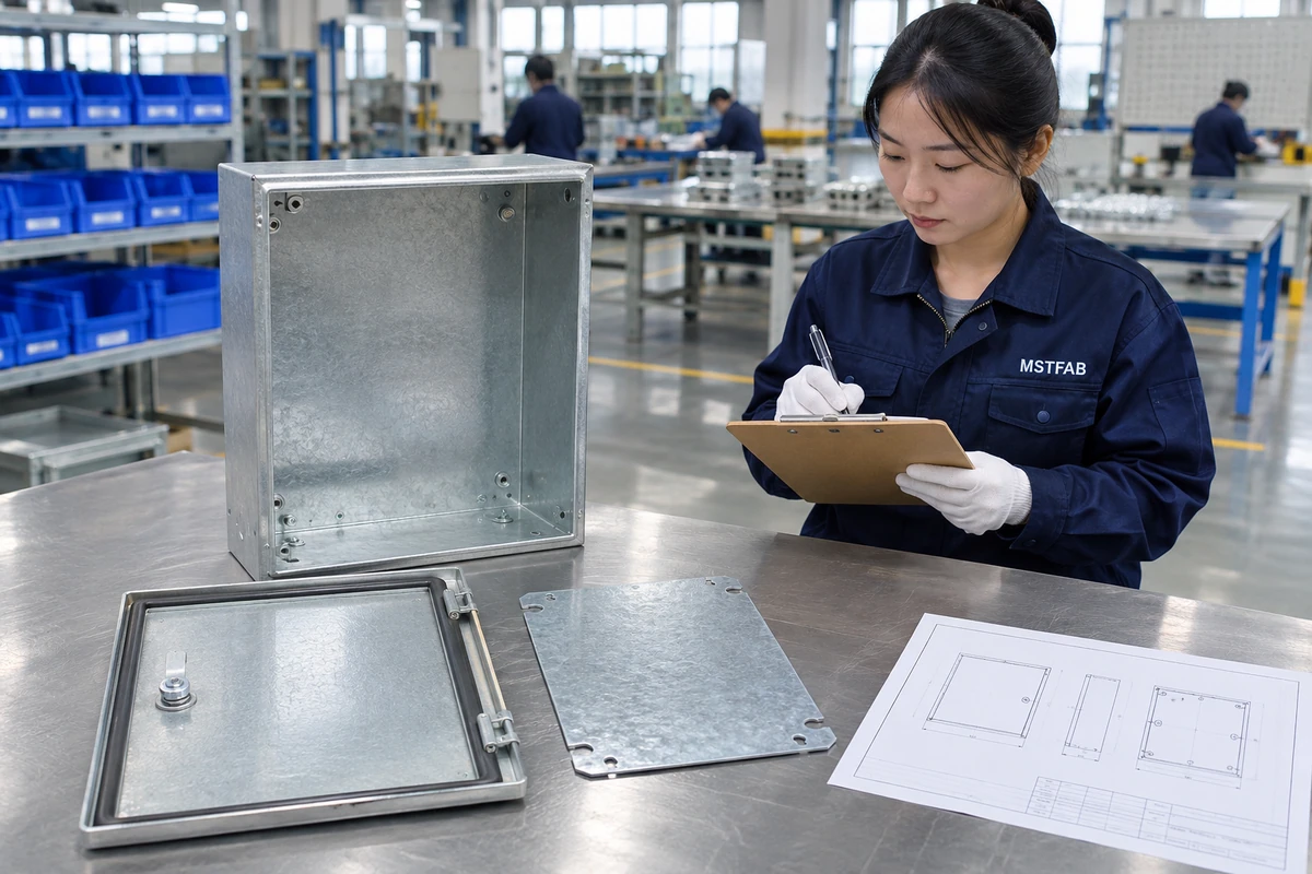
01 / Engineering Specifications & Comparison Matrix
NEMA 12 Galvanized Junction Box Sealing & Structural Specification Matrix
Designing a galvanized steel junction box to meet NEMA 250 Type 12—and its closest industrial counterpart, IEC 60529 IP54/IP55—requires far more than specifying a generic rubber strip inside a folded sheet metal lid. In CNC machining centers, stamping lines, and automotive powertrain bays, fine metallic dust and emulsified cutting oils exploit any interruption in gasket land flatness, any unsealed corner weld micro-porosity, or any unsupported conduit wall that flexes when locknuts are wrenched tight. Moreover, galvanized steel introduces welding heat-affected zone (HAZ) challenges: excessive amperage vaporizes the protective zinc envelope up to 15 mm back from the corner, turning the very seam meant to stop moisture into a premature rust initiator. The six-zone engineering matrix below defines the exact flange geometry, weldment controls, gasket compression targets, hardware spacing, and inspection checks MSTFAB enforces on every NEMA 12-style galvanized junction box shell.
Each parameter below is verified during incoming raw material quarantine, in-process CNC stage checks, and final First Article Inspection (FAI) before shipment release:
| Engineering Parameter / Zone | Material & Process Specification | Target Tolerance / Performance Standard | Inspection Method & OEM Value |
|---|---|---|---|
| 01 — Box Body & Interlocking Corner Seam | 1.5 mm or 2.0 mm SGCC DX51D+Z180–Z275 (ASTM A653 G60/G90) folded into a 4-sided pan with self-fixturing laser corner tabs and continuous CuSi3/pulse-TIG corner seam welds. | Tab fit-up gap ≤ 0.15 mm before welding; heat-affected zone (HAZ) ≤ 4.0 mm width; remaining metal thickness after flush corner dressing ≥ 90% of nominal wall gauge. | 100% dark-room high-lumen light-box pinhole check on raw welded shells, ultrasonic or micrometer corner-wall verification during FAI, and EN 10204 3.1 coil certificate matching: Eliminates corner seepage of cutting oils and suspended plant mist while preserving surrounding galvanized zinc corrosion protection right up to the dressed box corners. |
| 02 — Knife-Edge Sealing Gutter & Drip Lip | 90° double-return inward perimeter flange (8–10 mm throat depth) forming a continuous 2.5 mm rounded knife-edge seal land with 45° bottom drainage chamfer to shed oil droplets. | Perimeter seal-land coplanarity ≤ 0.5 mm across 500 mm span; knife-edge radius R0.8–R1.2 mm to prevent cutting into the elastomer seal over repeated door openings. | Granite surface-plate height-gauge coplanarity sweep across all four perimeter flange edges and optical radius gauge inspection on press-brake forming setups per production batch: Prevents pooled machine coolant or condensate from wicking horizontally onto the gasket line and provides a rigid, distortion-free contact ridge around all four sides. |
| 03 — Seamless FIPFG Polyurethane Gasket & Latching | Two-component polyurethane FIPFG foam gasket dispensed continuously on CNC robotic gantry (or vulcanized miter-free closed-cell EPDM), paired with oil-tight quarter-turn cam latches or captive M5 cover screws. | Uncompressed bead 9.0 mm × 4.5 mm; target compression 25–35% (1.1–1.6 mm deflection); latch/screw spacing ≤ 250 mm; bead start/stop overlap step ≤ 0.5 mm. | Automated optical bead height/width scan post-dispense, Fujifilm Prescale gasket compression band audit at FAI, and in-house IP54/IP55 water-spray witness verification per lot: Eliminates the adhesive butt-joint leaks common in hand-applied foam tape gaskets and maintains uniform perimeter sealing pressure between latches even under heavy plant vibration. |
| 04 — Cover Stiffness & Concealed Hinge Geometry | 1.5 mm SECC or SGCC lid formed with 12–15 mm deep perimeter skirt, internal spot-welded hat stiffeners for spans ≥ 350 mm, and 180° concealed steel/SUS304 hinges or lift-off clips. | Cover diagonal flatness ≤ 0.5 mm; midpoint deflection under full latch preload ≤ 0.3 mm; uniform door-to-body gap 1.5 ± 0.4 mm per ISO 2768-mK. | Dial-indicator flatness check on surface plate, calibrated feeler-gauge gap audit along top, bottom, and latch edges, and 500-cycle hinge/latch durability check during FAI: Stops long junction box covers from bowing outward between clamps—the number-one cause of fine airborne dust ingress along the center of screw-cover enclosures. |
| 05 — Removable Gland Plates & Sub-Panel Standoffs | 2.0 mm SGCC removable bottom gland plate seated over a 3.0 mm neoprene gasket with M5 PEM perimeter fasteners, plus 2.0 mm galvanized internal sub-panel on 15 mm M6 standoffs. | Gland plate flatness ≤ 0.3 mm; sub-panel mounting pitch ±0.15 mm; M6 standoff push-out ≥ 1,800 N and torque-out ≥ 6.5 N·m; wall mounting tabs 2.5 mm thick. | CMM coordinate audit on internal sub-panel boss pitches, calibrated digital torque-driver verification on standoff fasteners, and weld-shear validation on external wall-mounting ear brackets: Isolates heavy armored cable-gland wrench torque and terminal-strip weight from the thin exterior shell walls while letting OEMs pre-punch custom gland layouts offline. |
| 06 — Oil-Resistant Powder Coat & Cut-Edge Defense | Cr-free zirconium conversion, zinc-rich epoxy edge repair on dressed corner seams, 70–90 µm RAL 7035 epoxy-polyester powder coat, and silicone-masked M6 internal earth studs. | Film thickness 70–90 µm externally; cross-hatch adhesion 5B (ASTM D3359); oil-immersion/wipe resistance zero softening; earth continuity ≤ 0.05 Ω across door-to-body strap. | Elcometer 456 multi-point DFT grid audit, four-wire micro-ohmmeter grounding verification on 100% of enclosures, and 72-hour ASTM B117 neutral salt-spray witness coupon evaluation: Withstands petroleum lubricants and synthetic CNC machine coolants without powder-film blistering while ensuring cut conduit openings resist red rust during field installation. |
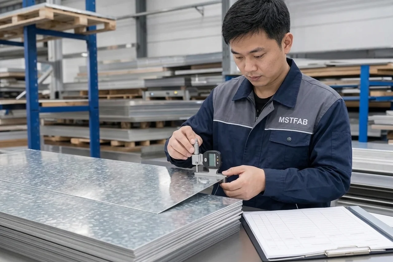
02 / Sheet Metal DFM & Structural Controls
Top 3 NEMA 12 Galvanized Junction Box Failure Modes & Sealing Fixes
Most NEMA 12 leakage failures are baked into the CAD file long before the first box reaches a dust chamber. Thin corner grinding, un-stiffened screw-cover spans, and taped foam gaskets fail predictably under industrial vibration and coolant mist. Below are the three core DFM upgrades MSTFAB engineers implement on galvanized NEMA 12 junction box builds.
Over-Ground Corner Welds Thinning 1.5 mm Walls and Creating Coolant Seepage Pinholes
Failure Mechanism: Conventional MIG welding on open 90° galvanized box miters leaves large weld beads and burns zinc off up to 15 mm from the corner. When grinders aggressively level the bead flush, wall thickness drops below 0.9 mm, exposing slag micro-pinholes that wick cutting oil into the terminal bay.
Engineering Solution: MSTFAB laser-cuts self-indexing corner alignment tabs holding fit-up gaps ≤ 0.15 mm, welds with low-heat pulse-TIG or CuSi3 silicon-bronze over copper chill bars (HAZ ≤ 4.0 mm), verifies zero pinholes via 100% dark-room light-box inspection, and seals seams with zinc-rich epoxy primer before coating.
Verified Outcome: Achieves leak-free, full-gauge corners with intact zinc protection and zero oil-wicking pinholes across high-volume runs.
Die-Cut Tape Butt Joints and Wide Latch Spacing Allowing Circulating Dust Ingress
Failure Mechanism: Four-piece adhesive foam strips meet at mitered lid corners where manual stretching creates 0.5–1.5 mm gap splits within months of thermal cycling. Combined with un-stiffened lids and latch spacing above 350 mm, cover bowing drops midpoint seal compression below 10%, letting conductive dust enter the box.
Engineering Solution: We replace taped strips with CNC-dispensed seamless FIPFG polyurethane gaskets featuring ≤ 0.5 mm start/stop overlap, form an 8–10 mm return-flange knife-edge gutter on the body, add 12 mm lid hems plus spot-welded stiffeners, and lock latch/screw pitch at ≤ 250 mm for uniform 25–35% compression.
Verified Outcome: Maintains continuous 360-degree compression pressure around all corners and passes in-house IP54/IP55 splash and dust-seal audits.
Direct Conduit Wrench Torque Distorting Unsupported 1.5 mm Junction Box Sidewalls
Failure Mechanism: Field installers tightening M32 or 1-inch rigid metal conduit locknuts directly onto flat 1.5 mm galvanized sidewalls often oil-can or warp the panel adjacent to the door gutter. That localized wall distortion twists the sealing flange out of plane, breaking NEMA 12 gasket contact near the bottom corners.
Engineering Solution: MSTFAB isolates cable-entry mechanical loads by integrating a 2.0 mm SGCC removable bottom gland plate sealed with a 3.0 mm closed-cell neoprene perimeter gasket and M5 PEM hardware—or by adding internal 2.0 mm welded reinforcement doubler plates behind fixed heavy-conduit zones.
Verified Outcome: Protects door-gutter coplanarity under heavy armored cable installation while allowing offline conduit punching before site wiring.
Manufacturing Scope Boundary: NEMA 12 Design Envelope vs. Independent UL 50 / UL 50E Listing Ownership: Contract buyers sometimes assume any factory advertising 'NEMA 12 galvanized junction boxes' holds an active UL 50 or UL 50E listing covering custom sizes. In practice, UL listings apply to specific frozen SKU families or listed panel shops, not arbitrary one-off OEM custom geometries. — Engineering Fix: MSTFAB is certified to ISO 9001:2015, IATF 16949:2016, and ISO 14001:2015 and does not hold UL 50/50E listing itself. We build empty custom NEMA 12-style mechanical junction box shells to your STEP/PDF drawings, supplying EN 10204 3.1 certs and IP54/IP55 witness data for your UL submittal. MSTFAB manufactures custom sheet metal parts and empty mechanical enclosure shells strictly to your 3D STEP and 2D PDF drawings.


03 / Representative Engineering Scenario & Process Control
Case Study: 1.5 mm SGCC Z275 NEMA 12-Style Junction Boxes for CNC Machine Tool Builders
Project Profile: Batch: 800 units/release | Body/Lid: 1.5 mm SGCC Z275; Gland Plate: 2.0 mm SGCC | Finish: 80 µm RAL 7035 Epoxy-Polyester + FIPFG Seal
OEM Engineering Challenge: A North American CNC machining-center OEM suffered recurring coolant-mist ingress inside 400 × 300 × 150 mm spindle-side junction boxes mounted near cutting zones. Their previous supplier used flat 1.5 mm lids with two widely spaced 320 mm latches and hand-applied neoprene tape corners; emulsified coolant seeped through butt-joint gaps and corroded over-ground MIG-welded bottom corners within nine months, forcing expensive field harness replacements and threatening their UL 508A machine audit.
MSTFAB Manufacturing Solution: MSTFAB re-engineered the mechanical shell around a NEMA 250 Type 12 envelope without changing external mounting footprints. We added laser-tabbed interlocking corners welded with low-heat CuSi3 bronze (HAZ 3.2 mm), formed a 9 mm return-flange knife-edge body gutter, integrated an internal lid stiffener with four captive M5 clamps pitched at 210 mm, and dispensed a continuous FIPFG polyurethane gasket targeting 30% compression. All shells received Cr-free zirconium conversion, zinc-rich seam primer, 80 µm oil-resistant RAL 7035 epoxy-polyester coating, and a 2.0 mm gasketed removable bottom gland plate.
- Zero Coolant Ingress Claims: Seamless FIPFG polyurethane sealing and 210 mm clamp spacing held uniform 30% compression, eliminating field coolant-mist seepage across 1,600 installed CNC machines over 14 months.
- 3.2 mm Maximum Weld HAZ: Laser-tabbed self-fixturing corners and CuSi3 bronze welding kept zinc heat-affected zones ≤ 3.2 mm with 100% light-box leak pass rates prior to coating.
- 100% Offline Gland Prep: Adding the 2.0 mm removable neoprene-gasketed bottom gland plate eliminated sidewall conduit distortion and cut electrical harness installation time by 22% on the line.
- 96-Hour Salt-Spray Pass: Zirconium pretreatment, zinc-rich weld-seam repair, and 80 µm epoxy-polyester topcoat passed 96-hour ASTM B117 witness testing with zero edge blistering or under-film creep.
Every production lot is archived with locked CNC laser nests, press-brake bend programs, weld fixture setups, and signed golden samples to guarantee identical repeatability across multi-year reorders.
04 / Quality Verification, Traceability & Surface Finishing
4-Stage Manufacturing Workflow, Surface Treatment & Metrology Control
To maintain Cpk ≥ 1.33 on critical-to-quality (CTQ) dimensions from prototype through series production, MSTFAB executes a closed-loop four-stage fabrication protocol:
Step 01 — Sealing-Path & Structural DFM Review: MSTFAB reviews your 3D STEP and 2D PDF drawings specifically for NEMA 12 sealing risks: verifying gutter throat depth (8–10 mm), latch spacing (≤ 250 mm), cover span stiffness, conduit reinforcement, sub-panel standoff clearances, and laser-tab corner geometry before releasing flat-pattern bend files.
Step 02 — Coil Verification, Laser Blanking & Gutter Forming: Incoming 1.5–2.0 mm SGCC Z180–Z275 coils pass micrometer and XRF zinc-mass IQC checks. High-pressure nitrogen fiber lasers cut burr-free blanks with self-fixturing corner tabs, and CNC press brakes form crisp double-return 2.5 mm knife-edge gutters and 12 mm cover hems.
Step 03 — Low-HAZ Corner Welding & Light-Box Leak Check: Copper chill-bar fixtures clamp box miters to ≤ 0.15 mm gap for pulse-TIG or CuSi3 silicon-bronze seam welding, preserving surrounding zinc protection. Smoothly dressed weldments undergo 100% internal dark-room light-box pinhole inspection and internal sub-panel PEM standoff torque-out audits.
Step 04 — Oil-Resistant Coating, FIPFG Dispensing & Witness QC: Shells receive Cr-free conversion, zinc-rich seam primer, silicone grounding-stud masking, and 70–90 µm RAL 7035 epoxy-polyester powder coat. CNC gantries dispense seamless FIPFG polyurethane gaskets on cured lids before CMM FAI, ≤ 0.05 Ω ground testing, IP54/IP55 splash checks, and VCI export crating.
All raw sheets (SPCC, SGCC, SECC, SUS304/316L, Al 5052-H32/6061-T6) are verified via optical emission spectrometry (OES) or XRF upon arrival and linked by barcode to your purchase order.
Prior to export crating in ISPM-15 fumigated plywood boxes, our quality lab conducts ballooned dimensional FAI checks, dry-film thickness (DFT) mapping, ASTM D3359 cross-hatch adhesion testing, and ground-continuity verification.
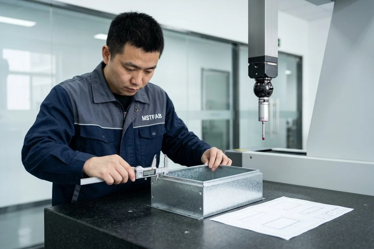

05 / 8-Point OEM RFQ Checklist & Topic Cluster Hub
OEM Engineering RFQ Checklist & Connected Fabrication Hubs
Include these eight drawing and specification controls in your RFQ package so our engineering team can lock down tooling, material traceability, and inspection fixtures on day one:
- RFQ Requirement 01Specify enclosure material and zinc mass (e.g., 1.5 mm or 2.0 mm SGCC DX51D+Z180/Z275) along with EN 10204 3.1 mill heat traceability and removable sub-panel gauge.
- RFQ Requirement 02Define the door sealing geometry: 90° inward return-flange knife-edge gutter dimensions, gasket chemistry (FIPFG polyurethane vs. vulcanized closed-cell EPDM), and 25–35% compression target.
- RFQ Requirement 03Indicate latch hardware style (quarter-turn oil-tight cam latch, padlockable handle, or captive M5 clamp screws) and enforce maximum center-to-center latch spacing (≤ 250 mm).
- RFQ Requirement 04Call out corner weldment standards: continuous CuSi3 or pulse-TIG exterior seam weld dressed flush without thinning wall gauge below 90%, plus 100% light-box leak testing.
- RFQ Requirement 05Specify whether bottom or side cable entries require a bolted, neoprene-gasketed removable gland plate (recommended 2.0 mm SGCC) or fixed CNC laser-cut conduit apertures.
- RFQ Requirement 06Detail coating system for industrial oil/coolant resistance: zirconium Cr-free pretreatment, zinc-rich weld-seam primer, RAL 7035 epoxy-polyester powder (70–90 µm DFT), and ASTM D3359 5B adhesion.
- RFQ Requirement 07Mark internal M6 grounding studs, sub-panel standoffs, and gasket seating flanges requiring high-temp silicone masking, plus ≤ 0.05 Ω protective earth continuity verification.
- RFQ Requirement 08Confirm validation deliverables: CMM FAI dimensional report, Fujifilm Prescale gasket-compression mapping, in-house IP54/IP55 water-spray witness report, and ISPM-15 export pallet packaging.
Explore Connected Sheet Metal Fabrication Services & Enclosure Hubs
06 / OEM Buyer & Engineer FAQ
NEMA 12 Galvanized Steel Junction Box Engineering FAQs
What is the difference between a NEMA 12 galvanized junction box and a NEMA 4 or 4X box?
NEMA 250 Type 12 enclosures are engineered for indoor industrial service to block circulating dust, falling dirt, lint, and dripping non-corrosive liquids such as petroleum lubricants or synthetic CNC coolants (roughly aligned with IEC IP54/IP55). Unlike NEMA 4 or 4X, NEMA 12 boxes are not designed for direct pressurized hose-down streams, outdoor sleet/ice, or severe marine salt-spray immersion. For indoor plant floors, powder-coated 1.5–2.0 mm SGCC Z180–Z275 steel delivers far greater stiffness and 45–55% lower cost than NEMA 4X SUS316L stainless while still providing sacrificial zinc defense around conduit entries.
Why is FIPFG polyurethane superior to stick-on foam tape for NEMA 12 junction boxes?
Hand-applied neoprene or EPDM foam tape must be miter-cut or butt-joined at all four corners of a junction box cover. Under factory temperature swings and enclosure vibration, those adhesive butt joints shrink and open tiny 0.5–1.5 mm channels that pull oil mist and conductive dust directly inside. By contrast, CNC-dispensed Formed-In-Place Foam Gasket (FIPFG) polyurethane cures seamlessly right inside the galvanized lid lip with ≤ 0.5 mm start/stop blend height, delivering closed-cell rebound recovery and uniform 25–35% compression around every corner without adhesive peel.
How do you keep welded corners on galvanized NEMA 12 boxes from rusting first?
Arc welding vaporizes zinc near the seam, which is why poorly built galvanized boxes always bleed red rust at the corners. MSTFAB controls this in three ways: laser-cutting self-indexing corner tabs so weld gaps stay ≤ 0.15 mm, joining with low-heat pulse-TIG or CuSi3 silicon-bronze over copper chill bars (holding the heat-affected zone under 4.0 mm), and immediately applying a high-zinc epoxy weld-seam primer after light-box leak verification and flush dressing. Overcoated with 70–90 µm epoxy-polyester powder, the corners match flat-panel 72–96 hour ASTM B117 salt-spray endurance.
Does MSTFAB supply UL 50 or UL 50E listed NEMA 12 junction boxes?
No—MSTFAB is an ISO 9001:2015, IATF 16949:2016, and ISO 14001:2015 certified contract sheet metal manufacturer, not a UL 50/50E listed catalog brand. We fabricate custom empty NEMA 12-style mechanical junction box shells strictly to OEM 3D STEP and 2D PDF drawings. To support your own UL 508A panel shop or third-party UL 50E enclosure qualification, we provide full EN 10204 3.1 galvanized coil certificates, powder-coat adhesion and salt-spray records, dimensional CMM FAI reports, and in-house IP54/IP55 water-spray and gasket-compression witness documentation.
Should our NEMA 12 junction box use a removable bottom gland plate or pre-cut conduit holes?
If your conduit layout is frozen for a dedicated machine cable harness, fixed nitrogen-laser-cut gland openings minimize gasketed joints and cost slightly less. However, if your field wiring varies by regional voltage or uses heavy armored cables, a 2.0 mm SGCC removable bottom gland plate sealed over a 3.0 mm closed-cell neoprene gasket is strongly preferred. It lets technicians punch custom conduit patterns offline without dropping metal shavings into live terminal blocks, and the thicker plate prevents heavy locknut wrenching from warping the main box shell.
International Standards & Engineering References
- ISO 2768-1 / 2768-2 — General Linear, Angular and Geometrical Tolerances for Sheet Metal Fabrication
- IEC 60529 / NEMA 250 — Degrees of Protection Provided by Enclosures (IP Code & Environmental Sealing)
- ISO 9001:2015 & IATF 16949:2016 — Quality Management Systems & Production Part Approval Process (PPAP)
Ready to Quote Your Custom Sheet Metal Enclosure or Fabrication Project?
Upload your 3D STEP models and 2D PDF drawings. MSTFAB will review your tolerances, material specs, and DFM details to deliver a transparent factory quote within 24 hours.
Request Your 24-Hour DFM & Custom Quote →
Direct engineering desk: caroline@mstfab.com | ISO 9001 & IATF 16949 Certified Factory in Guangzhou, China
 WeChat Contact
 WhatsApp Me Directly