
Sheet metal punching creates openings with a punch and die; bending forms the blank into flanges, brackets or enclosure sections. When both operations are required, a correctly punched flat pattern is only an intermediate result. The order should define which hole positions, surfaces and mating features must be accepted after forming and any specified finishing.
How do punching and bending work together?
A possible route is material verification, blank preparation and punching, edge treatment where specified, forming, then the remaining hardware, finishing and inspection operations. The actual sequence depends on the part. Features made with special forming tools may also affect handling and later tool access, so a route should be reviewed rather than copied from a generic checklist.
Repeated holes, slots or louvers can make punching worth evaluating, but the choice is not determined by order quantity alone. Available tooling, material, hole pattern, revision frequency and setup requirements also matter. Laser cutting may be an alternative for particular profiles; neither process automatically satisfies the requirements of the finished bent component. Special punching tools can create formed features, but that does not mean any manufacturer has every tool or can form every geometry.
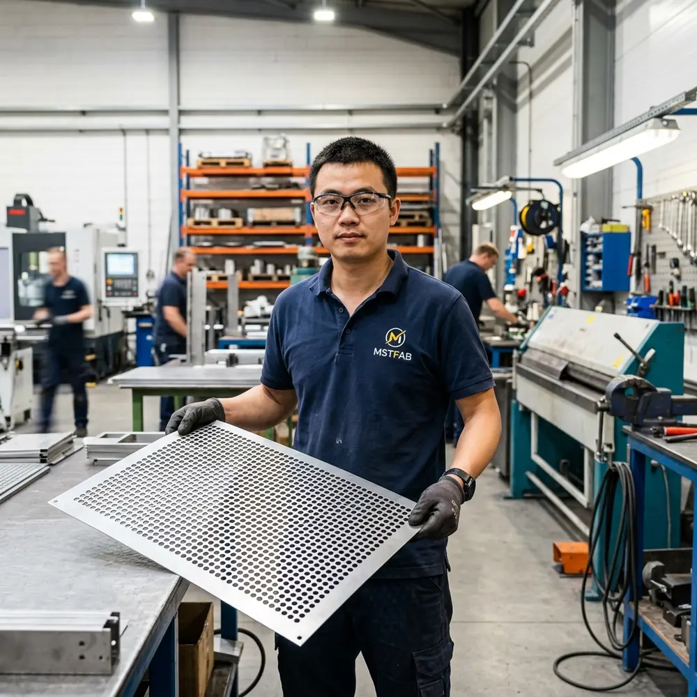
Five checks between the punched blank and the bent part
| Feature | Question before forming | Acceptance evidence to agree |
|---|---|---|
| Hole near a bend | Could the forming zone or tooling distort the opening? Is relocation or a different process needed? | Hole size and position on the formed part, using drawing-defined references. |
| Dense perforation | Could the punching sequence and resulting distortion affect support, gauging or panel shape? | Specified flatness or profile at the agreed stage and support condition. |
| Burr and visible face | Which side may have the burr, and which surfaces contact tooling or remain visible? | Defined edge condition and cosmetic surfaces, not simply “clean finish.” |
| Louver or formed feature | Will the feature interfere with a later bend, fixture, tool or mating component? | Required orientation, envelope and access checks on the formed component. |
| Hardware and finish | When are inserts installed and surfaces finished, and which interfaces need protection? | Delivered interface dimensions and any masking or fit check specified by the buyer. |
Why can holes change during bending?
A nearby opening can enter the region affected by forming. Its shape or its relationship to a mating feature may then differ from the flat blank. There is no single hole-to-bend distance that is valid for every material, thickness, radius and tooling arrangement. Identify the critical feature and ask for a part-specific review; do not turn an approximate design rule into a guaranteed acceptance limit.
Repeated punching can also introduce sheet distortion. This is separate from bend-angle control: a successful angle check alone does not establish panel flatness or hole alignment. Decide which characteristics matter and at which manufacturing stage they will be measured.
Illustrative example: a perforated equipment cover has mounting holes on two flanges. The flat hole pattern may be correct while the formed flange spacing prevents assembly. The review therefore needs the finished spacing and hole relationship, not just an approved DXF. This is a hypothetical explanation, not a reported MSTFAB customer result.
What should the first-article inspection actually confirm?
Separate blank checks from formed-part and delivered-part checks. A useful inspection plan identifies the drawing revision, feature, reference system, required condition and proposed measurement method. A caliper reading alone may not establish a positional or profile requirement. Agree suitable methods for the particular feature rather than promising that one instrument can verify the whole part.
- Blank: required hole pattern, outside profile, edge condition and material identification.
- Formed component: relevant flange dimensions, angle, hole relationships, clearance and shape.
- Delivered component: any specified hardware fit, coated interfaces, cosmetic condition and packaging protection.
A fit check can support dimensional inspection when its fixture or mating component and acceptance criteria are defined. It is not a substitute for unrelated drawing requirements or final equipment validation.
What belongs in the drawing review?
Provide controlled geometry, material grade and thickness, quantity, required finish and the intended delivery scope. Highlight holes close to bends, perforated areas, formed features and interfaces whose position is important after bending. Confirm who develops the flat pattern and which released document governs when files disagree. For a broader drawing checklist, see the sheet metal bracket drawing guide.
This article addresses the handoff between two operations. Commercial capability and project feasibility belong in a drawing-specific review through the sheet metal bending service; alternative blank preparation is covered by the laser cutting service. No machine capacity, universal tolerance or tooling availability is guaranteed here.
Frequently asked questions
Should holes be punched before or after bending?
Many routes create holes in the flat blank, but the correct sequence depends on access, tooling and the required finished feature. Review holes near bends and critical interfaces before agreeing the route; do not assume one sequence works for every part.
Can a punched flat pattern prove the finished holes will align?
No. Forming can change the relationship between features. Acceptance should cover the required hole positions and mating interfaces in the formed or finished condition specified by the drawing.
Is punching always cheaper than laser cutting?
No. Tool availability, setup, geometry, material, quantity and design changes affect the comparison. Compare quotations for the same delivered scope and acceptance requirements rather than choosing by process name alone.
Request a part-specific process review
Send MSTFAB your drawings and project requirements, identifying the features that must fit after forming and finishing. Ask the quotation to state the proposed route, included operations and inspection scope. Fabricating a mechanical cover or bracket does not establish the safety, electrical continuity or certification of the final equipment.
Process background: Mate: reducing punching-related sheet distortion; TRUMPF: punching tools for forming. These references explain process considerations, not MSTFAB equipment ownership or verified production capability.
 WeChat Contact
 WhatsApp Me Directly