
What critical 10-point DFM checklist prevents manufacturing delays and tooling scrap on sheet metal bracket drawings?
A production-ready sheet metal bracket drawing must verify: (1) consistent internal bend radius matching standard tooling (r ≥ 1.0t steel, 1.5t aluminum), (2) minimum hole-to-bend clearance ≥ 2.5t + r to prevent hole ovality, (3) minimum flange height ≥ 4.0t to span the press brake V-die opening, (4) rectangular/teardrop bend reliefs (width ≥ t, depth ≥ r + t), (5) self-clinching PEM hardware centerline-to-edge clearances per manufacturer catalogs, (6) uniform grain direction callouts, (7) bend deduction / K-factor alignment, (8) clear GD&T datum schemes, (9) gusset reinforcement geometry for heavy cantilever loads, and (10) powder coat masking notes on grounding surfaces.
1. Why Sheet Metal Bracket Drawings Fail in Production
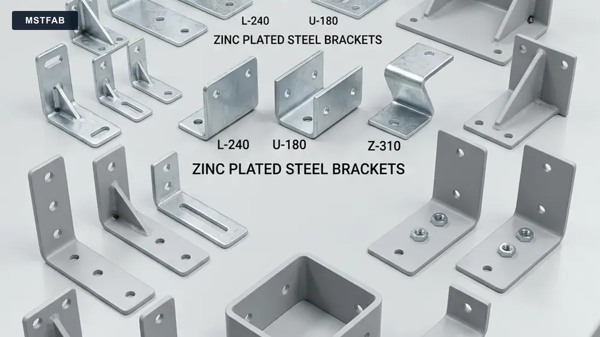
Brackets are the most ubiquitous components in mechanical engineering—connecting structural members, mounting sensors, supporting wire harnesses, and bracing electrical components. Yet, despite their apparent simplicity, sheet metal brackets account for a disproportionate share of engineering change orders (ECOs), tooling collisions, and prototype rejections.
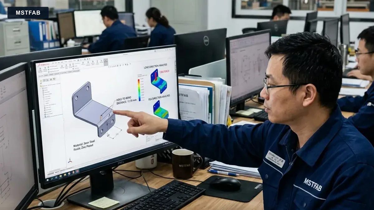
Most CAD software tools (SolidWorks, Inventor, Creo) allow designers to model geometry that is physically impossible to fabricate: zero-radius sharp inside corners, holes placed directly inside the bend deformation zone, flanges too narrow to bridge press brake dies, and clinch studs placed where hydraulic insertion tooling cannot fit. Following a systematic DFM drawing checklist bridges the gap between theoretical CAD solids and physical sheet metal realities.
2. The 10-Point Sheet Metal Bracket Drawing Checklist
Check 1: Standard Inside Bend Radius (IR)
Never leave bend radius to CAD software defaults (which often assume zero or 0.2 mm). The inside bend radius should match standard tooling punches. For cold-rolled mild steel, specify IR = 1.0t. For 5052-H32 aluminum, use 1.0t to 1.5t. For 304 stainless steel, use 1.0t to 1.5t. Keeping bend radii identical across all bends on a single bracket allows the part to be formed in a single setup without costly tool changes.
Check 2: Minimum Hole-to-Bend Distance
When sheet metal bends, material stretches. Any hole located within the bend transition zone will distort into an egg shape, rendering bolt insertion impossible. Maintain a minimum distance from the hole edge to the bend tangent line of d ≥ 2.5t + r. If holes must be positioned closer, incorporate an oval relief slot across the bend line or laser-cut the hole post-forming.
Check 3: Minimum Formed Flange Height
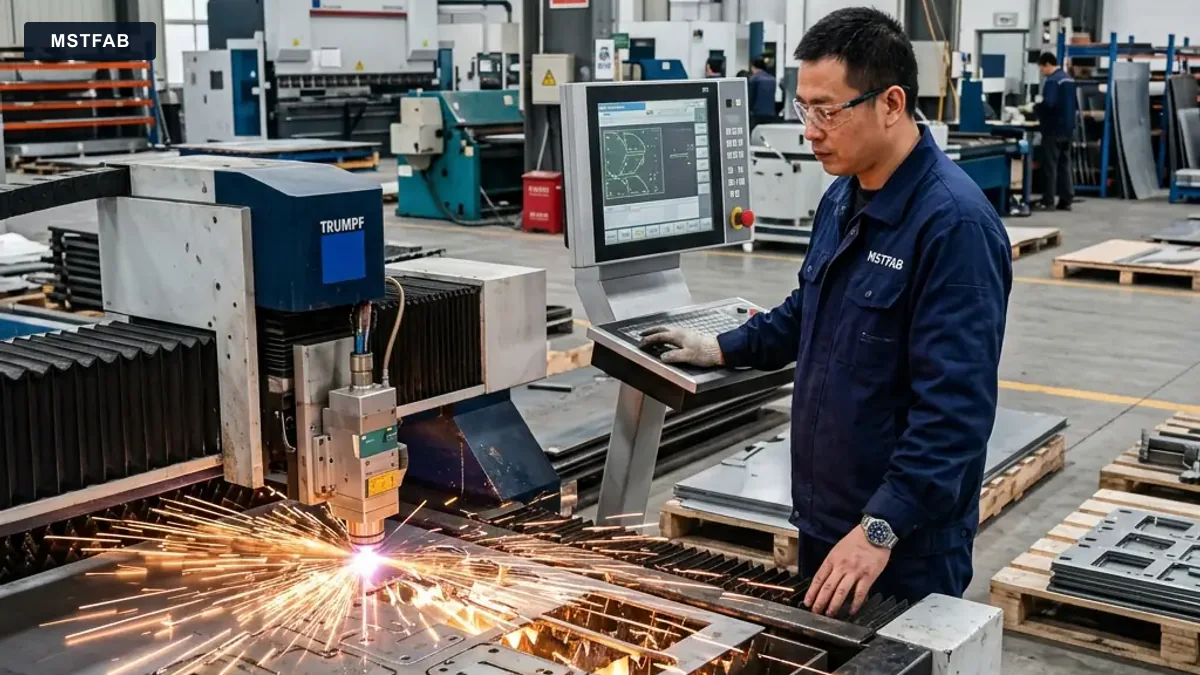
To form a flange on a standard press brake, the material must bridge across both shoulders of the bottom V-die. The rule of thumb for minimum external flange height is hmin ≥ 4.0t. Flanges shorter than this will slip into the V-groove before the punch tip can coin the bend, causing extreme angle variation and dangerous tool slippage.
Check 4: Proper Bend Relief Geometry
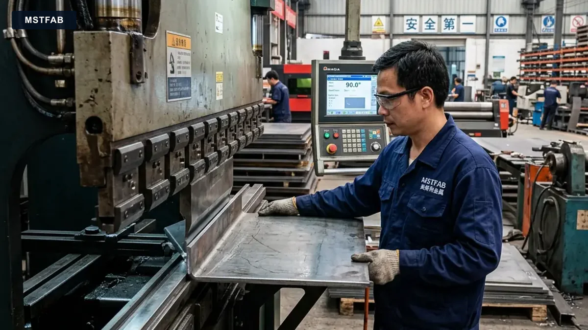
When a flange is bent adjacent to an unbent section of the sheet, the metal will tear at the corner unless a bend relief is provided. Always detail a rectangular or teardrop bend relief. The minimum relief width must equal material thickness (w ≥ 1.0t), and the relief depth must extend past the tangent line of the bend radius (depth ≥ r + t).
Check 5: Gusset & Rib Reinforcements
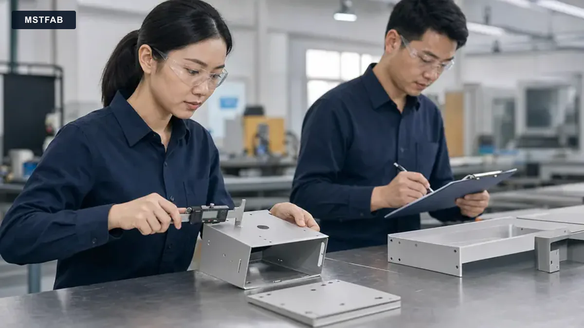
When brackets must carry heavy dynamic loads or cantilevered motors, increasing the sheet thickness across the entire bracket wastes material and adds excess weight. Instead, specify stamped triangular ribs or welded gusset plates across the 90° bend. A welded gusset increases bracket torsional and bending stiffness by over 400% without increasing base sheet thickness.
Check 6: Self-Clinching Hardware Installation Access
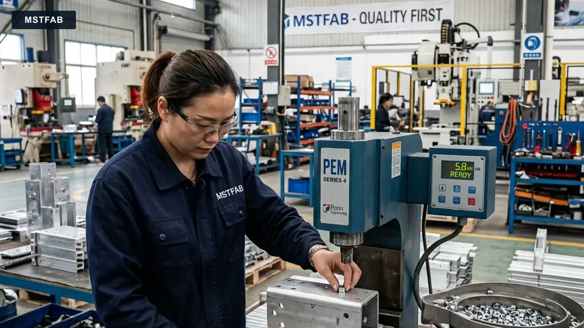
Self-clinching nuts, studs, and standoffs (PEM fasteners) require clearance for the pneumatic installation press punch and anvil tooling. Consult PEM catalog “Centerline to Edge” (C/L to Edge) minimum clearances. Furthermore, ensure there is sufficient straight clearance between the fastener hole and adjacent formed return flanges; if a flange is too close, the press tooling horn cannot reach the fastener axis.
Check 7: Powder Coating Masking & Thread Protection
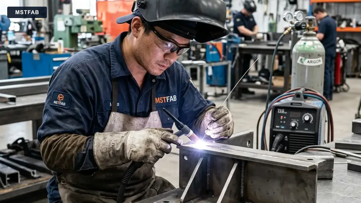
Powder coating adds 70 μm to 120 μm of cured resin to all exposed surfaces. If threaded PEM studs, grounding lugs, or tight-tolerance mounting holes are not masked, bolts will seize and electrical ground continuity will be severed. Engineering drawings must explicitly call out masking zones with circular cross-hatch symbols and notes: “MASK PRIOR TO POWDER COAT; ZERO COATING IN INTERNAL THREADS”.
Check 8: Realistic GD&T & General Tolerances
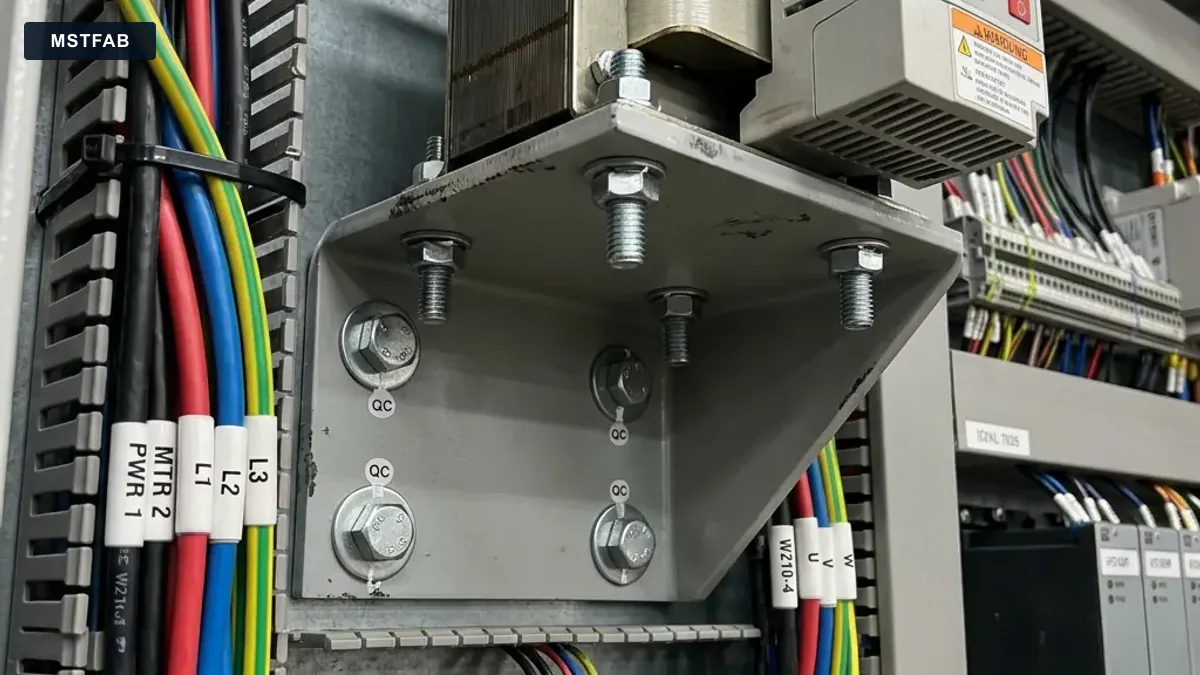
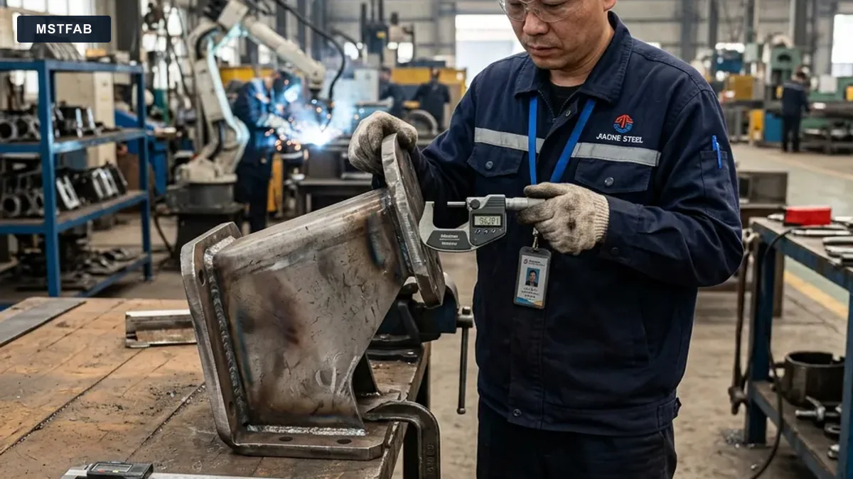
Avoid applying default title-block machine shop tolerances (±0.05 mm) to formed sheet metal dimensions. Standard sheet metal press brake forming capability is ±0.25 mm for flange heights and ±0.5° for bend angles. For critical mounting hole patterns, specify true position callouts relative to functional datums with Maximum Material Condition (MMC) modifiers.
Check 9: K-Factor & Bend Deduction Alignment
Different fabricators utilize specific K-factors based on their proprietary tooling and material supplier chemistries. Provide clean 3D CAD models (STEP/IGES) alongside 2D PDFs, but avoid hardcoding flat pattern dimensions on drawings. Allow the fabricator to unfold the 3D model using their shop-calibrated K-factors for guaranteed dimensional accuracy.
Check 10: Export Packaging & Edge Protection
Finished brackets with protruding PEM studs or delicate powder coatings will scratch and deform if bulk-packed in loose cartons. MSTFAB utilizes custom slotted carton dividers and foam interleave sheets to ensure pristine delivery.

3. Comprehensive Sheet Metal Bracket Drawing Audit Matrix
| Checklist Item | Standard DFM Rule | Common Drawing Error | Fabrication Risk If Ignored |
|---|---|---|---|
| 1. Inside Bend Radius | IR ≥ 1.0t (Steel); ≥ 1.5t (Alum/SS) | Zero inside radius on 3D CAD | Outer tensile bend cracking; die gouging |
| 2. Hole-to-Bend Spacing | Edge-to-tangent ≥ 2.5t + r | Hole placed inside bend relief line | Egg-shaped, stretched hole; bolt won’t fit |
| 3. Minimum Flange Height | hmin ≥ 4.0t | Flange too short to bridge V-die opening | Flange slips into die; severe angle error |
| 4. Bend Relief Geometry | Width ≥ 1.0t; Depth ≥ r + t | Sharp zero-width slit or missing relief | Tearing at flange transition corners |
| 5. PEM Hardware Clearances | Adhere to manufacturer C/L to edge | Stud placed directly against return flange | Insertion press tooling cannot reach fastener |
| 6. Gusset Reinforcements | Stamped rib depth ~1.5t; welded plate | Over-thickening entire sheet for localized stiffness | Tripled part weight and material waste |
| 7. Powder Coat Masking | Explicit notes & hatched areas on 2D | Relying on verbal instructions | Paint-clogged threads; loss of electrical grounding |
Get a Free DFM Review on Your Sheet Metal Bracket Drawings
Send us your 2D PDF drawings and 3D CAD models. MSTFAB engineers audit your bracket designs against tooling availability, hole-to-bend spacing, bend reliefs, and hardware clearances to guarantee rapid prototyping and zero-defect volume production.
 WeChat Contact
 WhatsApp Me Directly