
OEM EMPTY CONTROL BOX SHELL TOLERANCE GUIDE
Answer: A useful control box tolerance plan identifies functional features, establishes stable datums, assigns process-appropriate tolerances and states how critical results will be measured.
This sheet metal control box tolerance guide applies to empty shells, doors, blank mounting plates, brackets and hardware. MSTFAB does not supply PLCs, HMIs, wiring or a finished control system.

1. There is no single tolerance standard for every control box
Material, thickness, size, bend count, welding, coating and measurement method change achievable variation. A laser-cut plate and a welded cabinet should not share one blanket tolerance.
Use general tolerances for noncritical dimensions and explicit values for door cutouts, mounting patterns, hinges, latches, gasket lands and mating brackets.
| MSTFAB can control | Outside MSTFAB scope | Customer owns |
|---|---|---|
| Profiles, bends, weldments, blank plates, hardware, finish and inspection | PLCs, HMIs, wiring, programming and functional testing | Interfaces, tolerance intent, electrical clearances and system performance |
| Mechanical fit against drawings, samples or fixtures | Complete-box certification or commissioning | Ingress, EMI/EMC, safety and compliance |
Values here are RFQ references, not a universal capability guarantee. Final acceptance must be confirmed for the actual part and inspection method.

2. Start with function, datums and a controlled drawing
Ask what the feature must do. A mounting pattern locates a subpanel; a door opening positions a device; a gasket land may need flatness. Choose datums that remain stable through fabrication and inspection.

Use baseline or ordinate dimensions for related holes instead of long chains. GD&T can define position, profile, perpendicularity, parallelism or flatness more clearly than many plus/minus dimensions.
The 3D model explains shape; the controlled drawing identifies datums, tolerances, threads, welds, finish and inspection. Conflicts require clarification before production.
3. Match laser-cut tolerances to material and feature size
Fiber laser cutting accuracy depends on material, thickness, plate condition, part size, heat and feature geometry. Small holes in thick plate or narrow slots may need secondary work.
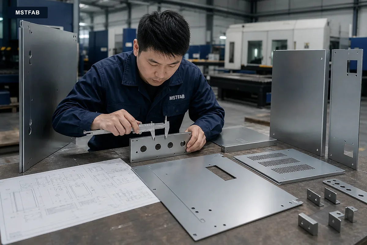
For suitable geometry, RFQ discussion may begin around +/- 0.10 to 0.20 mm for selected laser-cut features. Large panels, thick material or dense perforations may require wider values.
Hole size and position are separate requirements. Precision pins or dowels may need drilling, reaming or machining after laser cutting.

Before cutting, MSTFAB checks units, scale, contours, duplicate lines, slot width, small features and revision.
4. Control formed dimensions, angles and tolerance stack-up
CNC bending adds inside radius, tool opening, material strength, grain direction, springback and flange access. Define whether dimensions reference inside, outside or theoretical-sharp features.

A simple flange discussion may begin around +/- 0.30 to 0.50 mm and +/- 0.5 to 1 degree under suitable conditions. Multi-bend boxes and long flanges need separate review.
Several allowed bend variations can exceed assembly clearance even when each bend passes. Dimension the final functional surface from the primary datum and verify angle, flange height, envelope and holes after forming.
5. Treat welding and flatness as assembly characteristics
Welding adds heat and restraint. Panels can bow, frames can pull diagonally and door openings can change. Fixtures, weld sequence and intermediate checks reduce distortion.

Large welded shells may begin discussion around +/- 1.0 to 2.0 mm depending on size, material, frame and weld length. Tighter local interfaces need their own process.
Flatness must identify surface, support condition and zone. A clamped door is not the same as a free-state door; a gasket land may need local control.
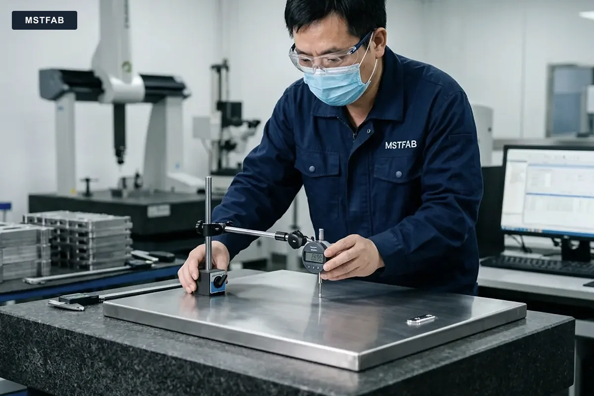
Door gap, hinge alignment, latch engagement and panel fit can be more useful than unrealistic whole-surface flatness.
6. Include hardware and coating in the dimensional plan
PEM nuts, studs, rivet nuts, hinges and latches need thread, orientation, installation side and edge distance. Inspect presence, position, thread and seating.
Powder coating adds thickness. Threads, ground zones, bearing surfaces and tight fits may need masking. Allow coating on mating parts.

State whether each controlled dimension applies before or after finish.
- Hardware type and thread
- Installation side and orientation
- Masked holes and ground zones
- Coating-sensitive clearances
- Door and latch fit after coating
- Cosmetic surface acceptance
7. Select an inspection method that fits the characteristic
Use the method that fits the feature: digital caliper, height gauge, pin gauge, thread gauge, angle gauge, fixture or CMM. Access and measurement uncertainty matter.
Define free-state or restrained support, remove burrs, record instrument resolution and calibration, and agree rounding near a limit. Controlled setup prevents two inspectors from producing two answers.

| Characteristic | Possible method | Evidence |
|---|---|---|
| Overall size and flange | Caliper, height gauge or fixture | Value and revision |
| Hole size and thread | Pin or thread gauge | Pass/fail or value |
| Position or profile | Height gauge, fixture or CMM | Datum report |
| Angle, flatness and fit | Gauge, granite plate or trial fit | Record or sample |
First Article Inspection identifies part, revision, material, characteristic, nominal, tolerance, method and result. For repeat work, define setup, every-part and sampled checks.
8. Build the RFQ around evidence, not the tightest number
Tighter tolerances increase setup, fixtures, secondary work, inspection and scrap risk. They should protect function, not decorate the drawing.
| RFQ item | What to provide | Why it matters |
|---|---|---|
| Design | STEP, drawings and revision | No mixed geometry |
| Function | Datums and critical features | Precision where needed |
| Process | Material, welds, hardware and finish | Realistic review |
| Acceptance | Method, report and sampling | Comparable evidence |
When a tolerance needs adjustment, record the exact characteristic, current value, proposed value, manufacturing reason and inspection method. Do not quietly widen a general note or change the model without updating the drawing. The customer should approve the deviation before production, and the approved value should appear in the released revision or a controlled concession. This keeps purchasing, production and inspection aligned and prevents an accepted prototype from becoming an undocumented standard for later batches.
Provide quantities, critical dimensions, samples or mating parts, First Article needs and destination. MSTFAB can flag unclear features, secondary machining or practical adjustments.
Frequently asked questions
What tolerance can MSTFAB hold?
It depends on material, size, feature, forming, welding and finish. Critical features are reviewed per drawing.
Should every dimension be tight?
No. Tight values protect fit, sealing or alignment; other dimensions can use practical general tolerances.
Can cut and bent features use one tolerance?
Not automatically. Forming adds tooling, radius and springback variation.
Does MSTFAB inspect a complete control system?
No. MSTFAB inspects the empty shell and agreed mechanical features, not electronics or system performance.
Can inspection reports be supplied?
Yes, when agreed before quotation. Define characteristics, format, sampling and any CMM or First Article requirement.
Send the controlled tolerance package
Share the model, drawings, datums, critical features, material, finish, quantity and inspection requirements.
 WeChat Contact
 WhatsApp Me Directly