
What should an OEM specify for EMI shielding and grounding?
Specify the applicable compliance route, frequency range, shielding target, bonding interfaces, cable-entry treatment and test configuration. There is no universal dB value, bonding resistance or conductor size for every outdoor telecom cabinet. The finished equipment and installation determine the requirement; the metal fabricator turns the approved mechanical details into repeatable parts.

Start with the responsibility boundary
| Work item | Typical owner | Controlled output |
|---|---|---|
| Applicable EMC and radio requirements | Equipment OEM and compliance engineer | Compliance plan, market list and test requirements. |
| Shielding and bonding architecture | OEM electrical or EMC engineer | Approved drawings, component specifications and acceptance criteria. |
| Mechanical implementation | Sheet metal fabricator | Seams, gasket lands, masked contact areas, studs, brackets and openings to drawing. |
| Installed cables, filters, glands and electronics | OEM or system integrator | Final bill of materials and assembled test configuration. |
| Compliance testing and approval | OEM and qualified laboratory or conformity route | Report tied to the tested configuration and applicable requirements. |
Where shielding continuity usually breaks
Design the gasket land as a mechanical interface
The OEM should specify the conductive gasket type, compression range, corner treatment and compatible surface. The fabricator then controls flange flatness, door stiffness, fastener spacing, latch position and the geometry that lets the gasket work.

- Show the gasket path and termination detail on the released drawing.
- Define acceptable gaps, steps, weld dressing and flange distortion.
- Identify whether environmental sealing and EMI shielding use one gasket or separate systems.
- Control latch hardware and door stiffness so compression is repeatable.
- Treat a gasket substitution as an engineering change.
Control coating and conductive contact areas
Powder coating protects and finishes the cabinet, but it can interrupt electrical continuity. The drawing should identify masked lands, grounding studs, connector faces and other contact areas. It should also define how those exposed areas are protected from corrosion without defeating the electrical function.

Grounding and bonding are related, but not interchangeable
Protective earthing addresses safety. Equipotential bonding and high-frequency bonding support electrical continuity and EMC behavior. A cabinet may need all of them, but the conductor, path and acceptance criteria come from the equipment design and applicable standards.
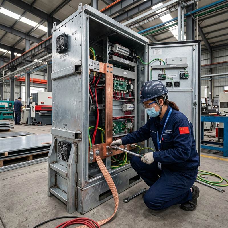
Mechanical drawings should locate grounding or bonding studs, identify thread and installation method, reserve coating-free contact areas where specified and show any flexible bonds across hinges or removable panels. Do not copy one resistance value or cable size from another cabinet and call the design finished.
Treat cable entry, filters and ventilation as one system
Cable shields, glands, connector panels, feedthrough filters, honeycomb vents, fans and heat exchangers can all change the shielding boundary. Their cutouts and mounting surfaces should be based on selected components rather than generic catalog dimensions.
Thermal and EMC decisions can pull in opposite directions: a larger opening improves airflow while making shielding more difficult. Freeze the actual component envelope, service access and replacement method before releasing the cabinet drawing. For adjacent thermal decisions, use the outdoor telecom cooling hardware interface checklist.
Set the target from the compliance plan
The finished product’s intended market and radio functions determine which rules and standards apply. FCC Part 15, where applicable, governs radio-frequency devices and uses defined equipment-authorization and measurement procedures. IEC 61000 documents cover EMC topics and mitigation guidance, but the relevant product or product-family standard may take precedence.
Use the FCC equipment authorization procedures and the IEC TR 61000-5-1 overview as starting references. Confirm the current applicable editions and test plan with the OEM’s compliance engineer or laboratory.
| Requirement to freeze | Why it matters | Useful evidence |
|---|---|---|
| Frequency range and shielding target | Gasket, seams and apertures behave differently across frequency. | Approved EMC requirement or test plan. |
| Complete test configuration | Doors, vents, glands, cables and installed equipment affect results. | Configuration list, photographs and report identifiers. |
| Mechanical acceptance criteria | Production needs measurable controls before system testing. | Gap, flatness, mask, stud and hardware inspection records. |
| Change triggers | A small substitution can invalidate the evidence baseline. | Written approval record and revised test assessment. |
Test the approved configuration, then control changes
Pre-compliance checks can find obvious discontinuities, but final evidence should follow the buyer-approved method and configuration. Record the cabinet revision, gasket, closures, vents, glands, filters, cables and installed equipment used during testing.
After approval, changes to seams, door geometry, coating masks, gasket, hardware, entries, vents or bonding parts should enter engineering change control. “Same size” is not the same as “same EMC behavior.”
Outdoor telecom cabinet EMC RFQ checklist
- 2D and 3D files with one released revision.
- Applicable markets, product standards and compliance owner.
- Frequency range, shielding target and test configuration.
- Conductive gasket specification and compression requirements.
- Masked contact areas and corrosion-protection method.
- Grounding studs, busbar mounts and flexible-bond interfaces.
- Selected glands, connectors, filters, vents and thermal hardware.
- Critical mechanical dimensions and first-article records.
- Approved substitution and retest rules.

Frequently asked questions
What shielding effectiveness does an outdoor telecom cabinet need?
There is no universal value. The OEM or EMC engineer should derive the target and frequency range from the equipment, intended market, radio environment and applicable test plan.
Does powder coating reduce electrical continuity?
Conventional powder coating is insulating. Drawings should identify conductive mating surfaces and the approved masking or finish strategy while also addressing corrosion protection.
Can an empty cabinet shell be FCC or EMC certified?
An empty build-to-print shell does not by itself establish compliance for the finished electronic equipment. The responsible OEM controls the final configuration, testing and authorization route.
What should a fabricator inspect before shipment?
Typical mechanical checks include seam and flange geometry, door gap, gasket land, mask dimensions, stud location, opening size, selected hardware and the controlled drawing revision.
For commercial fabrication scope, review 5G telecom enclosure solutions and outdoor telecom enclosure fabrication.
Review the mechanical EMC interfaces
Send the cabinet drawing, selected gasket and hardware, compliance inputs and required first-article records. MSTFAB will review the build-to-print metalwork.
 WeChat Contact
 WhatsApp Me Directly