
Last Reviewed: October 2026
For: OEM Procurement, Mechanical Engineers and Industrial Equipment Manufacturers
Scope: Drawing-based equipment trays, support trays, drainage trays, module trays and fabricated sheet metal tray assemblies.
Quick Answer
A custom sheet metal tray is not simply a flat plate with four bent edges.
For industrial OEM equipment, the finished tray may need to:
support components + fit a chassis or frame + maintain mounting-hole alignment + manage drainage + resist distortion + accept hardware + survive finishing and transport.
For procurement, the important requirements are:
material + thickness + flange geometry + mounting datums + support points + drain features + hardware + finish + inspection condition.
The buyer should define the required equipment loads and functional requirements. The fabricator’s job is to manufacture the approved metal geometry consistently.
A tray can look perfectly respectable on a table and still become very unpopular when the module does not fit.
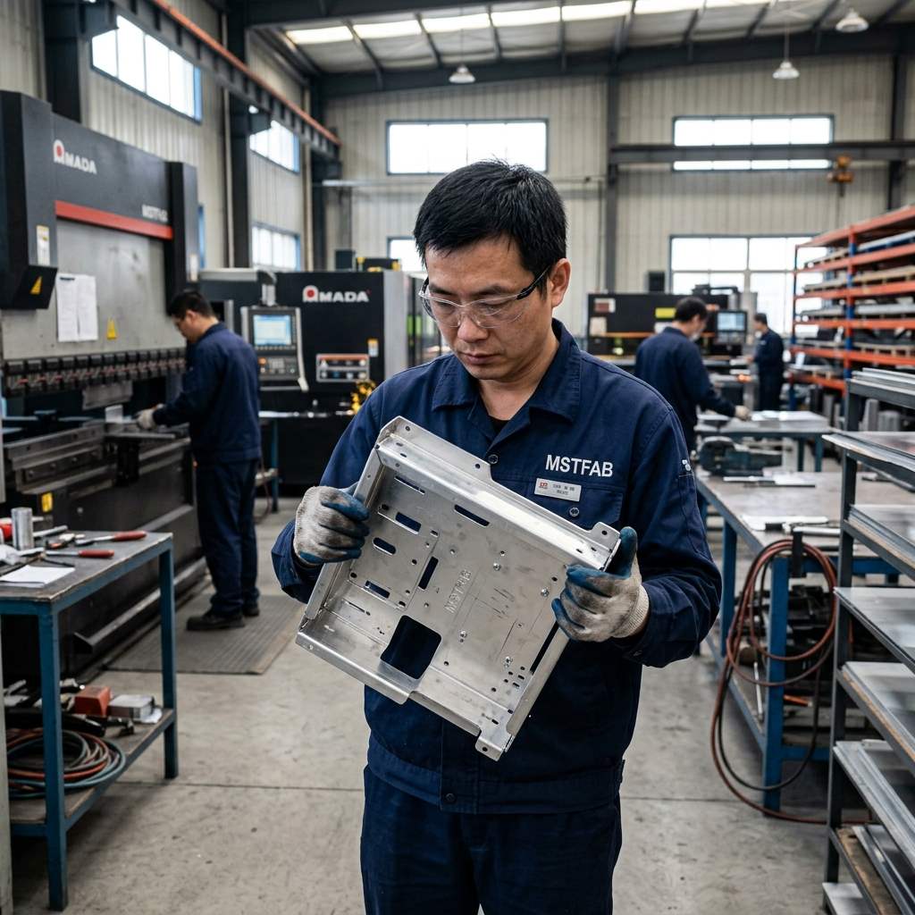
1. Define What the Tray Actually Does
Not every industrial tray has the same function. Typical OEM applications include:
- equipment module trays;
- battery or power-module support trays;
- cabinet internal trays;
- electronic equipment trays;
- cable-management trays;
- drainage or drip trays;
- removable service trays;
- rack or chassis trays.
Before requesting a quote, tell the supplier which function matters. A tray designed mainly to hold a module has different priorities from one designed to collect and route liquid. The outline may look similar. The acceptance criteria are not.
2. Start With the Support Interface
For a load-supporting tray, identify where the tray actually contacts or attaches to the equipment. That may include: chassis rails, cabinet studs, frame brackets, bolt patterns, support tabs, slide interfaces, or welded supports.
| Tray Feature | Why It Matters |
|---|---|
| Main mounting-hole pattern | Equipment installation |
| Support flange height | Load/support interface |
| Module mounting holes | Component fit |
| Rail spacing | Tray insertion |
| Base flatness where required | Component seating |
| Welded bracket location | Finished support geometry |
The outside dimensions may be easy to measure. The real question is whether the buyer’s equipment lands where it should.
3. Bends Do More Than Create the Walls
Bent flanges can provide: stiffness, component containment, mounting faces, edge protection, alignment, and support. That means flange height, bend angle and return geometry can be functional dimensions.
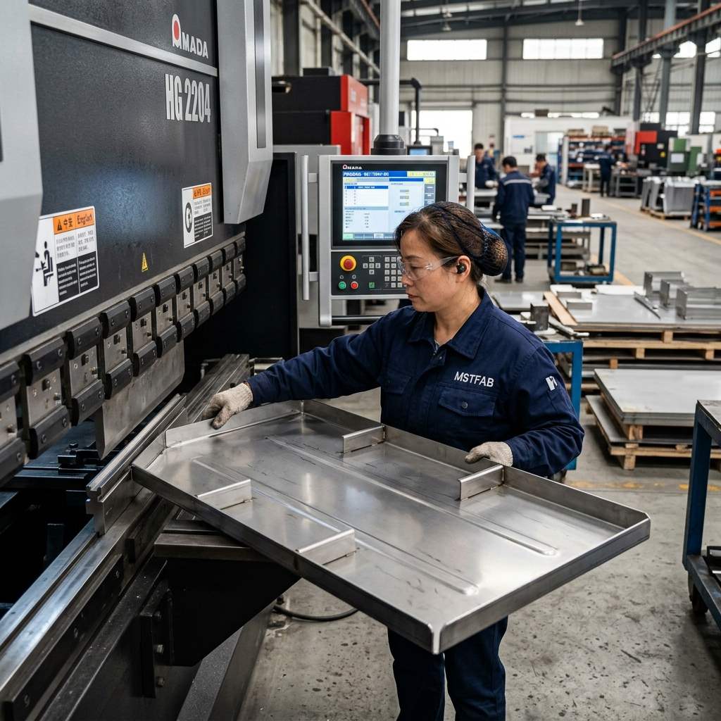
For an industrial tray, ask: Which flange actually supports or locates another part? Those dimensions deserve more attention than a non-functional edge. A bend is not decoration. Sometimes it is the structure.
4. Load Requirements Should Come From the OEM
If the tray supports batteries, power modules, pumps, electronic assemblies, tooling, or mechanical components, the OEM should define the relevant load and support requirements. The supplier can review manufacturability, but MSTFAB should not independently decide what load a finished OEM system must safely carry.
A useful drawing may specify: component mass, support locations, allowed deflection where relevant, mounting points, load direction, and approved reinforcement geometry. Then the tray can be manufactured against a real requirement instead of: —Make it strong.”Strong is popular. It is not a dimension.
5. Do Not Assume Thicker Sheet Is Always the Best Answer
When a tray needs more stiffness, increasing material thickness is one option, but not the only one. Depending on the buyer-approved design, stiffness may also come from deeper flanges, return bends, formed ribs, reinforcement channels, brackets, or welded supports.
Thicker material also changes weight, cost, forming force, and handling. Supplier DFM can identify manufacturing options, but Engineering should approve any design change before it becomes production geometry.
6. Drainage Needs a Real Flow Path
For a drainage or drip tray, adding one drain hole does not automatically create good drainage. The buyer should define: liquid collection area, drain location, drain-hole or fitting geometry, required slope, low points, containment edges, and outlet interface.
Then check whether the formed tray actually creates the intended path. Bending or welding can create a local high/low area that was less obvious in the flat CAD model. The practical question is: Does the finished tray drain where the drawing says it should?
7. Drain Holes Should Be Reviewed Before Bending and Finishing
Drain features can fail in several boring ways: too close to a bend, distorted during forming, partially blocked by hardware, positioned above the real low point, reduced by coating, or inaccessible after assembly.
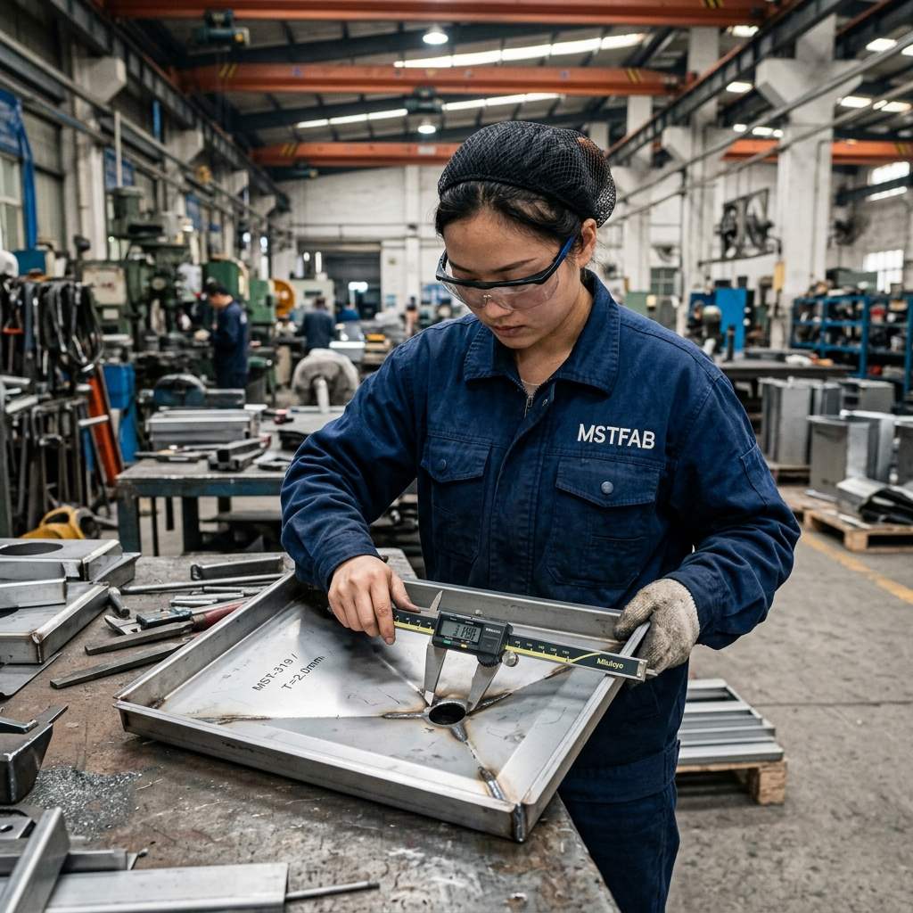
If drainage is functional, identify the drain feature as an inspection point. The supplier should review it in the finished tray condition, not only the flat pattern.
8. Hole Patterns Should Follow Functional Datums
A tray may contain dozens of module mounting holes, PEM locations, slots, cable openings, or drainage holes. Not all should be dimensioned from random plate edges. Use meaningful functional references where assembly requires them (e.g., Datum A ”tray base, Datum B ”rear locating flange, Datum C ”side locating flange).
9. Hardware Orientation Matters More Than It Looks
Industrial trays frequently use PEM nuts, rivet nuts, studs, threaded inserts, standoffs, or welded nuts. The RFQ should identify: part number + thread + quantity + position + installation face.
The last one matters. A PEM nut installed perfectly on the wrong side is still perfectly wrong. Before shipment, verify the hardware in the condition the buyer actually receives.
10. Welding Can Change Tray Flatness
Some trays require welded corner joints, reinforcement channels, brackets, supports, or drain fittings. Heat can influence base flatness, flange relationship, hole position, and mounting geometry. If welding is part of the tray, the buyer should identify which dimensions matter after welding.
11. Flatness Should Match the Equipment Need
Not every tray needs an extreme full-surface flatness requirement. Ask first: What actually sits on this surface? Define functional areas and inspection conditions where necessary. —Perfectly flat”is easy to type. The quotation will certainly notice.
12. Powder Coating and Finish Can Affect Function
Finish should be treated as part of the manufacturing specification. Coating can affect threads, drain holes, locating surfaces, hardware, tight slots, and electrical contact areas. For the RFQ, specify: finish type, color, masking, protected threads, and surfaces that must remain uncoated.
13. Keep Electrical Functions Buyer-Defined
A tray may contain grounding studs or uncoated contact points. MSTFAB can manufacture those mechanical features according to the drawing. But the OEM remains responsible for defining electrical bonding architecture, required continuity, grounding strategy, and certification. MSTFAB manufactures the sheet metal around it.
14. First Article Should Be Loaded or Fit-Checked Where Useful
For a support tray, dimensional inspection is useful. A real assembly check can be even more useful. Where practical, verify: tray installation, module mounting, rail fit, hardware engagement, flange clearance, drainage path, and access for assembly.
Tray vs Base Plate vs Chassis vs Panel
| Part | Main Function | Main Buyer Concern |
|---|---|---|
| Tray | Holds, supports, contains or drains | Bends, support, drainage, mounting |
| Base plate | Supports larger equipment from below | Flatness, mounting holes, support interface |
| Mounting plate | Locates components | Hole pattern, datums, component fit |
| Chassis | Larger internal structural platform | Assembly architecture, hardware, formed geometry |
| Panel | Covers or interfaces | Cutouts, flatness, appearance |
Tray Supplier Qualification Checklist
Before approving a custom tray supplier, ask:
- Can you work from STEP and controlled PDF?
- Which flanges carry or locate components?
- What load/support information has the OEM specified?
- Which mounting holes are CTQs?
- Does the tray need drainage?
- Is the drain position checked after forming?
- Does welding affect finished flatness?
- Is PEM or other hardware included?
- What masking is required before finishing?
- Can the first article be fit-checked?
What to Send for a Tray Quote
A useful RFQ includes: STEP/STP model, Controlled PDF, Material, Thickness, Quantity, Expected repeat volume, Functional datums, Mounting-hole CTQs, Buyer-defined support/load requirements, Drainage requirements, Hardware, Welding, Finish/masking, and Inspection requirements.
What MSTFAB Manufactures
MSTFAB manufactures drawing-defined sheet metal trays for industrial OEM equipment, including equipment mounting trays, cabinet trays, battery/module support trays, rack trays, drainage trays and trays with installed hardware.
Depending on the approved drawing, the manufacturing scope may include drawing review, laser cutting, CNC sheet metal bending services, hardware installation, welding where specified, coordinated finishing, dimensional inspection and export packaging.
MSTFAB provides comprehensive custom sheet metal fabrication services for OEM equipment. Beyond trays, our capabilities include custom sheet metal base plates and larger custom sheet metal chassis assemblies.
The OEM defines: equipment function + supported load + drainage requirement + component layout + CTQs + final acceptance criteria. MSTFAB manufactures the approved tray geometry.
FAQ
What should I send a custom sheet metal trays manufacturer?
Send STEP/PDF drawings with material, thickness, quantity, flange geometry, mounting-hole requirements, hardware, drainage requirements, finish and inspection criteria.
Can a sheet metal tray support heavy equipment?
That depends on the buyer-defined material, thickness, geometry, reinforcement, support points and load requirements. The OEM should define and validate the structural requirement; the fabricator manufactures the approved design.
How do I specify drainage in a sheet metal tray?
Define the collection area, drain position, hole/fitting geometry, required slope or low point where applicable and any containment requirement. The final formed tray should be checked against that requirement.
Why does flange height matter?
Flanges can control stiffness, containment, support and installation geometry.
Can trays include PEM nuts and threaded inserts?
Yes, when specified on the drawing. The RFQ should identify the hardware type, thread, position, quantity and installation face.
Does MSTFAB design the load-bearing tray for my equipment?
MSTFAB provides drawing-based fabrication and DFM feedback. The OEM remains responsible for defining the equipment load, structural requirements and final functional validation.
 WeChat Contact
 WhatsApp Me Directly