
CUSTOM SHEET METAL PARTS FOR AUTOMATION OEMs
Custom Sheet Metal Parts Supplier for Automation Equipment: Panels, Brackets, Frames and Enclosures
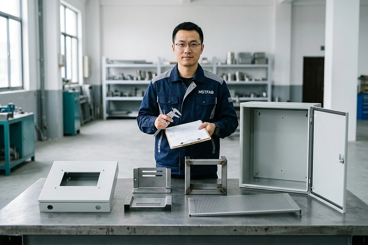
For OEM procurement teams, the key question is whether the supplier can deliver the approved metal components with the right geometry, hardware, finish and inspection requirements.
What Automation Sheet Metal Parts Can MSTFAB Manufacture?
| OEM component | What buyers should check |
|---|---|
| HMI and control panels | Display cutouts, mounting holes and visible finish |
| Sensor mounting brackets | Functional datums, slots and installation alignment |
| Welded equipment frames | Squareness, mounting interfaces and post-weld dimensions |
| Machine guards and covers | Approved openings, edge conditions and service access |
| Empty equipment enclosures | Door fit, mounting plates, cable-entry interfaces |
| Conveyor support parts | Bracket positions, fastening details and assembly fit |
These parts support automation machinery but do not include the finished operating systems.
Why Mechanical Interfaces Matter
Automation equipment combines many individual components. A sensor bracket may need precise alignment with its target. An HMI panel must fit the approved display. A welded frame must support the required mounting locations.
The supplier should review critical interfaces before cutting, bending or welding. Functional dimensions should be identified in the drawing, and any proposed manufacturing change requires OEM approval. A small bracket should not be the reason an expensive automation line cannot be assembled.
What Should OEM Buyers Include in the RFQ?
A useful quotation package includes the approved STEP/STP model, controlled PDF drawings, material specifications, quantities and functional requirements. For assemblies, also provide the BOM, mating-part information, critical mounting dimensions, hardware specifications, finish and inspection requirements.
Clarify whether you need individual components, loose kits or mechanically assembled parts, because a part quotation and an assembly quotation are not the same scope. For a fuller list of what to put in the package, see the automation equipment drawing package checklist.
Manufacturing and Quality Scope
Depending on the approved drawings, MSTFAB can provide laser cutting, CNC bending, welding, mechanical hardware installation, dimensional inspection and export packaging. Project-specific surface finishing may be coordinated through established external finishing partners.
First-article inspection and repeat-order quality requirements should be agreed before production.
Clear Responsibility for OEM Integration
MSTFAB supplies
Drawing-approved sheet metal panels, brackets, frames, guards, covers, empty enclosure shells and agreed mechanical subassemblies, manufactured according to the approved fabrication scope.
The OEM or system integrator supplies and validates
Sensors, motors, PLCs, electronics, wiring, software, functional machine performance and final equipment safety.
Request an Automation Sheet Metal Fabrication Quote
Looking for a custom sheet metal parts supplier for automation equipment? Send MSTFAB your STEP and PDF drawings, material, quantities, mounting interfaces and finish requirements. Explore our custom sheet metal fabrication services.
Email: [email protected] · Website: https://mstfab.com/ · WhatsApp: +86 173 2831 6456
You design the automation equipment. We fabricate the approved metal parts.
Drawing Detail: Sensor Brackets and Mounting Panels
The sections below explain how to define sensor brackets and mounting panels so the approved drawing controls function, not only the outline.
AUTOMATION DRAWING CHECKLIST
An automation sensor bracket or mounting panel succeeds when the drawing controls the sensing datum, adjustment direction, cable clearance, stiffness, fasteners, finish masks and inspection method. A precise laser-cut outline cannot rescue an undefined mounting interface.
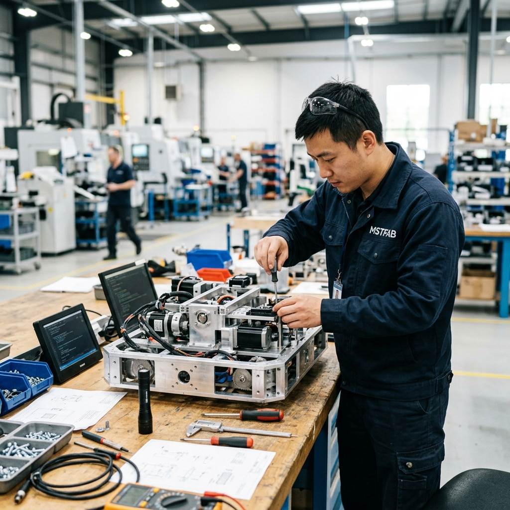
Start With the Sensor-to-Target Relationship
| Drawing input | What to define | Why it matters |
|---|---|---|
| Functional datum | Machine surface or feature that controls sensing position | Avoids tolerance chains from convenient edges |
| Sensing axis | Nominal direction, target and allowed position range | Connects bracket geometry to function |
| Adjustment | Slot direction, travel, locking method and witness marks | Allows setup without uncontrolled movement |
| Cable route | Connector envelope, bend radius, clip points and keep-out zone | Prevents interference and service damage |
| Load case | Mass, acceleration, vibration and accidental contact assumptions | Gives stiffness review an approved basis |
| Inspection | Critical dimensions, gauge, fixture or component-fit method | Makes first-article acceptance repeatable |
Control Bend-to-Hole Geometry
Sensor and fastener holes near a bend can move with material, tooling, bend radius and springback. Dimension functional features from the correct formed datum and identify which relationships are critical after bending. Avoid tightening every dimension when only two or three interfaces decide fit.
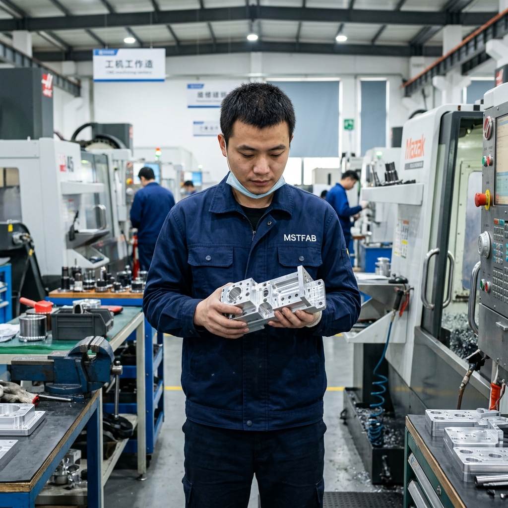
Provide Adjustment Without Creating Flex
Slots can simplify commissioning, but long slots, narrow webs and unsupported offsets can reduce stiffness. Define adjustment travel, clamp area, washer or fastener geometry and the load basis. The responsible machine designer should approve vibration and safety assumptions.
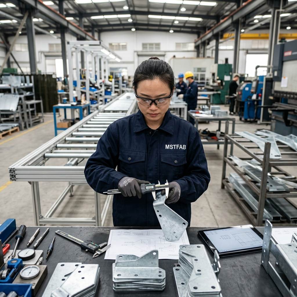
Plan Cable, Connector and Service Clearance
Show the sensor body, connector, cable exit and required bend space in the assembly model. Include access for tightening, replacement and cleaning. A bracket can be dimensionally correct and still be impossible to service when a connector points into a guard.
Mask Functional Contact Areas
Powder coating changes hole size, grounding contact and stack-up. Identify masked faces, threads, studs, locating surfaces and conductive contact zones. Cosmetic finish, corrosion protection and electrical bonding are different requirements and should not be hidden in one paint note.
Buyer Trust Table
| Supplier statement | Evidence to request | Buyer value |
|---|---|---|
| “Precision bracket” | Functional datums and critical formed dimensions | Defines precision for the machine interface |
| “Adjustable” | Travel, clamp area, tool access and lock method | Prevents weak or unusable slots |
| “Cable clearance checked” | Component envelope and service keep-out model | Protects installation and maintenance |
| “FAI passed” | Report tied to revision and representative fit check | Connects approval to the intended function |
Sensor Bracket and Panel Drawing Checklist
- Sensor and target shown in the assembly model
- Functional machine datums identified
- Sensing axis and allowed range defined
- Adjustment travel and lock direction shown
- Cable, connector and tool access reserved
- Load and vibration assumptions supplied
- Bend-to-hole CTQs marked
- Hardware part numbers and access checked
- Finish masks and grounding zones defined
- FAI method and representative gauge agreed

Frequently Asked Questions
Should sensor holes be dimensioned from the nearest edge?
Only when that edge is the functional datum. Otherwise dimension from the machine interface that controls sensor position.
Are slots always better than fixed holes?
No. Slots add adjustment but can reduce stiffness or allow movement. Use them when the adjustment range and locking method are defined.
Does MSTFAB select or calibrate sensors?
No. Standard scope is drawing-defined sheet metal fabrication. Sensor selection, wiring, calibration and system validation remain with the buyer.
Does MSTFAB build complete automation machines or program PLCs?
No. MSTFAB fabricates drawing-defined sheet metal parts such as panels, brackets, frames, guards and empty enclosure shells. Machine assembly, electrical integration, PLC programming and robotics software remain with the OEM or system integrator.
Can parts be supplied as loose components, kits or mechanically assembled parts?
This depends on the approved drawings and the RFQ scope. State whether you need individual components, loose kits or mechanically assembled parts, because each scope is quoted and inspected differently.
Who validates machine function and safety?
The OEM or system integrator. MSTFAB manufactures the mechanical components according to the approved fabrication scope; functional machine performance and final equipment safety are validated by the buyer.
Send the Assembly Context With the Part Drawing
Share the bracket or panel drawing, mating geometry, sensor envelope, load assumptions, finish, quantity and FAI requirements for a fabrication review.
 WeChat Contact
 WhatsApp Me Directly