
We have all been there: it is 11:30 PM in Chicago or Munich, and 1:30 PM here in our Guangzhou plant. Your project manager is breathing down your neck asking why the prototype chassis hasn’t shipped yet. Meanwhile, our tooling programmer is squinting at page 4 of your 2D PDF drawing, trying to figure out whether an internal return flange folds toward heaven or toward earth.
⚡ Direct Plain-English Answer: Why STEP Files Cut Sheet Metal Lead Times in Half
Sending only a 2D PDF drawing for a custom multi-bend sheet metal enclosure is like ordering custom furniture from IKEA using only a hand-drawn postcard. A 3D STEP (.stp / .step) file gives the factory an unambiguous mathematical solid model that feeds directly into automated laser nesting, press brake bend simulations, and tooling clash detection within minutes. However, a STEP file cannot stand alone: 3D models define nominal geometry, while 2D PDFs legally dictate critical tolerances, tapped threads, PEM clinch hardware, surface finish, and quality inspection criteria. Pair them together, and you turn a 5-day email interrogation into a 24-hour quotation and instant machine scheduling.

1. The Real Shop-Floor Drama: When 2D Drawings Stalled an OEM for 6 Days
After years of manufacturing custom sheet metal enclosures, brackets, and structural frames for overseas OEMs, we can state a plain truth: the biggest delay in custom fabrication is almost never raw material availability or laser cutting speed. It is the friction of deciphering drawings.
Recently, an overseas hardware buyer sent an urgent RFQ for a multi-bend 5052 aluminum power supply housing. The submission arrived with five beautifully detailed 2D PDF drawings. On paper, it looked like an open-and-shut case. But when our tooling team zoomed in, the ambiguities piled up:
- First-Angle vs. Third-Angle Projection Confusion: The drawing mix-and-matched projection styles, making it 50/50 whether a bracket ear was folded inward or outward.
- Floating Mounting Holes: Critical standoff holes were dimensioned from an outside formed edge without defining the inner bend radius ($R$) or material stretch allowance.
- Mystery Fasteners: Notes stated “Install standard clinch studs”, but omitted thread pitch, standoff barrel height, and whether the head should flush on the inside or outside face.
- The Bending Punch Trap: A deep return channel had only 12 mm of throat clearance—virtually guaranteeing that our standard press brake punch would smash into the opposite wall on the final hit.
We exchanged ten emails across six days. The buyer was stressed about their assembly line date; our engineers refused to cut expensive metal on a gamble. Finally, the customer exported and emailed their native STEP AP214 file.
What happened next? Within exactly 15 minutes in our CAD software, our DFM team rotated the solid body, detected the punch collision, added a 1.5 mm relief notch to clear our standard punch holder, verified the flat blank, and released the quote. Six days of anxiety solved in a quarter of an hour.
2. Behind the Fiber Laser: Why Automated 3D Unfolding Beats Manual Redrawing
When you only send a 2D PDF, what do you think happens on the factory floor? A programmer has to manually redraw your part’s perimeter line-by-line into CAM software. Every manual click is a human error waiting to happen—a missed notch, an inverted offset, or a misplaced slot.
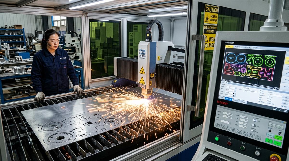
With a 3D STEP model, our sheet metal CAM system extracts the exact 3D solid geometry automatically:
- Automated Feature Extraction: Laser cut perimeters, internal holes, countersinks, and corner radii are extracted in seconds without redrafting.
- Pierce Clearance Verification: The software automatically checks if hole-to-edge distances violate minimum laser piercing thresholds ($> 1.5 imes ext{sheet thickness}$) to prevent heat warping.
- High-Yield Nesting Optimization: Parts from multiple orders sharing the same alloy and thickness are nested together dynamically, minimizing scrap metal and driving down your unit cost.
Buyers often think: “I’ll help the factory by sending an unfolded DXF flat pattern!” Please don’t! Your CAD software calculated that flat blank using a default textbook K-factor (e.g., 0.33). Our shop uses calibrated press brakes with specific V-die widths (e.g., $V=6T$) and empirical bend deduction tables (e.g., K=0.42 for 5052-H32). If we cut your pre-unfolded DXF, the final folded enclosure will be off by 1 to 2 mm. Always provide the folded 3D STEP model and let our tooling engineers unfold it to match our physical dies.
3. Press Brake Bending: Virtual 3D Simulation vs. Crushed Metal
Sheet metal bending is an art governed by hard physics. When a press brake punch drives sheet metal into a V-die with 80 tons of hydraulic pressure, there is zero room for guesswork.

When our engineers open your STEP model, offline bending software runs a complete virtual crash test:
- Bend Sequence Planning: Determining which flange bends first, second, and last to avoid trapping the workpiece inside the machine bed.
- Backgauge Positioning: Ensuring the machine fingers have a solid flat resting surface to index each bend accurately within ±0.2 mm.
- Collision Detection: Flagging whether a deep side-wall will hit the punch holder before reaching 90 degrees. Catching this in CAD saves tooling, raw materials, and weeks of prototype delays.
4. The Golden Rule: Why a 3D STEP File Cannot Replace Your 2D PDF Print
Here is the flip side that many younger hardware designers overlook: a STEP file is not a magic wand. It tells us what the nominal geometry looks like, but it cannot tell us how to build or inspect it legally.
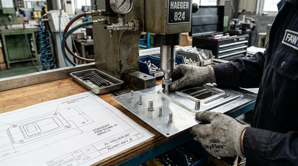
Unless you are using advanced Model-Based Definition (MBD) with embedded 3D PMI (which fewer than 5% of OEMs actually configure), standard STEP files leave out critical manufacturing DNA:
- Tapped Threads: A STEP file shows a simple cylindrical hole. It does not tell us whether that hole is an M4x0.7, an M5x0.8, or a 10-32 UNF thread. (Pro tip: never model physical helical threads in CAD—it crashes CAM unfolding software! Model the tap drill size and specify the thread callout on the 2D PDF.)
- PEM Fastener Specs: A cylinder in CAD could be a through-hole, a blind rivet, or a self-clinching standoff. Your 2D drawing gives the exact manufacturer part number (e.g., PEM SO-M3-8ZI).
- Tolerances & GD&T: A 3D model only knows nominal numbers. It does not know if that center distance is a loose ±0.5 mm or a precision ±0.05 mm dowel pin fit.
- Coating & Masking: Powder coating adds 60 to 100 microns of thickness. Your 2D PDF specifies which grounding studs or internal faces must be masked with high-temp tape.
5. OEM Buyer Trust Matrix: Assumptions vs. Shop-Floor Reality
To build genuine trust between procurement teams and our shop floor, here is our transparent breakdown of what commonly goes wrong and how the STEP + PDF combination protects your budget:
| Buyer RFQ Assumption | Factory Floor Reality (PDF Only) | The STEP + PDF Resolution | Direct Benefit |
|---|---|---|---|
| “2D orthographic views are crystal clear.” | Overlapping bend lines cause inverted flanges or mirror-part scrap. | 3D solid model rotated in CAD confirms 100% flange orientation. | Zero scrap parts due to projection errors. |
| “Factory can guess the bend deduction.” | Generic calculations cause out-of-tolerance final outer dimensions. | Tooling engineers apply empirical K-factors to native 3D solid model. | First-time assembly fit without manual grinding. |
| “Quote should arrive in 4 hours.” | Engineers spend 2 days manually calculating blank sizes and weld times. | Automated nesting software extracts sheet utilization and cut time instantly. | Binding quotation delivered within 24 hours. |
| “Assembly parts will mate smoothly.” | Screw heads or rivet tails collide with internal brackets during integration. | Assembly STEP file run through virtual clash detection before cutting. | Pre-production DFM clearance fixes. |

6. From CAD to Ocean Freight: Quality Inspection & Safe Export Crating
A perfectly manufactured sheet metal enclosure is useless if it arrives at your warehouse with scratched powder coating or bent corners. At MSTFAB, quality verification begins in metrology and ends at the container seal.
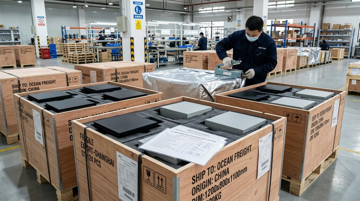
Before export dispatch, every production batch passes:
- First Article Inspection (FAI): Optical CMM or digital calipers verify critical hole pitches against the approved 2D drawing title block.
- Coating Adhesion & Thickness: Cross-hatch adhesion testing (ASTM D3359) and digital film thickness checks (60–90 μm target).
- Export Packaging Standards: Parts are wrapped in low-tack protective PE film, cradled in high-density EVA foam inserts, sealed with desiccants in VCI moisture-barrier foil, and banded inside heavy-duty ISPM-15 heat-treated plywood crates.
7. The 8-Item RFQ Checklist for 24-Hour Turnaround
Want the fastest quotation and most competitive volume pricing? Drop these eight technical items into your RFQ package:
- 3D STEP File: AP214 format (or AP242 with PMI). Single part or exploded assembly.
- 2D PDF Drawing: Vector drawing with title block, revision level, and critical tolerances.
- Material Grade: Exact alloy (e.g., Al 5052-H32 vs. 6061-T6; Stainless 304 vs. 316L; Galvanized SECC).
- Sheet Thickness: Specified in metric millimeters with allowable tolerance.
- Surface Treatment: Powder coat RAL color and gloss level, clear anodize, zinc plating, or brushed finish.
- Fastener Part Numbers: Specific manufacturer hardware codes (PEM, Southco).
- Batch Quantities: Quantities for prototype validation (e.g., 5 pcs) and production runs (e.g., 500 pcs).
- Shipping Destination: Incoterms (FOB, CIF, DDP) and postal code for accurate freight estimation.
Verified Manufacturing Standards & Quality Norms:
- ISO 10303 (AP214 / AP242): Industrial product data exchange standard for 3D neutral CAD files.
- ISO 2768-mK: General tolerances for linear dimensions and geometrical tolerances without individual callouts.
- DIN 6935: Cold bending of flat steel products — flat blank length calculation and bend allowance.
- AWS D1.1 / ISO 5817: Weld joint quality levels and inspection criteria for sheet metal assemblies.
8. Frequently Asked Questions (FAQ)
Q1: Which STEP format should I export from SolidWorks or Inventor: AP203, AP214, or AP242?
Always export in AP214 for standard custom sheet metal fabrication. AP214 preserves surface color tags, layer grouping, and assembly parent-child structures. If your team embeds 3D GD&T dimensions directly on the model (Model-Based Definition), export in AP242. Avoid AP203—it is an obsolete 1990s protocol that strips surface colors and assembly layers.
Q2: What happens if my CAD model has sharp, zero-radius bends?
In real metal bending, zero-radius bends do not exist; steel will crack if forced around a razor edge. When automated CAM software encounters a model with sharp zero-radius bends, it cannot calculate K-factors and will fail to unfold. Always model your inside bend radius ($R$) close to material thickness ($R \approx T$). If you submit a sharp-bend model, our DFM engineers will adjust the radius to standard punch tooling and verify it with your team.
Q3: How do you handle thickness variations between CAD nominal and physical stock?
Commercial sheet metal coils have rolling tolerances (e.g., nominal 2.0 mm aluminum often measures 1.93–2.04 mm). During First Article Inspection, our press brake operators measure actual incoming coil gauge with micrometers and adjust backgauges and V-die depths to ensure external mating dimensions match your drawing.
Get a 24-Hour DFM Review & Sheet Metal Quotation
Ready to eliminate quotation delays and manufacturing misunderstandings? Send your 3D STEP files and 2D PDF engineering drawings to MSTFAB’s technical team for instant CAM unfolding, tooling feasibility verification, and competitive volume pricing.
 WeChat Contact
 WhatsApp Me Directly