
A vehicle-mounted medical equipment enclosure has to remain mechanically stable through road vibration, braking, cornering, shock events, repeated door use and maintenance inside a restricted installation envelope. These conditions place very different demands on brackets, welds, hinges, latches, mounting plates and installed hardware than a stationary cabinet.
Quick answer: Vehicle-mounted medical enclosure DFM is the review of dynamic load paths, reinforced mounting interfaces, weld distortion, fastener retention, door security, internal stiffness, cable movement and service access before sheet metal production. OEM buyers should define the complete equipment mass, center of gravity, vehicle interface, mounting orientation, approved load cases, bracket geometry, environmental exposure and first-article acceptance plan. The goal is an enclosure shell that can be manufactured consistently, installed with the intended tools and validated by the OEM in the configured vehicle system.
Scope note: MSTFAB provides drawing-based custom sheet metal enclosure fabrication for enclosure bodies, welded frames, brackets, mounting plates, doors, installed hardware interfaces, grounding features and finishes. We do not design the finished medical device, determine vehicle shock or vibration profiles, certify the installed system or approve its regulatory strategy. The OEM owns the equipment loads, structural calculations, vehicle integration, electronics, applicable standards and final system validation.
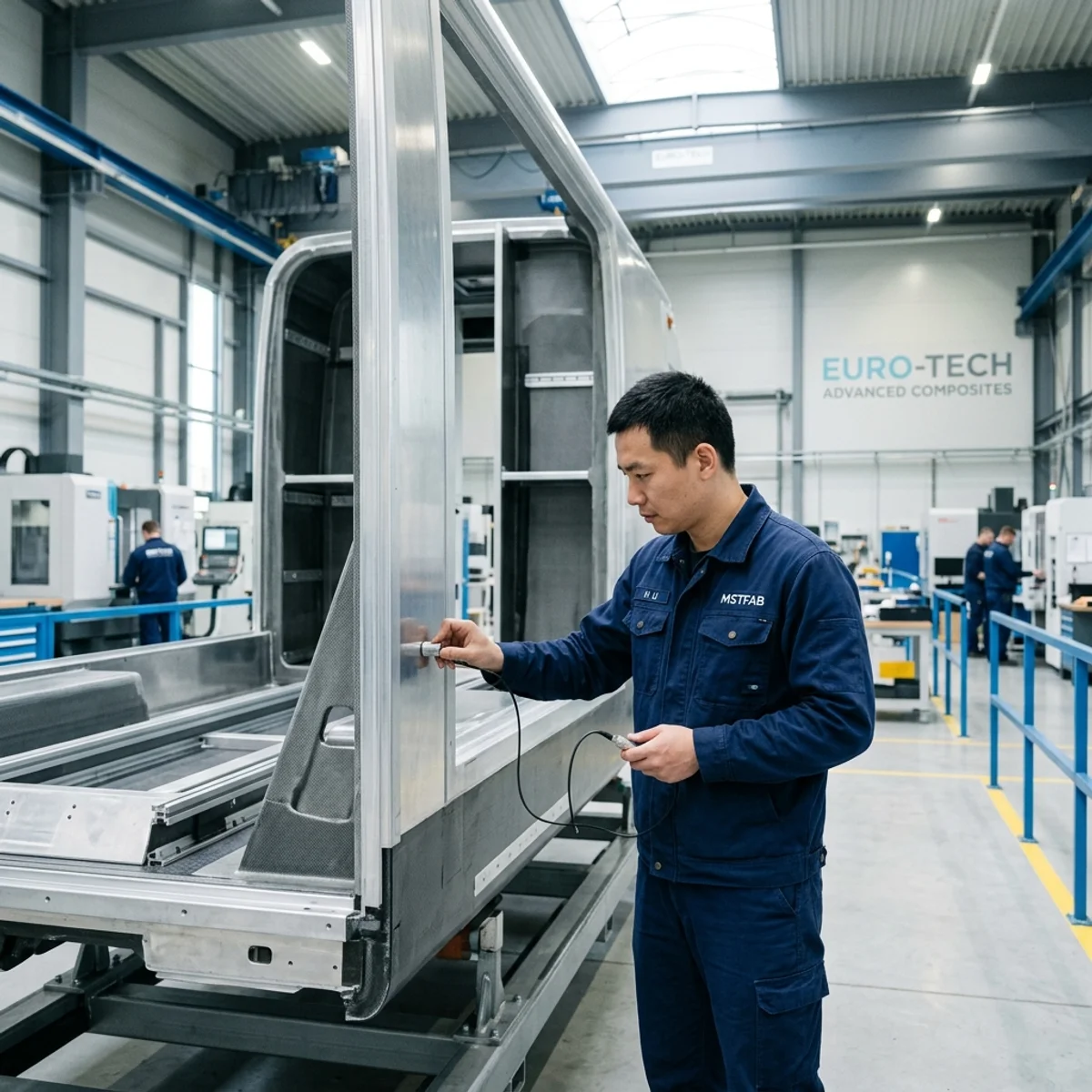
Why Mobile Enclosures Need a Different DFM Review
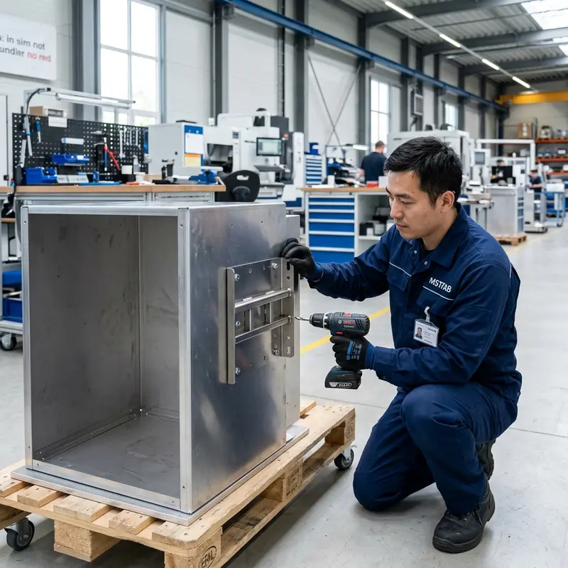
A stationary cabinet is commonly loaded by its own weight, installed components, door operation, and occasional handling. A vehicle-mounted enclosure experiences those loads plus continuous input from the road and vehicle. The direction and magnitude change over time, and repeated cycles can expose weak interfaces that look acceptable during a static shop-floor inspection.
The vehicle installation also constrains access. Walls, seats, stretchers, trim panels, floor structures, and adjacent equipment may prevent a technician from reaching fasteners or removing a door. The correct enclosure is therefore not only strong enough; it can be installed, inspected, serviced, and replaced within the real vehicle envelope.
- Shock events: potholes, curb impacts, emergency maneuvers, and transport handling.
- Repeated vibration: cyclic loading at brackets, holes, weld ends, and hardware.
- Dynamic door loads: added display mass, latch movement, and open-door motion.
- Restricted maintenance: access from one side and limited tool approach.
Define the Load Cases Before Selecting Sheet Thickness
DFM cannot replace structural engineering inputs. The OEM or qualified engineering team should define the loads and acceptance criteria. The fabricator can then identify whether the proposed geometry is practical to cut, bend, weld, assemble, inspect, and reproduce.
| Design input | Why it matters to sheet metal | Typical drawing output |
|---|---|---|
| Complete mass and center of gravity | Determines moment loads at brackets, hinges, and mounting points | Approved equipment envelope and load reference |
| Acceleration or shock cases | Defines force direction and peak demand at interfaces | Bracket and fastener requirements from OEM analysis |
| Vibration profile and duration | Highlights fatigue-sensitive holes, welds, and cantilevers | Test plan and critical feature controls |
| Vehicle mounting surface | Controls bracket position, tolerance stack, and installation access | Datum scheme and interface dimensions |
| Service and crash-related requirements | Affects retention, access, and project validation scope | OEM-controlled specification and acceptance evidence |
Design principle: adding thickness everywhere is not a substitute for understanding the load path. Local reinforcement, folded sections, shorter spans, and improved bracket geometry may deliver stiffness with less mass.
Build a Continuous Load Path
Loads should travel from the installed equipment through mounting plates and enclosure structure into the vehicle attachment points without relying on a broad, unsupported sheet to distribute everything.
Use Bends as Structure
Returns, hems, channels, and hat sections increase section stiffness and can reduce reliance on welded additions. Keep bend radii, flange lengths, tooling access, and nearby holes compatible with the selected material and thickness.
Reinforce Interfaces
Local doublers or formed brackets can spread loads around vehicle bolts, hinges, latches, and heavy internal equipment. Reinforcement should extend far enough to transfer load without ending at another weak section.
Avoid Long Cantilevers
A bracket that projects far from its support amplifies deflection and cyclic stress. Shorten the lever arm, add a return or gusset, change orientation, or connect it to a second structural surface when the assembly allows.
Welded Brackets Need Strength and Dimensional Control
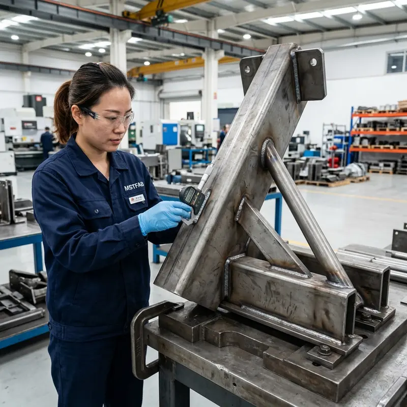
More weld is not automatically a better mobile enclosure. Continuous welds can add heat, distortion, residual stress, weight, finishing work, and inspection complexity. The weld specification should come from the design requirement and joint geometry, while the fabrication plan should control fit-up and protect critical mounting datums.
Bracket holes can move when welding pulls the assembly. Use suitable fixtures, balanced sequencing, accessible joint design, and post-weld inspection. Avoid placing weld ends in highly stressed corners without engineering review, and make sure the welder can reach the specified joint in the real assembly.
- Identify weld type, size, length, location, and any appearance or grinding requirement.
- Dimension vehicle interfaces from functional datums rather than uncontrolled edges.
- Define flatness, squareness, and hole-position checks after welding.
- Review weld distortion control for enclosure frames before freezing cosmetic and mounting tolerances.
Fastener Retention Starts at the Sheet Metal Interface
Threaded inserts, weld nuts, studs, captive nuts, and through-bolts each transfer load differently. Their performance depends on sheet thickness, material strength, hole preparation, edge distance, installation orientation, access, and supplier-approved installation parameters. A fastener callout should identify the exact hardware and the required inspection.
The OEM should define final bolt grade, torque, locking method, joint stack, service replacement, and any retention evidence required for the vehicle. The fabrication drawing should control features that belong to the enclosure: hardware type and location, installation side, flushness where needed, thread protection during coating, and push-out or torque testing if contracted.
Service question: if a captive thread is damaged inside the installed vehicle, can it be repaired or replaced without removing the entire enclosure? The answer may influence the hardware strategy.
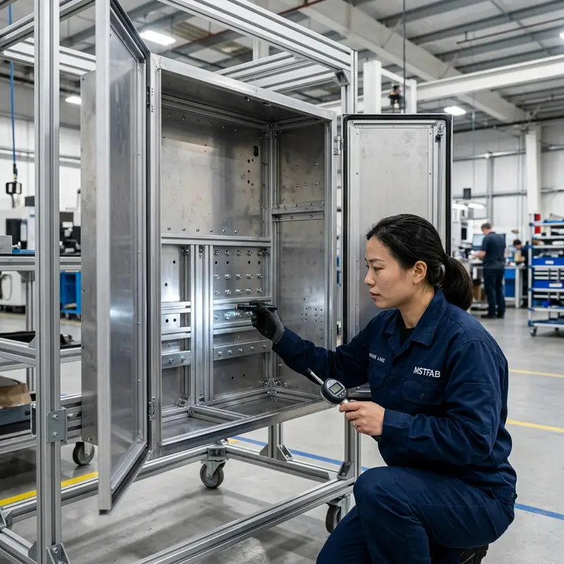
Doors, Hinges and Latches Must Remain Secure in Motion
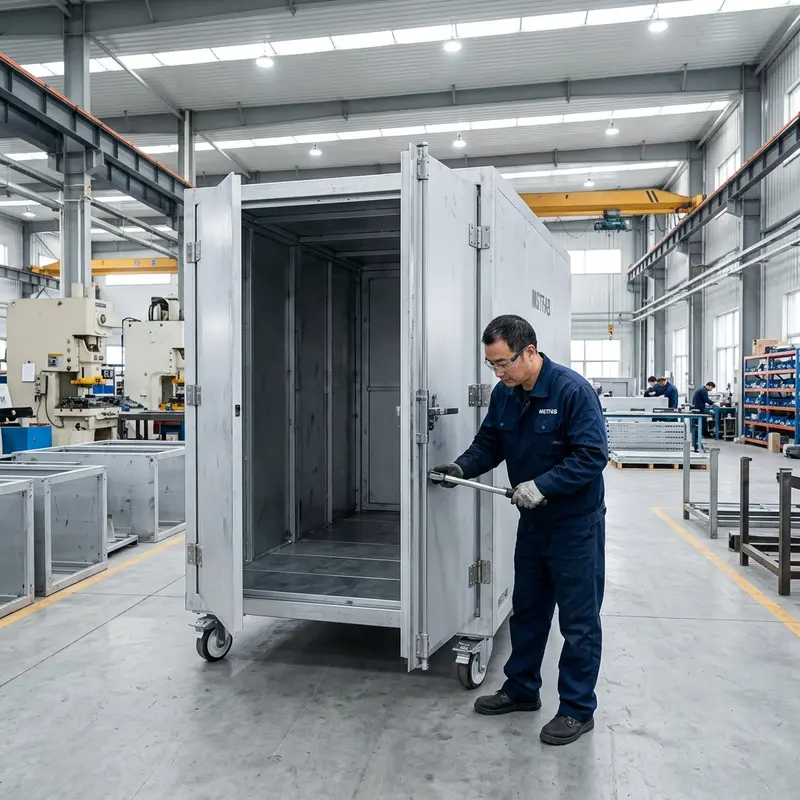
A door may carry an HMI, keyboard, connector panel, controls, or other equipment. Added mass increases hinge moment and can change door sag, latch alignment, and vibration response. Evaluate the configured door, not only the empty sheet metal panel.
The design should prevent unintended opening under defined vehicle conditions and remain operable for routine service. Consider latch engagement, secondary retention if required by the OEM, hinge pin security, door stops, hold-open devices, seal compression, handle clearance, and the effect of cable bundles across the hinge side.
Closed: gap, seal, latch engagement, and retention.
Opening: nearby trim, seats, and equipment clearance.
Open: stay function, cable sweep, and service stability.
Repeated use: hinge wear, alignment, and fastener inspection.
Mounting Plates and Internal Brackets Need Dynamic Stiffness
A large flat mounting plate may satisfy static dimensional checks yet vibrate when populated with power supplies, batteries, pumps, or diagnostic electronics. Identify the mass and location of heavy components. Use formed returns, channels, local supports, or shorter spans to control movement without making every internal panel unnecessarily thick.
Internal brackets should avoid long unsupported projections and provide tool access for assembly and replacement. Their natural response and fatigue life are product-level engineering topics, but manufacturability improves when the drawing clearly defines interfaces, datums, welds, hardware, and critical dimensions.
- Heavy components: place them near supported zones where possible.
- Cable restraint: prevent harness mass from loading connectors during motion.
- Isolation components: define supplier, orientation, preload, and replacement access.
- Clearance: allow movement without impact against the enclosure or door.
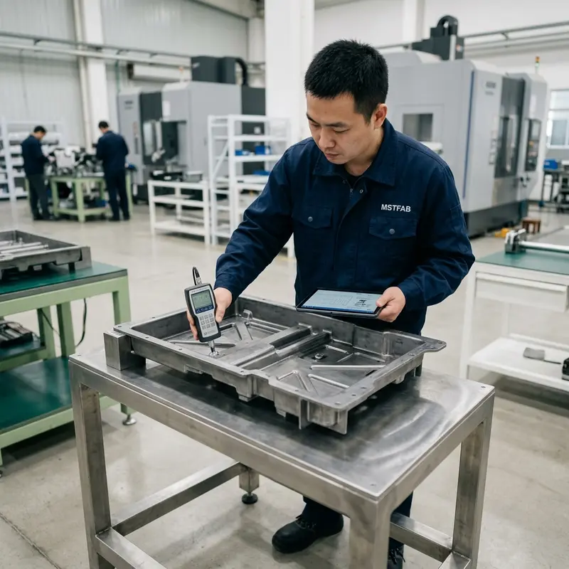
Design Installation and Service Access Into the Vehicle Envelope
Good serviceability reduces downtime and lowers the chance of uncontrolled modification during maintenance. Review access using the complete vehicle installation model and the tools technicians will actually use.
Mounting Access
Confirm bolts can be inserted, held, torqued, marked, inspected, and removed. Avoid hidden nuts that require dismantling vehicle trim unless that sequence is intentional and documented.
Replaceable Modules
Check extraction paths for batteries, power supplies, filters, trays, and mounting plates. The replacement envelope often exceeds the final installed envelope.
Cable and Connector Access
Provide hand and tool clearance, strain relief, bend space, labeling visibility, and a route that does not place service loads on sensitive connectors.
Cleaning and Inspection
Avoid inaccessible debris traps where the application requires regular cleaning. Define removable panels, drainage, edge treatment, and finish requirements from the OEM’s use environment.
Material, Finish and Environmental Inputs
Vehicle interiors can experience temperature variation, humidity, condensation, cleaning chemicals, dust, and contact with dissimilar materials. Material and finish should be selected from the actual use case. Powder-coated steel offers robust, economical construction for many indoor installations; stainless steel can support corrosion and cleaning requirements; aluminum reduces mass but changes forming, joining, thread, and galvanic-interface considerations.
Specify coating system, color, texture, gloss, masking, grounding zones, corrosion preparation, cosmetic surfaces, and acceptable repair criteria. Where condensation or liquid exposure is possible, the OEM should define sealing, drainage, ventilation, and ingress requirements for the complete assembly. The sheet metal supplier can control the contracted physical features but should not imply a finished system rating without the required product-level validation.
Packaging must protect structural datums, coated faces, protruding brackets, and door alignment during international shipment. Heavy doors may need temporary restraints that are removed during installation. Agree on moisture protection, crate orientation, lifting points, labels, and inspection evidence before dispatch.
First-Article Inspection Should Use the Mechanical Assembly
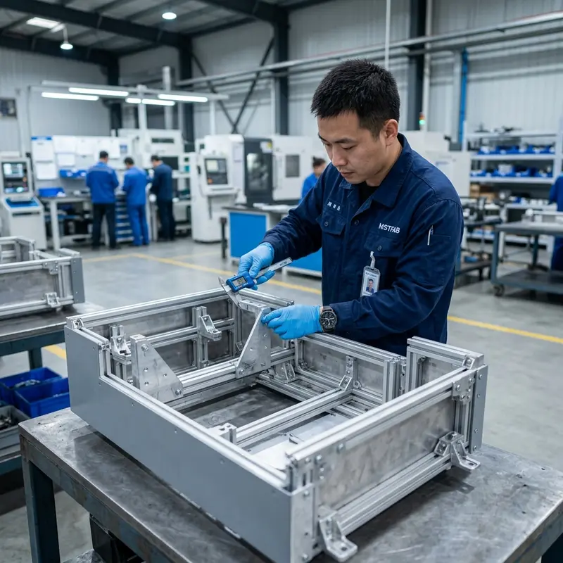
Inspecting individual panels does not prove that the vehicle interface, welded frame, door, mounting plate, and brackets work together. Build the relevant assembly and check it in the condition defined by the OEM. A vehicle-interface checking fixture can reproduce mounting datums when the actual vehicle is unavailable.
- Verify mounting-hole position, bracket geometry, flatness, and enclosure squareness.
- Install representative mass or approved dummies at critical equipment locations.
- Check door gap, hinge movement, latch retention, stays, and cable sweep.
- Confirm tool access to vehicle bolts, internal hardware, and service components.
- Inspect welds, installed fasteners, coating, masked grounds, labels, and packaging.
- Record deviations and obtain buyer approval before repeat production.
This inspection demonstrates mechanical fit and workmanship. It does not replace the OEM’s shock, vibration, vehicle, medical-device, electrical, or regulatory validation.
Vehicle-Mounted Enclosure RFQ Checklist
A complete sourcing package allows a meaningful DFM review and separates fabrication requirements from product-level engineering assumptions.
Controlled design: STEP assembly, dimensioned PDF, revision, units, tolerances, materials, finish, and BOM.
Load inputs: equipment mass, center of gravity, mounting orientation, load cases, and OEM-approved bracket design.
Vehicle interface: datum scheme, mounting surface, tolerance stack, access envelope, neighboring equipment, and lifting method.
Quality plan: critical dimensions, weld criteria, hardware tests, fixtures, reports, appearance, and first-article quantity.
Compliance flow-down: applicable supplier documents, traceability, change notification, cleanliness, and record retention.
Commercial data: prototype and annual volume, schedule, configuration mix, packaging, destination, and spare requirements.
Quality-System and Regulatory Boundaries
Installation in an ambulance or mobile clinic does not automatically mean every enclosure supplier must hold IATF 16949 certification. Likewise, use around medical equipment does not automatically transfer all ISO 13485 or medical-device obligations to the sheet metal factory. The OEM should determine supplier eligibility and flow down the requirements that apply to the specific part, market, and program.
| Project item | MSTFAB fabrication scope | Buyer or OEM scope |
|---|---|---|
| Enclosure body, brackets, and frame | Manufacture to released drawings | Define geometry, load requirements, and interfaces |
| Welds and installed hardware | Control contracted process and inspection characteristics | Approve joint design, fastener system, and acceptance criteria |
| Vehicle shock and vibration | Supply representative samples and agreed records | Define profiles, perform validation, and approve results |
| Medical equipment function | Not supplied as part of an empty shell | Own electronics, clinical function, safety, and regulatory approval |
| Change control and traceability | Follow agreed purchase and quality requirements | Define required notification, records, and supplier controls |
Clear scope builds trust: separate sheet metal manufacturing evidence from finished-device claims. Buyers receive better quotations and more reliable production when every requirement has an owner and an acceptance method.
Frequently Asked Questions
Common questions from engineering and sourcing teams developing mobile medical enclosure programs.
Can the sheet metal supplier determine the vibration load?
The OEM or qualified engineering team should define product and vehicle load cases. The fabricator can review whether the resulting brackets, bends, welds, hardware, and inspection requirements are manufacturable and repeatable.
Is thicker sheet always more vibration resistant?
No. Thickness can help, but load path, unsupported span, formed section geometry, bracket orientation, connection stiffness, equipment mass, and resonance all matter. Local reinforcement may be more efficient than a universal gauge increase.
Should every bracket be continuously welded?
Not automatically. Weld size and length should follow the approved design. Excessive welding can increase distortion and residual stress. Joint accessibility, heat control, fatigue-sensitive details, and post-weld inspection should be reviewed together.
What belongs in the first-article report?
Include critical mounting dimensions, bracket and frame geometry, weld and hardware inspection, door function, representative load or dummy checks, coating, labeling, fixture identification, deviations, and buyer approval status.
Does MSTFAB supply a certified finished medical device?
No. MSTFAB provides drawing-based parts and custom medical equipment enclosure fabrication. The OEM owns vehicle integration, medical function, electrical safety, regulatory approval, and final system validation.
How can buyers reduce sourcing risk?
Freeze the vehicle interface and loads early, provide complete controlled files, identify critical characteristics, agree on first-article evidence, define change notification, and validate the configured assembly before authorizing repeat production.
When to Ask MSTFAB for a Vehicle Enclosure Review
Send your enclosure assembly, vehicle interface, approved bracket design, load inputs, material, finish, quantities, and inspection requirements for a drawing-based manufacturability review. Submit the controlled STEP assembly, dimensioned PDF and sourcing requirements through the MSTFAB contact page.
 WeChat Contact
 WhatsApp Me Directly