
⚡ Direct Answer: How to Prevent Hole Position Drift on Repeat Sheet Metal Orders?
Hole position drift across repeat production batches is caused by 4 mechanical and digital process variables: 1) Progressive Die Punch & Pilot Pin Wear (pilot pins erode by 0.05mm–0.15mm over 50,000 hits, causing progressive strip pitch wander); 2) CAM Nesting Program Desynchronization (uncontrolled CAM programmers re-generating DXF cut files with altered K-factor stretch values); 3) Press Brake Backgauge Inaccuracy (forming parts where bend lines shift relative to punched holes due to operator positioning variation); and 4) Raw Material Coil Thickness Fluctuations. Eliminating hole position drift requires 4 robust engineering controls: 1) Cutting All Critical Hole Arrays Simultaneously on Flat Fiber Lasers Prior to Bending; 2) Deploying Hardened Steel GO/NO-GO Pin Check Fixtures at the brake station; 3) Locking CAM G-Code Programs with Digital Cryptographic Checksums (MD5/SHA-256); and 4) Mandating Tooling Hit-Count Maintenance Logs to re-grind or replace punch pins before wear limits are exceeded.
Few quality defects are more aggravating for an equipment manufacturer than receiving Batch 5 of a custom chassis and discovering that motherboard mounting standoffs are off by 0.8mm, preventing PCB installation. Batch 1 and Batch 2 fit perfectly, but over subsequent months, subtle shop-floor drift accumulated into fatal assembly failure. Establishing strict hole position controls preserves absolute interchangeability across years of repeat builds.
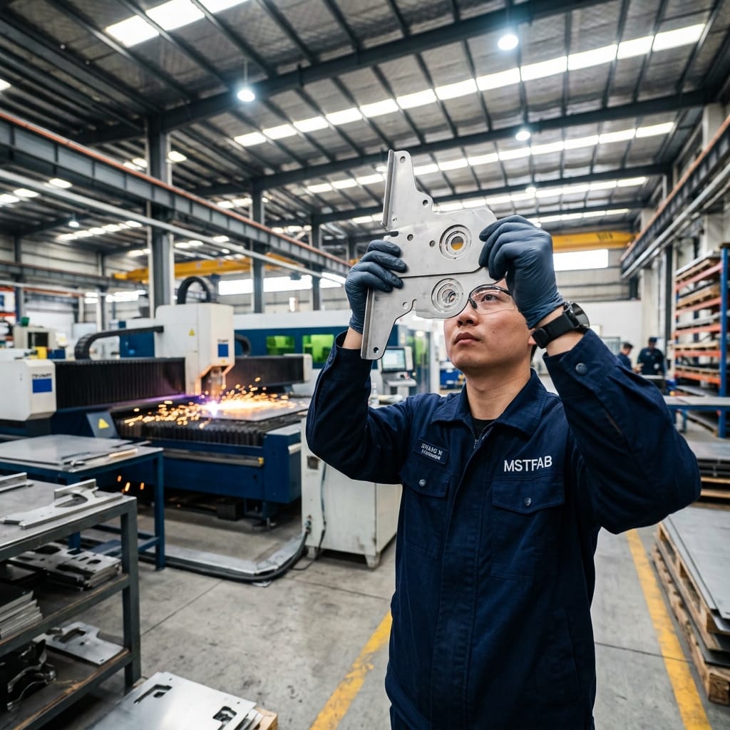
The 4 Root Causes of Hole Position Drift & Engineering Solutions
Diagnose the mechanical root causes of hole drift and implement permanent poka-yoke (error-proofing) countermeasures:
| Drift Vector | Shop-Floor Mechanism | Accumulated Drift | Permanent Engineering Countermeasure (MSTFAB) |
|---|---|---|---|
| 1. Forming After Punching | Holes placed close to bend lines stretch into ovals as metal plastically deforms around the punch radius. | 0.30 – 0.70 mm | Maintain minimum hole edge-to-bend distance of 2.5T + R; or cut laser relief slots along the bend line. |
| 2. Progressive Die Pilot Wear | Hardened steel locating pilot pins wear down from strip friction over 50,000+ strokes, allowing strip pitch wander. | 0.15 – 0.40 mm | Carbide-coated pilot pins + mandatory replacement every 75,000 hits tracked by automated press stroke counters. |
| 3. CAM Program Tampering | CAM programmer re-unfolds the 3D model for Batch 3 using a different K-factor setting (0.33 vs 0.42). | 0.25 – 0.60 mm | Version-lock approved NC cutting programs in centralized ERP with SHA-256 digital checksum verification. |
| 4. Press Brake Backgauge Skew | Operator positions blank against worn backgauge finger stops, introducing angular skew across formed flanges. | 0.20 – 0.50 mm | CNC 6-axis independent backgauges with laser sheet position sensors ensuring automatic zero-clearance squaring. |
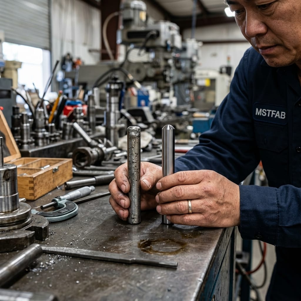
The Hardened Steel Checking Fixture (Poka-Yoke Defense)
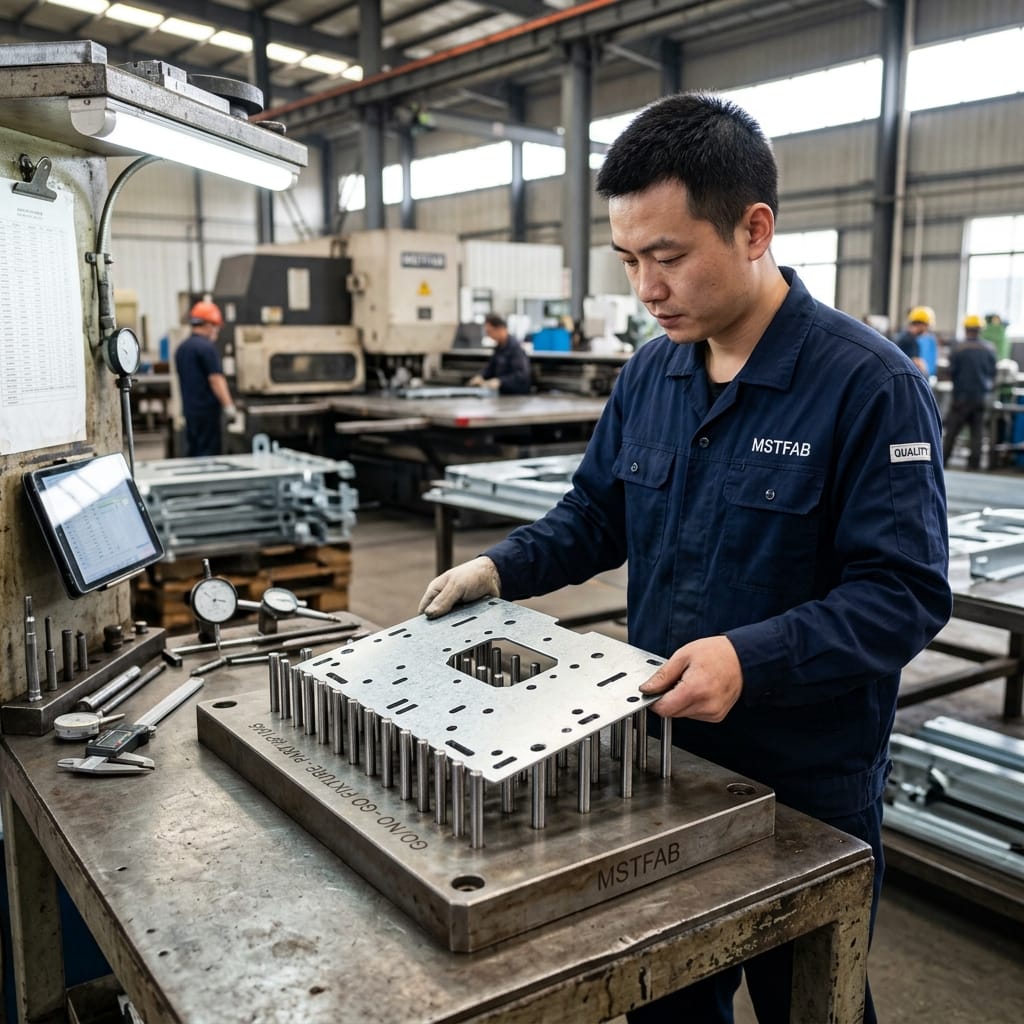
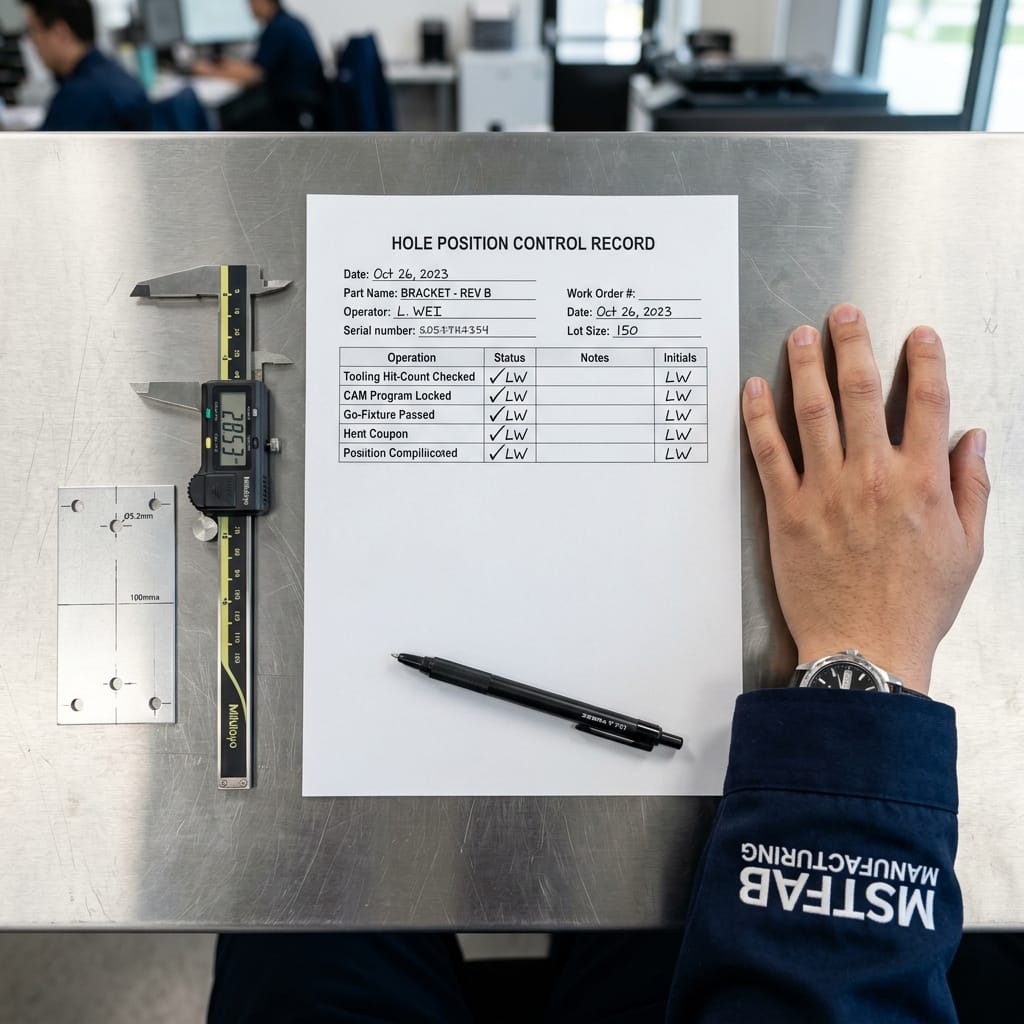
While CMM inspection reports are essential for First Article qualification, they are too slow for high-speed shop-floor batch control. The definitive industrial solution to guarantee zero hole position drift is a dedicated Hardened Steel GO/NO-GO Pin Check Fixture:
- Precision CNC-Machined Baseplate: Built from tool steel (D2 or O1) hardened to 58–62 HRC, mounted on granite reference flats.
- Full-Pin Simultaneous Drop Test: The formed chassis is seated on locating datum pins. Hardened inspection pins representing the mating hardware (e.g. M3 standoffs) must drop smoothly through all holes simultaneously.
- Instant 100% Pass/Fail Verification: If a single hole drifts by more than 0.15mm, the pin binds, alerting the brake operator to recalibrate backgauges instantly before running the next part.
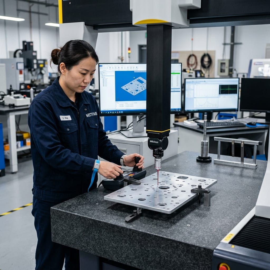

Achieve Flawless Repeatable Sheet Metal Fabrication Consistency With MSTFAB
MSTFAB enforces ISO 9001 certified quality gates, CMM automated metrology, locked CNC bend sequences, and tamper-proof golden sample governance. Guarantee batch-to-batch repeatability from pilot run to mass production.
Frequently Asked Questions (FAQ)
Why does hole position drift more on bent flanges than on flat laser-cut plates?
On a flat laser-cut plate, fiber lasers deliver ±0.05mm positioning repeatability governed purely by linear optical encoders. Once you introduce press brake air-bending, mechanical variables multiply: raw sheet thickness tolerances (±0.08mm), material yield strength variations between coils, and operator backgauge alignment can combine to shift hole centerlines by ±0.30mm to ±0.50mm.
Can a checking fixture be shared between the buyer and the fabricator?
Yes, and this is best practice! Building twin check fixtures from the same master CNC machining program ensures that the fabricator’s final QA gate and the OEM’s receiving dock use 100% identical physical inspection criteria, eliminating disputes over measurement methods.
How does MSTFAB guarantee hole position repeatability across repeat orders?
MSTFAB stores verified CNC laser cutting programs in an immutable ERP archive locked to specific drawing revisions. All press brake setups utilize dynamic laser angle sensors that automatically compensate for coil thickness variations, backed by dedicated check fixtures for all high-volume mating assemblies.
 WeChat Contact
 WhatsApp Me Directly