
DESIGN RELEASE GUIDE FOR OEM TEAMS
A useful sheet metal enclosure drawing does more than describe a box. It connects purchased equipment, doors, thermal interfaces, cable entry, service access, finish and inspection to one buildable revision. This guide shows what buyers and mechanical engineers should freeze before requesting a production quote.
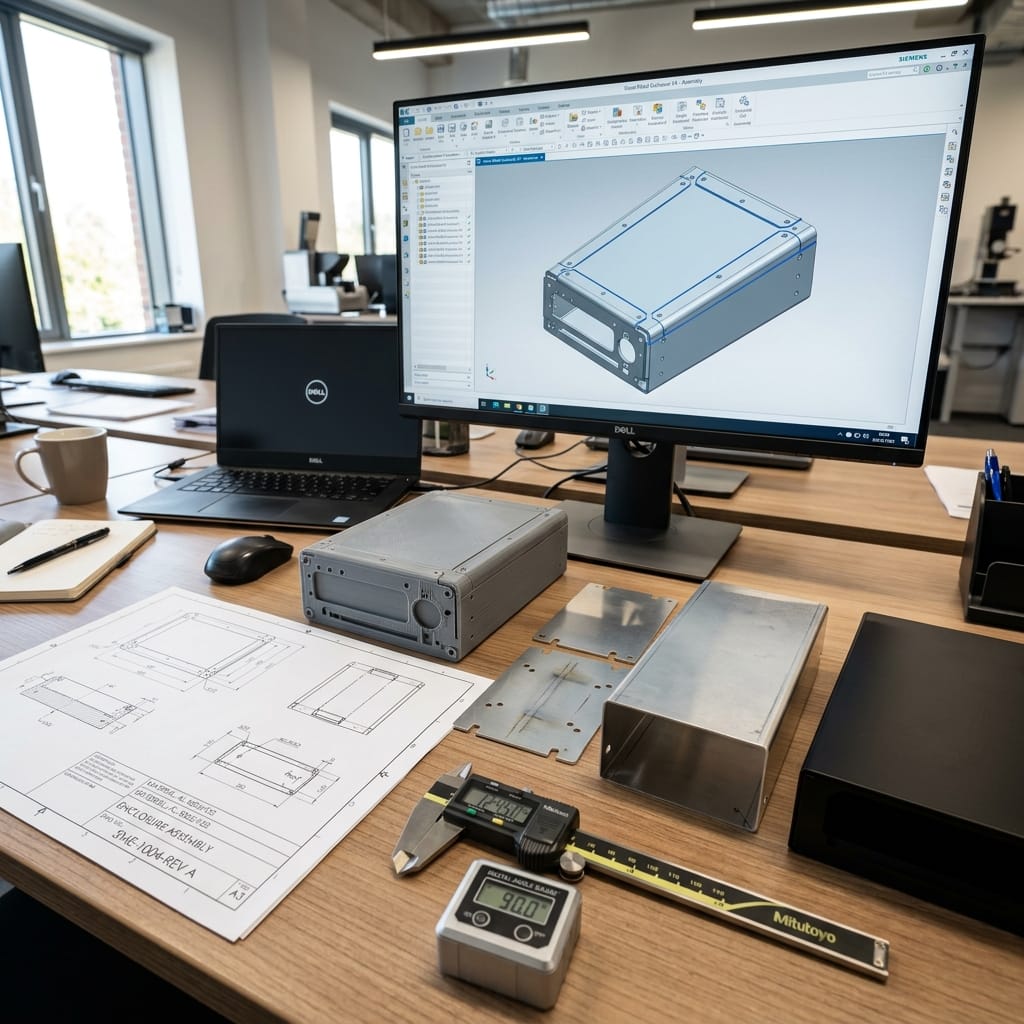
1. Map the Interfaces Before Drawing the Walls
The enclosure should follow the equipment it must hold and the people who must assemble or service it. Mark mounting datums, connector envelopes, screen and button cutouts, cable bend space, removable panels, door swing and tool access. If those inputs arrive after the flat patterns are released, the project has politely scheduled its own rework.
Equipment fit
Provide component models or controlled templates, mounting patterns, keep-out zones and the datum structure used during assembly.
Service access
Define which parts are removed, which tools are used, hinge side, opening angle and clearance around replaceable equipment.
Thermal interfaces
Locate fans, filters, louvers or heat-exchanger cutouts and assign responsibility for the completed thermal design.
Cable and grounding interfaces
Mark gland plates, conductor approach, bend space, studs, masked contact zones and any removable entry panels.
2. Match Bend and Cutout Rules to the Actual Tooling
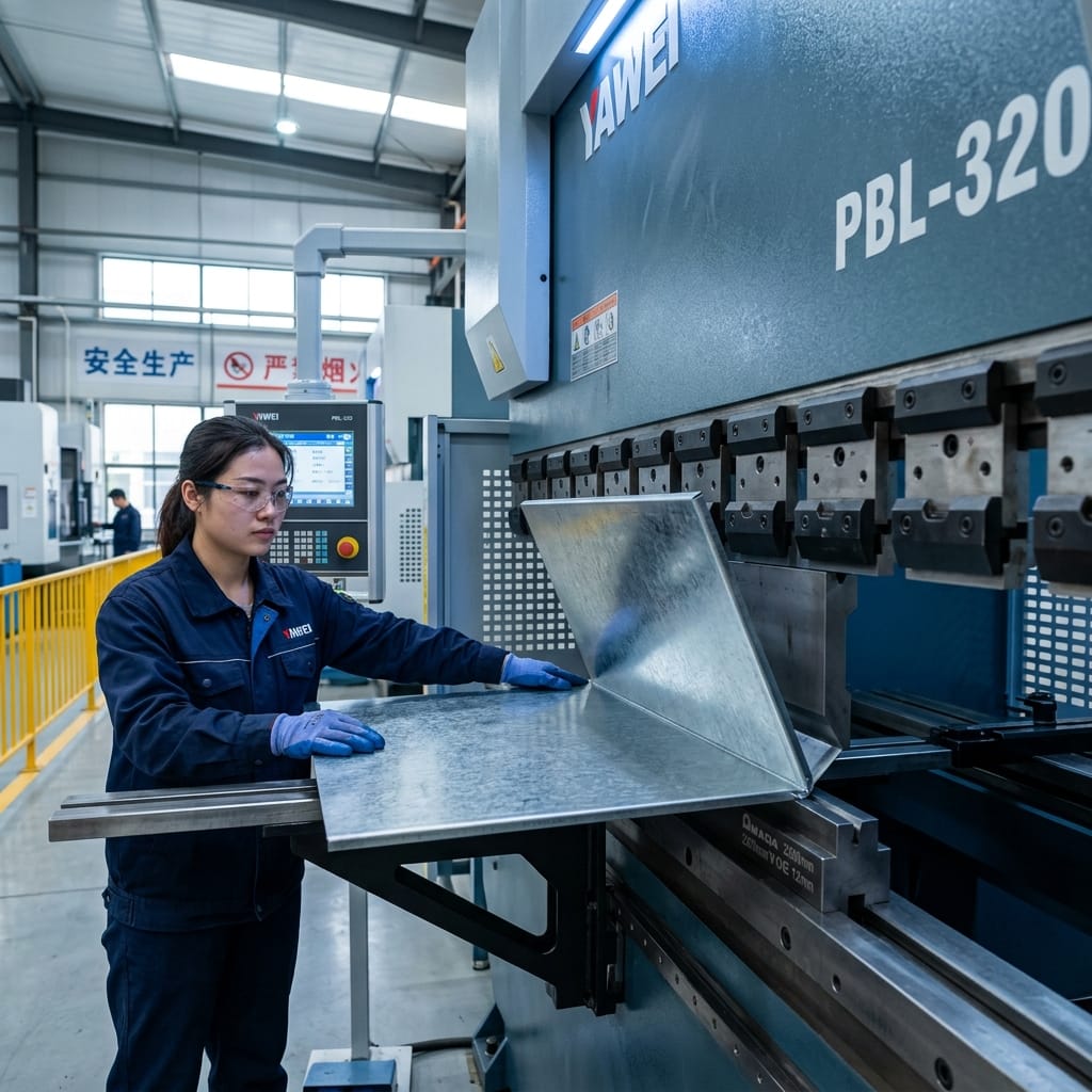
Inside radius, bend relief and hole-to-bend clearance depend on material, thickness, grain direction, punch or laser process and press-brake tooling. Rules such as “always use 1T” or “always keep holes 2T away” can be useful conversation starters, but they are not universal manufacturing laws. Ask the selected fabricator to review the flat pattern before release.

3. Select Material as a System Decision
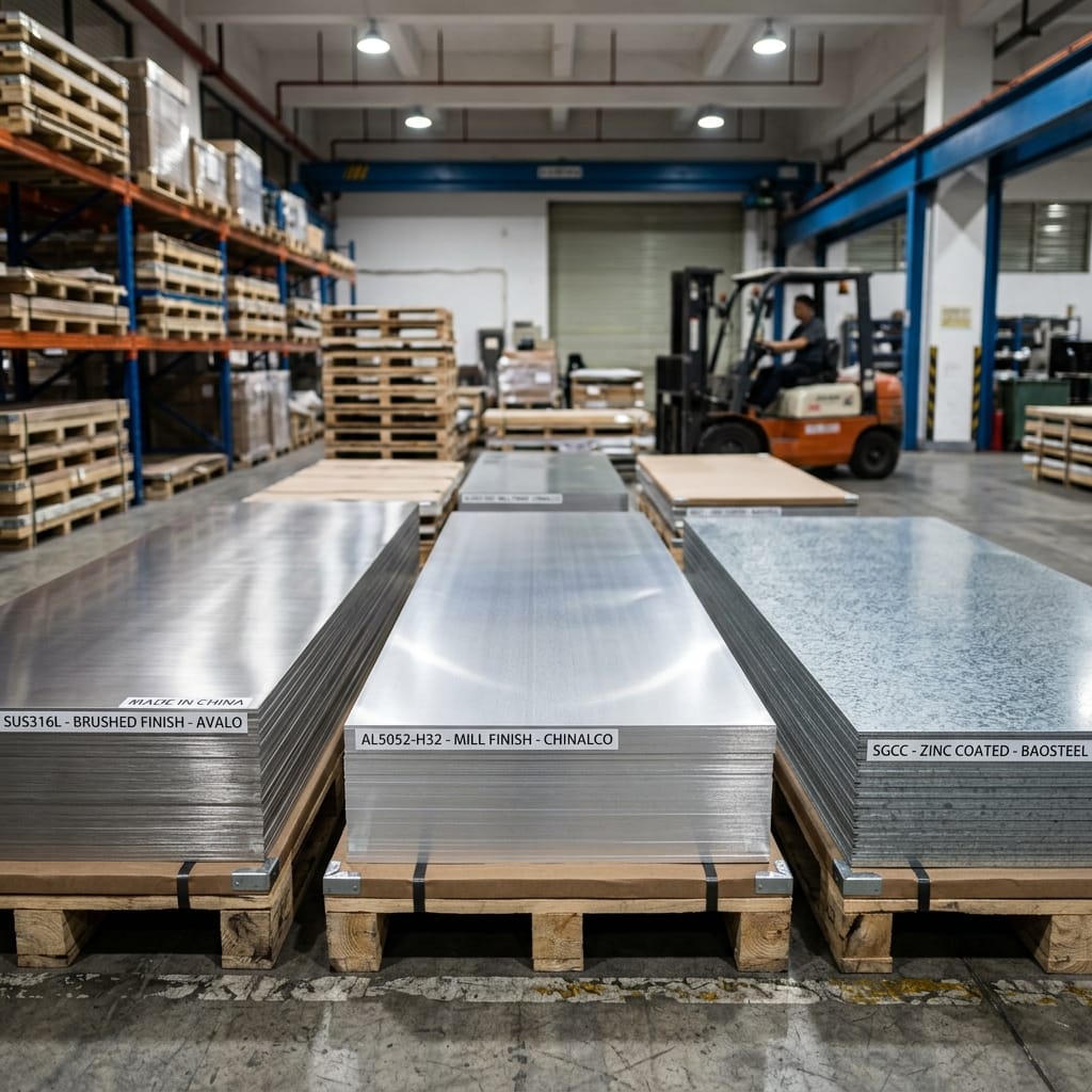
Material choice should reflect structure, corrosion exposure, weight, heat flow, appearance, joining and finish. The drawing should state the grade and any permitted substitution. “Stainless,” “aluminum” or “galvanized” is a material family, not a complete purchase specification.
| Material route | Useful when | Questions to resolve |
|---|---|---|
| Cold-rolled carbon steel | Indoor structures and coated equipment housings | Grade, thickness, corrosion system, welded zones and coating preparation |
| Pre-galvanized steel | Additional corrosion protection is needed at a controlled cost | Coating designation, cut-edge strategy, welding effects and topcoat compatibility |
| Stainless steel | Cleanability or corrosion resistance drives the design | Alloy, finish, weld restoration, contamination control and cosmetic grain direction |
| Aluminum | Weight or thermal behavior matters | Alloy, temper, joining method, distortion risk and anodizing or coating requirements |
4. Design Doors, Seals and Hardware as Relationships
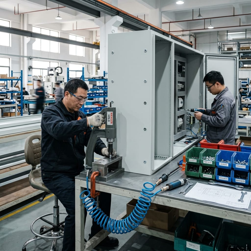
A hinge, latch or gasket cannot be reviewed in isolation. The drawing should define hardware part numbers, mounting method, coating allowance, adjustment, rear clearance and the surfaces that must remain flat or masked. For a sealing target, connect the door return, gasket land, latch compression, corner transitions and every penetration.
Self-clinching hardware can be useful in thin sheet, but the fastener series, material, sheet hardness, edge distance and installation direction must suit the application. Tapped holes, rivet nuts, weld nuts and through-bolts remain valid alternatives when the design calls for them.
5. Use Tolerances Where Function Needs Them
Do not tighten every dimension because one connector must align. Define datums and critical-to-function features, then allow realistic process tolerances elsewhere. Welded assemblies, door openings and large cosmetic panels need different inspection thinking from laser-cut hole patterns.
Agree the measurement method before quotation. Calipers, gauges, fixtures, height measurements or coordinate inspection may each be appropriate. The method should match the risk and be included in the price.
6. Freeze a Production Baseline With the First Article
The first article should confirm more than overall size. Record critical datums, door and panel fit, hardware operation, finish, masked areas and buyer-defined interfaces. Approve the exact drawing and BOM revision used for that sample, then require notification before material, hardware, gasket, coating or manufacturing details change.

Buyer Trust Table
| Buyer question | Evidence to request | Why it matters |
|---|---|---|
| Will purchased equipment fit? | Controlled templates, datum checks and assembly fixture or sample fit | Prevents late drilling, slots and visible gaps |
| Will repeat orders match? | Approved first article, CTQ record and change-notification rule | Protects the released production baseline |
| Is the finish defined? | Color, texture, gloss, coating route, masked zones and approved sample | Separates objective acceptance from opinions under warehouse lighting |
| Who owns final compliance? | Written supply boundary and buyer-owned validation plan | An empty shell quotation is not a completed-equipment certificate |
RFQ Checklist
- Current STEP model and dimensioned drawing
- Part numbers and drawing revision
- Material grade, thickness and substitutions
- Installed equipment and interface templates
- Door, panel and service-access requirements
- Hardware list and installation direction
- Finish, cosmetic zones and masking
- Critical dimensions and inspection method
- Prototype and production quantities
- Packing and delivery requirements
Frequently Asked Questions
What should be reviewed first in an enclosure design?
Start with equipment fit, datums, access, cable routes, thermal interfaces and environmental exposure. These decisions control the enclosure geometry that follows.
Is one bend-radius rule valid for every enclosure?
No. Radius depends on material, thickness, grain direction and available tooling. Keep radii consistent where practical, then confirm them with the selected fabricator.
Does custom fabrication establish an IP or NEMA rating?
No. Metalwork can support a protection target, but the completed configuration, installed components and required verification remain with the responsible OEM or conformity party.
What makes a first article useful?
It links the approved revision to measurable fit, finish and interface evidence, then becomes the baseline for controlled repeat production.
Review the Drawing Before Pricing the Mistake
Send the assembly model, 2D drawings, component templates, material, finish, quantity and critical interfaces. MSTFAB will review the drawing-defined metalwork scope and identify manufacturing questions before quotation.
 WeChat Contact
 WhatsApp Me Directly