
⚡ Direct Answer: How to Define Critical-to-Quality (CTQ) Dimensions in Sheet Metal?
Critical-to-Quality (CTQ) dimensions are the vital 3 to 7 engineering features on a sheet metal drawing that directly govern fit, function, safety, or electromechanical assembly. Attempting to make every dimension on a complex chassis “critical” (the over-tolerancing trap) unnecessarily drives fabrication costs up by 40%–80% and causes endless false inspection rejections. Defining effective CTQs follows a 4-step engineering discipline: 1) Identify Primary Mating Interfaces: Designate mounting hole pitch for PCB motherboards, 19-inch rack slide flange centers, and NEMA gasket compression flanges as CTQs; 2) Mark CTQs with Standardized Symbology: Enclose CTQ dimensions inside oval balloons or diamond markers with explicit datum references; 3) Assign General Tolerance Standards to Non-Critical Features: Rely on ISO 2768-m (Medium) for non-functional cutouts, cosmetic flanges, and clearance louvers; and 4) Mandate In-Process SPC Tracking: Require the fabricator to run control charts exclusively on designated CTQs to guarantee Cpk ≥ 1.33.
A drawing that specifies ±0.05mm tolerances across 80 different dimensions is an engineering disaster. Sheet metal is inherently flexible: bending grain orientation, thermal heat dissipation during welding, and powder coating film accumulation cause natural micro-variances. High-performing engineering teams prioritize what truly matters, ensuring seamless assembly without inflated manufacturing costs.

Over-Tolerancing vs. Prioritized CTQ Architecture
Compare how shifting from indiscriminate over-tolerancing to focused CTQ definitions slashes scrap while improving assembly fit:
| Feature Category | Over-Toleranced Approach (High Cost / Low Value) | Prioritized CTQ Benchmark (MSTFAB Standard) | Shop-Floor Quality Verification |
|---|---|---|---|
| PCB & Drive Mounting Holes | ±0.05 mm on every single hole | <CTQ> True Position ∅0.25mm [MMC] relative to primary Datum A/B | Automated CMM probe inspection; SPC X-bar/R control charts. |
| PEM Clinch Fastener Holes | ±0.02 mm (Requires reaming) | <CTQ> +0.08 / -0.00 mm (Direct fiber laser pierced hole) | Hardened steel GO / NO-GO plug pin gauges at laser shuttle table. |
| Formed Enclosure Overall Height | ±0.10 mm across 4 bends | ISO 2768-m (±0.30 mm for non-interfering outer envelope) | Digital height gauge verification on granite surface plate. |
| Gasket Sealing Flange Flatness | ±0.05 mm Flatness across whole chassis | <CTQ> Flatness 0.40 mm over continuous 500mm perimeter sealing track | Feeler gauge check against calibrated flat granite reference block. |
| Ventilation Louvers & Cutouts | ±0.10 mm per louver slot | ISO 2768-c (Coarse ±0.50 mm for non-critical airflow features) | Visual optical comparator inspection; zero premium tooling needed. |
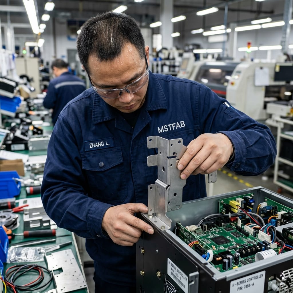
The 4 Rules for Setting Sheet Metal CTQ Dimensions
Follow these practical guidelines when assigning CTQ callouts to your CAD production drawings:
- The “Rule of 5”: A single sheet metal part should rarely have more than 3 to 7 CTQ dimensions. If you have 25 CTQs, you do not have a quality plan; you have an over-tolerancing problem.
- Always Establish Primary Datum Features on Flat, Pierced Surfaces: Never set your primary Datum A on a formed bend edge that fluctuates with springback. Establish Datum A on a flat laser-cut surface or precision pierced tooling hole.
- Use Maximum Material Condition (MMC) Callouts: When specifying hole patterns for fasteners, apply MMC modifiers (( M)). MMC provides bonus tolerance as hole sizes increase, dramatically lowering scrap while guaranteeing fastener clearance.
- Conduct Gage R&R on Measurement Fixtures: Ensure that the metrology tool used to measure the CTQ has a Measurement System Analysis (Gage R&R) error <10% of the total tolerance band.




Achieve Flawless Precision CTQ Sheet Metal Fabrication Consistency With MSTFAB
MSTFAB enforces ISO 9001 certified quality gates, CMM automated metrology, locked CNC bend sequences, and tamper-proof golden sample governance. Guarantee batch-to-batch repeatability from pilot run to mass production.
Frequently Asked Questions (FAQ)
How does designating CTQ dimensions lower manufacturing unit costs?
When a drawing has no CTQs, the fabricator assumes all 50 dimensions require slow, 100% CMM inspection and high-tonnage precision coining tooling, adding substantial labor and cycle time. By highlighting 4 key CTQs and assigning ISO 2768-m to the rest, the fabricator runs high-speed automated laser cutting and air-bending, slashing unit costs by up to 35%.
Can powder coat thickness cause a CTQ dimension to fail inspection?
Yes! Standard electrostatic powder coating deposits 60 to 120 microns (0.06 to 0.12mm) of cured polymer per side. If a CTQ hole diameter has a ±0.08mm tolerance, paint build-up will undersize the hole. Blueprints must explicitly specify: “Dimensions apply BEFORE powder coating” or include pre-paint CAD compensation allowances.
How does MSTFAB track CTQs during high-volume production?
At MSTFAB, designated CTQ features are entered into our automated shop-floor SPC software. Machine operators take sample measurements every 2 hours, entering data into touch terminals that automatically compute real-time Cpk trends, flagging tool wear before out-of-spec parts are ever produced.
 WeChat Contact
 WhatsApp Me Directly