
Quick answer: Medical OEM cosmetic panels and internal metal structures need different acceptance criteria. Exterior covers require defined appearance, edge condition, fit and cleaning compatibility. Internal chassis, mounting plates and brackets require controlled mounting interfaces, load paths and assembly access. Material grade alone does not establish disinfectant resistance, MRI suitability or medical-device compliance.
MSTFAB manufactures drawing-based sheet metal covers, panels, brackets, empty housings and agreed mechanical subassemblies. The OEM remains responsible for the completed device, including electronics, clinical performance, electrical safety, cleaning validation and regulatory approval. Confirm any special process, certification or test requirement before placing an order.

1. Separate cosmetic-panel requirements from chassis requirements
A front bezel can be dimensionally acceptable and still fail an agreed appearance standard. An internal support can look excellent and still misalign a pump or mounting rail. Use one controlled assembly drawing, but identify which features are cosmetic and which are functional.
- Exterior panels: mark visible faces, grain direction, coating color, texture, gloss, acceptable weld blending and inspection conditions. Set panel gaps and flushness relative to actual mating parts.
- Internal metal structures: identify mounting datums, hole patterns, installed hardware, payload locations and service access. State whether dimensions apply before or after finishing.
- Shared interfaces: review tolerance accumulation, hinge movement, latch engagement, coating buildup and assembly sequence. A CAD model should not be the only place a critical requirement appears.
2. Choose materials for the exposure and fabrication route
304 and 316L stainless steel: corrosion resistance is conditional
316L is a molybdenum-alloyed, low-carbon stainless grade and generally offers better chloride pitting resistance than 304 under comparable conditions. That is not immunity to bleach, salt deposits or crevice corrosion. PREN is a composition-based comparison tool, not a cleaning-compatibility approval or a universal service-life prediction.
It is incorrect to specify that 316L is mandatory wherever hospital bleach or saline is present. Grade selection depends on the actual chemical, concentration, temperature, contact time, rinsing, drying, finish and joint geometry. The British Stainless Steel Association’s hypochlorite guidance warns that these solutions can cause pitting and crevice corrosion, including in common stainless grades. Have the OEM approve the intended cleaning procedure and material/finish combination; this article is not a cleaning instruction.
5052-H32 and 6061-T6 aluminum: specify more than the alloy name
5052-H32 is often a practical candidate for formed covers. 6061-T6 can suit other structural or machined applications, but a bend radius must be checked for the selected temper, sheet thickness, bend angle, rolling direction, tooling and required surface quality. Neither a universal one-thickness radius for 5052 nor a universal 2.5-thickness radius for 6061 guarantees a sound cosmetic bend.
The Atlas Steels 5052 data sheet gives bending recommendations by temper and thickness, with a stated rolling-direction condition. Use material-specific data and a representative bend sample where appearance or cracking is critical. Specify flatness over a defined area and measurement condition; an alloy or tooling-plate trade name does not guarantee the flatness of a finished part.
Cold-rolled and coated steel: modulus is not a chassis acceptance test
Steel has a higher elastic modulus than aluminum, but this alone does not prove that an assembled chassis is three times stiffer or free of resonance. Panel span, section geometry, thickness, joints, supports and payload all matter. Flanges and stiffeners can improve stiffness, but there is no universal percentage improvement. Review cut-edge protection and finishing requirements for coated sheet, and obtain approval before substituting a different grade or thickness.

3. Treat MRI requirements and certification as separate decisions
Cold forming can increase the magnetic response of some austenitic stainless steels. The effect depends on alloy composition and processing, as explained by ASSDA’s magnetic-effects guidance. Do not assign a fixed permeability to every 304 or 316L fabricated part, or prescribe post-forming annealing from a field-strength number alone.
Changing to aluminum does not, by itself, establish MRI safety. The FDA’s MR testing and labeling guidance addresses device-level assessment. Material magnetism is only part of that assessment. Refer any MR application to the OEM’s responsible safety team; do not label a metal panel MR Safe based only on its grade.
For US device manufacturers, FDA’s revised Quality Management System Regulation became effective on February 2, 2026 and incorporates ISO 13485:2016 by reference. A generic sheet metal part does not automatically receive a device risk classification. This article is not evidence of supplier certification, FDA approval or completed-device compliance. Buyers should verify current certificates, their scope and project-specific quality requirements separately.
4. Define cosmetic appearance and cleaning compatibility
Terms such as “Class A,” “medical-grade finish” and “disinfectant resistant” are incomplete purchase specifications. Agree on visible-surface zones, lighting, viewing distance, inspection duration and an approved sample or documented defect limits. Specify color and gloss tolerances only where the measurement method and acceptance limits are defined.
For chemical compatibility, identify the exact cleaner or disinfectant and the OEM’s intended exposure conditions. Agree on the test specimen, finish system, exposure procedure and acceptable changes in appearance, adhesion or other relevant properties. A generic powder-coating description cannot establish resistance to every cleaner. No customer chemical-test results or guaranteed service life are claimed here.
State which edges need deburring or rounding, and identify handling surfaces and cable passages. Set the edge requirement to suit the design rather than applying an unverified radius to every feature. Mark bonding contact areas and masking requirements where specified; final electrical verification belongs in the OEM’s equipment validation plan.
5. Control mechanical interfaces without invented universal limits
Send the actual support locations, payload, allowable movement and operating conditions for internal structures. A simple beam equation does not represent every folded, welded or bolted chassis. The OEM’s design analysis or agreed testing must establish stiffness, transport and vibration acceptance criteria.
During fabrication review, check bend access, reliefs, hole proximity to bends, weld sequence, distortion risk and whether functional interfaces need a separate finishing operation. Select installed fasteners by exact part number, compatible sheet material, thickness and supplier installation data. Retention requirements cannot be inferred from thread size alone.
Do not grind hardware or welds flush merely for appearance unless the drawing permits it. Removing material can change retention or joint strength. Identify surfaces that must remain free of weld marks, and agree on any sample approval before repeat production.
6. Agree on evidence before the purchase order
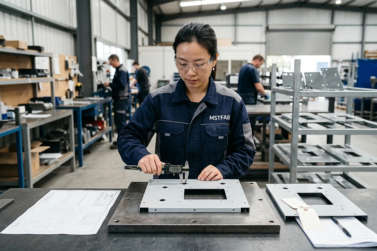
Use a project-specific inspection plan rather than a long list of unrelated standards. The checklist below identifies useful purchasing records; it is not a claim that every test or document is included in every order.
| Control point | Define before fabrication | Agree on the evidence |
|---|---|---|
| Released design | CAD and drawing revision, BOM, material grade and temper | Order acknowledgment referencing the approved revision |
| Appearance | Visible faces, finish specification, inspection conditions and sample | Approved sample reference and agreed appearance inspection record |
| Critical interfaces | Datums, tolerances, coating condition and free-state or restrained measurement | First-article results for the agreed features |
| Material and hardware | Required certificates, traceability level and hardware part numbers | Available material documents and agreed installation checks |
| Special performance | Chemical exposure, load, electrical or MR requirements and responsible party | OEM-approved test plan and applicable reports, not generic marketing claims |
| Delivery protection | Cleanliness, protective film compatibility, separation and identification | Agreed packing specification and pre-shipment photos if requested |
7. Protect finished panels without implying sterile delivery
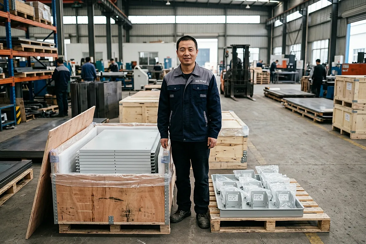
Review how visible faces, corners and installed hardware will be protected during handling and transport. Check that protective film or separators will not stain the finish or leave unacceptable adhesive residue. Mark part numbers and revisions so similar panels are not mixed during assembly.
Specify cleanliness and packaging requirements separately. Ordinary protective packaging is not sterile packaging, and a cleanroom air classification is not a residual-particle limit for a metal component. Any special cleaning, controlled-environment assembly or verification service requires an explicit feasibility review and written agreement.
8. Questions to settle before requesting a quote
Is 316L always necessary for a medical exterior cover?
No. Select the grade and finish against actual exposure, fabrication needs and the OEM’s acceptance criteria. A material label cannot replace cleaning-compatibility validation.
Can one tolerance cover both cosmetic and internal parts?
Not reliably. Identify appearance requirements separately from functional datums, mounting-hole locations and assembly fit. Excessively tight general tolerances can add cost without protecting a critical interface.
Does a first-article report prove medical-device compliance?
No. It records the agreed component checks. It does not replace device-level safety, performance or regulatory assessment.
What should an OEM send to MSTFAB?
Provide STEP files, controlled PDF drawings, BOM, quantities, material and finish requirements, cosmetic zones, critical interfaces and required records. Identify unusual chemical, cleanliness or MR conditions at the start. We can then review the mechanical fabrication scope and confirm which requirements can be included in the quotation.
Review our sheet metal fabrication scope or send medical panel and chassis drawings for review.
Scope boundary: This guide concerns fabricated mechanical parts, not complete medical devices. Illustrations are not customer project evidence, laboratory reports or proof of regulatory approval.
 WeChat Contact
 WhatsApp Me Directly