
BUILD-TO-PRINT MEDICAL ENCLOSURE METALWORK
Quick answer: PEM hardware DFM defines how buyer-specified self-clinching nuts, studs and standoffs interact with the enclosure sheet, forming sequence, finish and later mechanical assembly. MSTFAB fabricates empty medical equipment enclosure shells and drawing-defined hardware interfaces. We do not install electronics, wire devices, perform functional medical-equipment testing or certify a finished product.
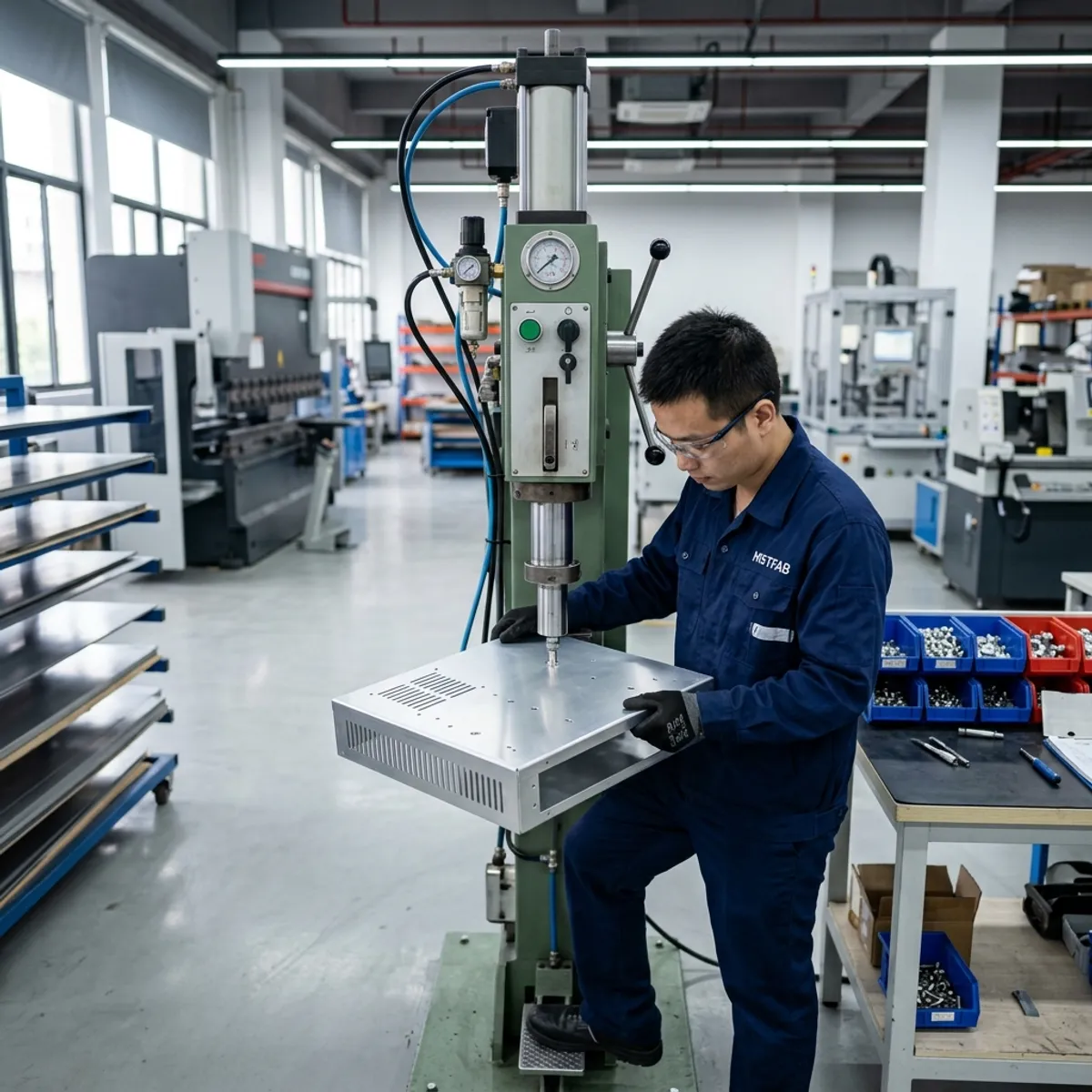
1. The smallest part can stop the largest assembly
A cabinet may contain kilograms of accurately cut and bent metal, yet one spinning threaded insert can stop the buyer’s assembly line. That is why self-clinching hardware belongs in sheet metal DFM, not in a last-minute purchasing note.
Empty bodies, covers, doors, chassis, mounting plates, brackets, cutouts, buyer-specified self-clinching hardware, weld studs, finishes, dimensional inspection and export packing.
PCBs, displays, sensors, wiring, electrical assembly, software, calibration, clinical validation, functional device testing and certification of completed medical equipment.
Hardware selection, mechanical loads, electrical architecture, approved vendors, component compliance, final assembly process, finished-product testing and certification.
This division keeps the metal supplier responsible for measurable metal and the product owner responsible for the finished device. It is less dramatic than arguing over a loose standoff after powder coating.
2. “M4 PEM nut” is not a complete specification
PEM is widely used as shorthand for self-clinching hardware, but different manufacturers and series have different installation requirements. The released drawing or BOM should identify the approved manufacturer, series, full part number, thread, material, finish and permitted alternatives.
The supplier’s current technical data should govern hole size, minimum sheet thickness, sheet-hardness limits, edge distance and installation force. A thread size tells the buyer what screw may fit. It does not tell production what hole the sheet needs.
Practical rule: control the exact hardware-to-sheet combination, not a generic cylinder in CAD.
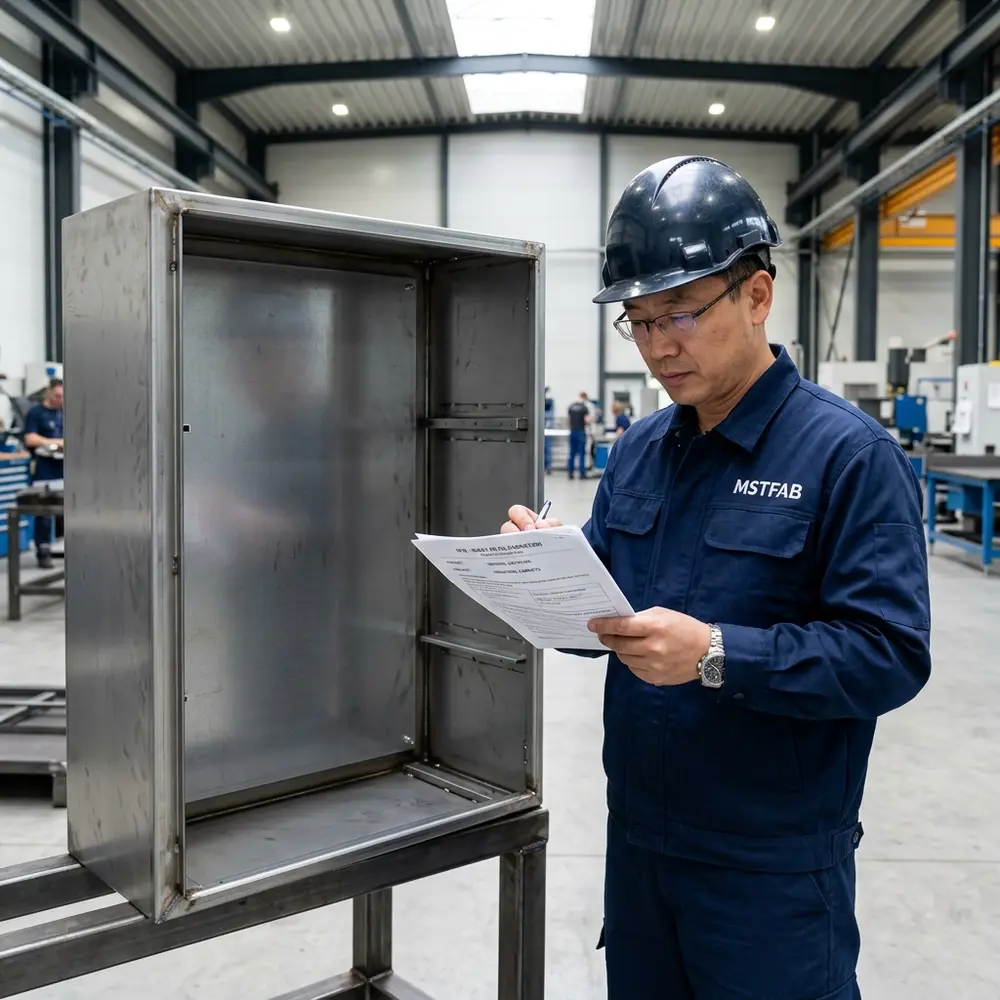
3. Choose the hardware family by function
Provide reusable internal threads in thin sheet where tool access may be available from one side during later assembly.
Provide an external threaded feature for brackets, covers or mating panels while reducing loose hardware.
Establish a controlled mechanical height for plates, PCBs or buyer-installed modules.
Rivet nuts, weld nuts and weld studs use different installation processes and should not be treated as automatic substitutes.
Choose by sheet material, thickness, access, load direction, service cycles and cosmetic condition. One fastener family is not a universal answer merely because it worked on the previous cabinet.
4. Match hardware to sheet thickness and hardness
Self-clinching hardware retains by displacing sheet material into the fastener’s locking features. The sheet must be thick enough and sufficiently softer than the hardware for that mechanism to work as intended.
Cold-rolled steel, galvanized steel, stainless steel and aluminum may require different series or material combinations. Review the actual temper and hardness, not only the alloy name. Stainless steel has a particular talent for exposing assumptions that survived perfectly well in mild steel.
5. Treat the installation hole as a critical feature
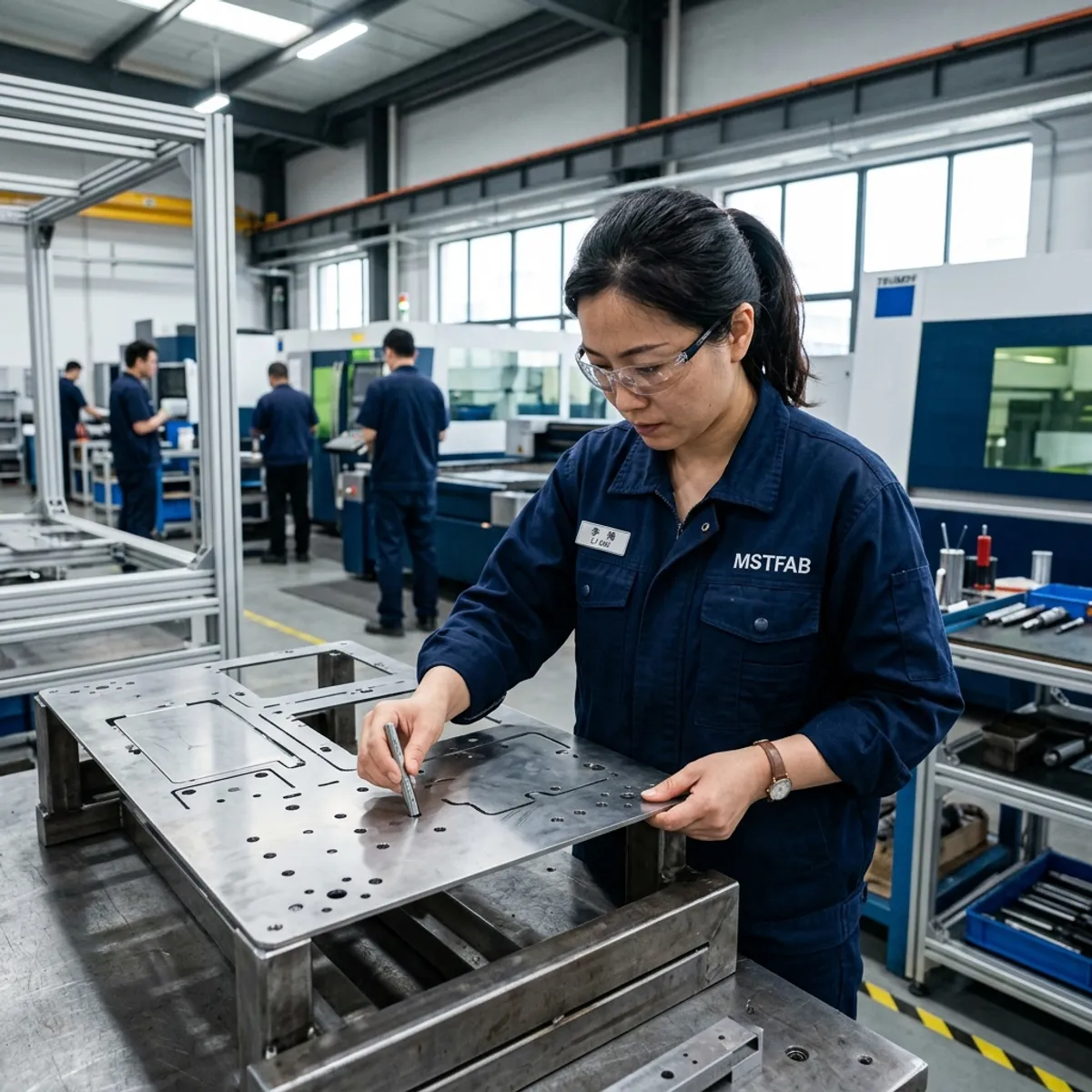
The installation hole controls how material flows around the fastener. Check diameter, roundness, burr direction, taper and local flatness. If the hole is oversized, retention may fall. If it is undersized or heavily burred, installation can distort the sheet or damage the hardware.
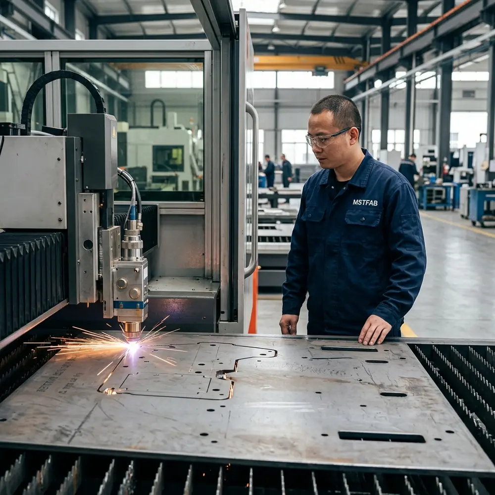
Laser cutting may be suitable for many features, but small holes in thicker material or tightly controlled installations may need drilling, reaming or another agreed secondary operation. The drawing should define the finished hole requirement and inspection method.
6. Respect edge distance and local deformation
During installation, material moves around the fastener. Hardware too close to a free edge, cutout or narrow web can bulge the panel, split the edge or reduce retention. Use the selected supplier’s minimum distances and add application margin where cosmetic or load risk justifies it.
Moving a hole a few millimetres in CAD is cheap. Moving it after 300 finished panels arrive is an advanced procurement workshop with unusually poor refreshments.
7. Hardware near bends needs a process plan
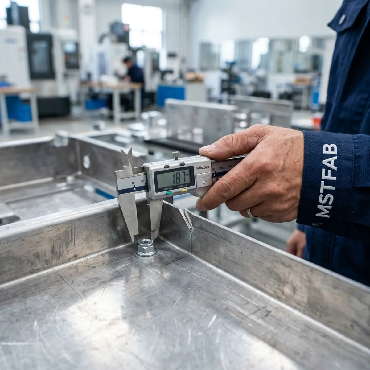
A fastener near a bend creates two access questions. If installed before forming, will it collide with the punch, die or back gauge? If installed after forming, can the installation press reach the hole without crushing the flange?
Also consider the bend deformation zone. Hole-to-bend distance, inside radius, flange length and material springback can change local geometry. Define whether the critical position is measured in the flat or formed condition; for assembly, the formed condition usually wins.

8. Define installation side, orientation and access
The drawing should show which side receives the fastener and which direction the thread or stud projects. For concealed or cosmetic surfaces, identify the acceptable witness mark and the surface that must remain flush.
Do not assume the shop will infer direction from a shaded CAD view. A mirrored insert can be dimensionally impressive and completely unavailable to the buyer’s screwdriver.
9. Control standoff height as an assembled stack
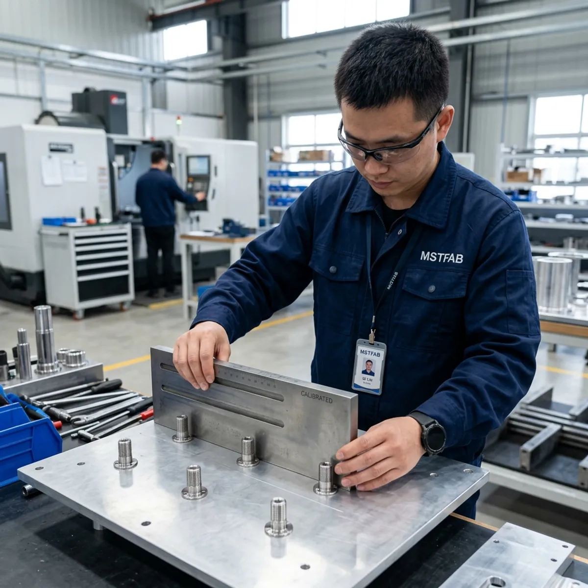
A standoff interface includes more than the nominal hardware length. Sheet thickness, installation seating, coating, mating-part flatness and screw engagement all affect the finished stack.
Define installed height, permissible tilt, thread engagement and the functional mating pattern. When several standoffs support one plate, check coplanarity or fit with a buyer-approved dummy so one tall feature does not turn the assembly into a small metal table with a short leg.
10. Keep cosmetic surfaces in the discussion
Installation force can leave a witness mark, ring or local dish on the opposite face. That may be acceptable inside a chassis and unacceptable on a visible medical-equipment panel. Mark Class-A surfaces and agree on the acceptable appearance before production.
Where cosmetic risk is high, the design may need more sheet thickness, a different fastener series, a concealed bracket or another fastening method. There is no inspection method capable of measuring “looks premium” unless the parties first define what that means.
11. Put coating and masking instructions on the drawing
Powder coating can fill threads, change standoff seating, cover identification marks and affect electrical-contact areas. State which threads need plugs, which studs need caps, which surfaces require masking and whether the hardware is installed before or after finishing.
Hardware finish and sheet finish should also be compatible with the buyer’s corrosion, appearance and cleaning requirements. MSTFAB manufactures to the released mechanical specification; the buyer approves suitability for the final device environment.
If a thread is important but the masking note is missing, powder will find it. Powder coating is diligent that way.

12. Do not merge fastening hardware with protective-earth design
A threaded insert used to mount a bracket is not automatically an approved protective-earth connection. Grounding and bonding require their own material, contact-surface, masking, hardware, inspection and final electrical-validation decisions.
Keep that topic in its own controlled interface. The separate medical enclosure protective-earth interface DFM guide explains the mechanical information MSTFAB needs for grounding studs and contact areas without turning this article into a second grounding page.
13. Define retention requirements without inventing test values
Push-out, pull-through and torque-out capability depend on the exact hardware, sheet material, thickness, hole preparation and installation setting. The buyer should state the functional load or approved supplier requirement and identify whether lot testing, sample testing or certification data is needed.
MSTFAB should not guess a torque value from the screw size. A confident number pulled from the air is still air. Use approved technical data and project-specific acceptance criteria.
14. Use mechanical mating checks where patterns matter
Coordinate measurements are useful, but a controlled template, dummy bracket or non-powered sample can verify the finished pattern, standoff height and assembly access in one step. The gauge needs a part number, revision and defined acceptance method.
This remains a mechanical fit check. MSTFAB does not install electronics or perform powered functional testing.
15. Control substitutions and revision changes
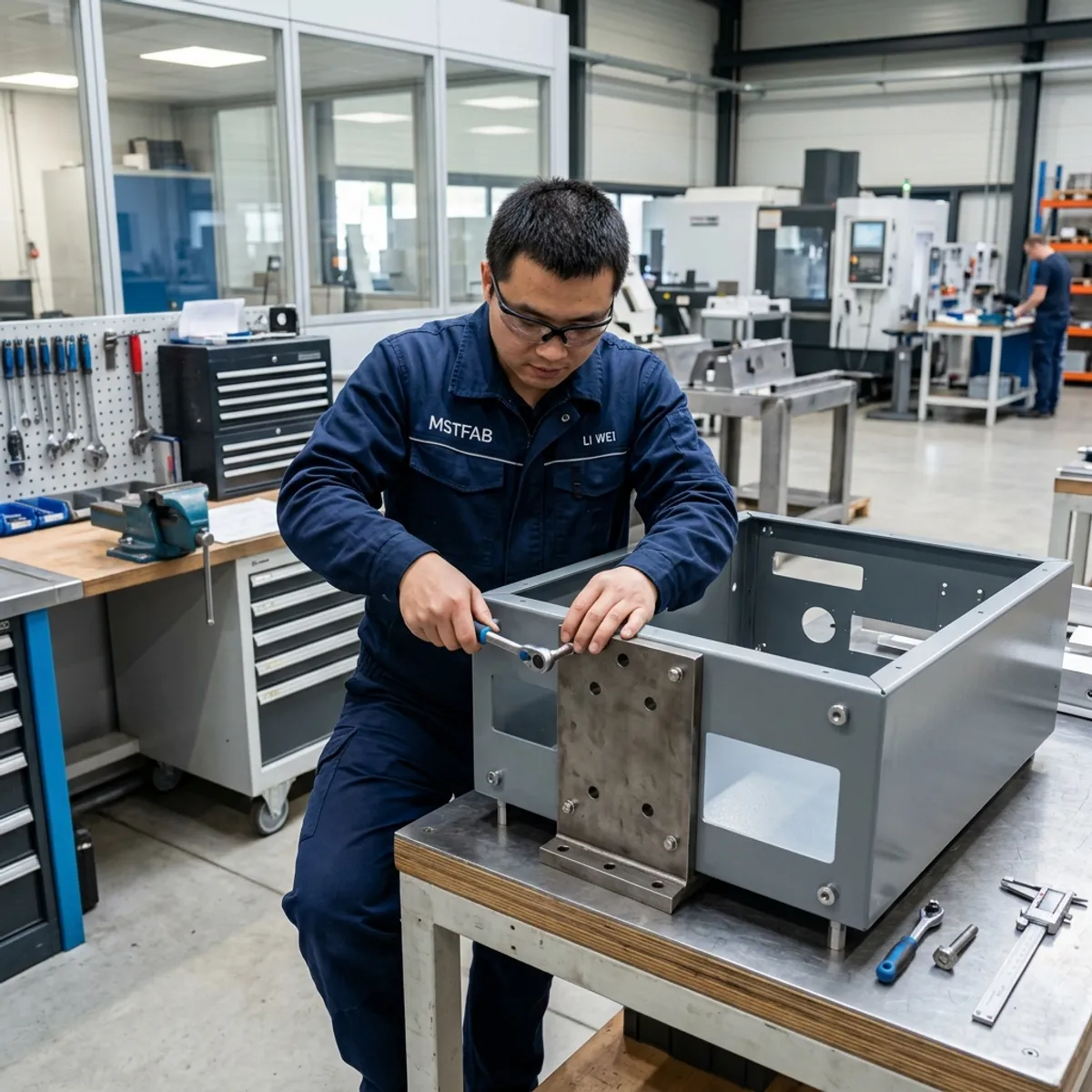
A substitute fastener may share the same thread and still require a different hole, sheet thickness, hardness or installation tool. Define approved alternatives in the BOM or require buyer approval before substitution.
Revision control should connect the enclosure drawing, hardware BOM, installation instruction, inspection plan and packing label. Otherwise the factory can build the new panel with the old fastener and create a problem that is technically well documented in two different places.
16. Agree on first-article evidence
| Feature | Useful control | Evidence |
|---|---|---|
| Hardware identity | Approved manufacturer and part number | BOM, packing label or traceability record |
| Installation hole | Finished diameter and edge condition | Dimensional inspection record |
| Position and side | Functional datums and orientation note | Drawing report and visual check |
| Height and alignment | Installed condition and mating pattern | Height check, template or dummy fit |
| Retention | Buyer-approved sample plan and limits | Push-out or torque-out result when required |
| Finish protection | Masking and cosmetic-surface notes | Final visual and thread inspection |
17. Responsibility matrix
| Item | MSTFAB mechanical scope | Buyer or product-owner scope |
|---|---|---|
| Shell and hardware features | Fabricate and install to released drawings | Approve geometry and intended function |
| Hardware selection | Review manufacturability and availability | Approve part number, load and permitted substitutes |
| Mechanical verification | Perform agreed dimensional, fit or retention checks | Define acceptance criteria and final assembly needs |
| Electronics and wiring | Not supplied or installed | Select, install, test and validate |
| Finished medical equipment | No functional or clinical certification | Own product safety, regulatory work and certification |
18. RFQ checklist for fewer loose ends
- Controlled enclosure STEP file
- Released 2D drawings
- Hardware manufacturer and part number
- Approved alternatives or no-substitution note
- Sheet material, temper and thickness
- Hole size and edge condition
- Edge and bend clearances
- Installation side and sequence
- Installed height and mating pattern
- Mechanical load or approved test criteria
- Finish, masking and cosmetic notes
- FAI, traceability and packing requirements
Frequently asked questions
Does MSTFAB supply completed medical equipment?
No. MSTFAB fabricates buyer-designed empty sheet metal shells and mechanical parts. The buyer owns electronics, wiring, software, functional testing, regulatory work and finished-product certification.
Is “M4 PEM nut” enough for a quotation?
No. Provide the approved manufacturer, series and full part number together with sheet material and thickness. Similar thread sizes can require different installation details.
Can self-clinching hardware be installed before powder coating?
Often yes, but the drawing must define thread masking, contact areas, cosmetic requirements and whether the selected hardware finish is compatible with the finishing process.
Can MSTFAB verify hardware without installing electronics?
Yes. Dimensional inspection, controlled templates, mechanical dummies and agreed retention tests can verify the metal interface without powered devices.
Send the exact fastener, not a mysterious CAD cylinder
Share the enclosure assembly, controlled drawings, hardware BOM, sheet specification, finish, quantity and critical acceptance criteria. MSTFAB will review the build-to-print hardware interfaces and return practical DFM questions before production.
 WeChat Contact
 WhatsApp Me Directly