
⚡ Direct Answer: How to Evaluate Industrial Electronics Enclosure Suppliers?
Evaluating industrial electronics enclosure suppliers requires auditing six core engineering and manufacturing competencies: 1) Precision PCB & Component Interface DFM (automated PEM fastener insertion maintaining true position tolerances within ±0.05 mm across multi-board mother-daughter arrays); 2) Dynamic Thermal Management Engineering (optimizing louver free-area ratios and forced-convection fan CFM airflow pathways to prevent internal electronic hot-spots); 3) Electromagnetic Compatibility (EMC / EMI Shielding) (integrating continuous conductive seams, beryllium-copper fingerstock, or Form-in-Place conductive silicone gaskets providing > 60 dB attenuation from 30 MHz to 10 GHz); 4) Environmental Ingress Protection (IP65, IP66 & NEMA 4X) (precision knife-edge gasket lands with CNC-dispensed continuous polyurethane foam gaskets); 5) Certified Military & Industrial Surface Finishing (in-house 5-stage automated conversion pretreatment, MIL-DTL-5541 chromate conversion, and Qualicoat Class 2 superdurable powder coatings with precision thread/ground masking); and 6) Full Supply Chain Traceability & Metrology (Zeiss Bridge CMM dimensional reports, AS9102 First Article Inspection documentation, EN 10204 Type 3.1 material certificates, and rapid 5-day prototyping ramping to high-volume blanket PO releases).
Table of Contents: Industrial Electronics Enclosure Sourcing & Engineering Guide
- 1. The Strategic Role of Custom Sheet Metal Electronics Enclosures
- 2. Enclosure Form Factors: 19-Inch Rackmount, Wall-Mount, Desktop & DIN-Rail Systems
- 3. Thermal Management DFM: Calculating Required Fan Airflow (CFM) & Louver Sizing
- 4. EMI / RFI Shielding Architecture: Slot Antennas, Gasketing & Surface Conductivity
- 5. Environmental Ingress Sealing: Engineering NEMA 4, 4X, IP65 & IP66 Enclosures
- 6. PCB Mounting Standoffs, Clinching Hardware & Subassembly Integration
- 7. Material Selection Matrix: 5052-H32 Aluminum vs. Carbon Steel vs. 304/316L Stainless
- 8. Precision Sheet Metal Fabrication Workflow: Laser Piercing to Robotic Welding
- 9. Surface Pretreatment, Powder Coating & Precision Masking Protocols
- 10. Supplier Audit Matrix: 10 Critical Competencies & Warning Red Flags
- 11. Failure Mode & Effects Analysis (FMEA): 6 Common Enclosure Field Breakdowns
- 12. Engineering Case Study: High-Performance Industrial IoT Edge Computing Chassis
- 13. Electrical Grounding, Bonding & Safety Standards (UL 508A & IEC 62368-1)
- 14. Shock, Vibration & Seismic DFM: MIL-STD-810H & IEC 60068-2-6
- 15. Computational Fluid Dynamics (CFD) & Fan Operating Point P-Q Curves
- 14. OEM Sourcing Checklist & RFQ Specifications for Electronics Metalwork
- 15. Comprehensive Engineering FAQs on Industrial Electronics Enclosures
1. The Strategic Role of Custom Sheet Metal Electronics Enclosures
Inside modern factory automation, telecommunications networks, renewable energy inverters, and edge-computing infrastructure, the metal enclosure is far more than a cosmetic external skin. It is an active electro-mechanical subsystem that directly determines product lifespan, operational reliability, regulatory certification success, and user safety.
While early-stage hardware prototypes often utilize off-the-shelf catalog plastic boxes or generic extruded aluminum enclosures, commercial-scale OEMs rapidly encounter severe technical and economic roadblocks with catalog enclosures:
- Sub-Optimal Internal Packaging Density: Standard off-the-shelf boxes force engineers to compromise PCB layout, heat sink placement, and cable routing to fit generic internal bosses, resulting in wasted volume and oversized products.
- Expensive Secondary Machining Operations: Modifying off-the-shelf catalog boxes requires secondary CNC milling of connector cutouts, display windows, and cable glands. Post-machining exposed raw edges strips protective coatings, introduces burrs, voids IP sealing ratings, and adds 15 to40 per unit in secondary handling costs.
- Thermal Dissipation Bottlenecks: Plastic enclosures act as thermal insulators (kappaplastic ≈ 0.2W/m·K), trapping heat generated by high-power microprocessors, MOSFETs, and power transformers. Custom sheet metal enclosures fabricated from aluminum (kappaaluminum ≈ 138W/m·K) act as massive heat spreaders, transferring internal heat directly to ambient air.
- Severe Tooling Lead Times of Die-Casting: Aluminum die-casting requires expensive steel injection molds costing 25,000 to80,000 with 12 to 16-week lead times. If a PCB revision shifts an I/O port by just 2 mm, the entire die-cast mold must be scrapped. Custom CNC sheet metal fabrication requires zero hard tooling, allowing design revisions to be deployed in CAD within minutes.
2. Enclosure Form Factors: 19-Inch Rackmount, Wall-Mount, Desktop & DIN-Rail Systems
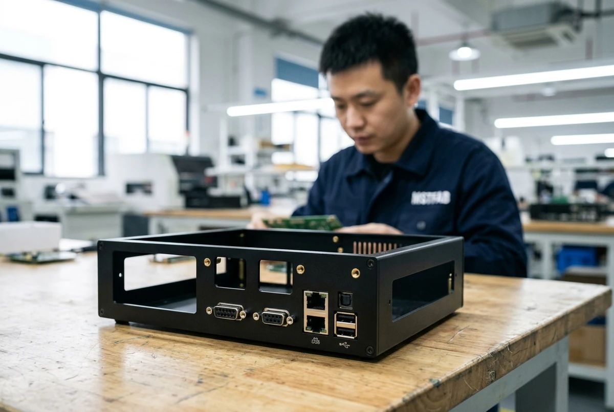
Industrial electronics equipment must fit standardized physical deployment architectures. MSTFAB manufactures custom sheet metal enclosures across four primary architectural configurations:
1. 19-Inch Rackmount Chassis (EIA-310-E Standard)
The global standard for data center servers, broadcast consoles, telecommunication hubs, and industrial instrumentation racks. Rack units are measured in standard “U” multiples (1U = 1.75 inches = 44.45 mm):
- 1U and 2U Shallow & Deep Draw Chassis: Fabricated from 1.2 mm to 1.5 mm cold-rolled steel or 5052-H32 aluminum. Features reinforced front mounting flanges (ears) with standardized oval EIA mounting slots, telescopic chassis slide-rail mounting holes, and internal card-cage divider baffles.
- 3U to 6U High-Capacity Industrial Servers: Utilizes an internal welded or riveted sub-chassis skeleton carrying hot-swappable power supply cages, modular fan trays, and multi-drive backplanes, enclosed by removable top, bottom, and side cosmetic panels.
2. Wall-Mount NEMA / IP Industrial Control Cabinets
Engineered for mounting on factory walls, machine structural columns, or outdoor utility poles. These enclosures feature a continuous seam-welded body, formed knife-edge door frames, internal galvanized mounting sub-panels (gear plates) for mounting PLCs and contactors, and external heavy-gauge mounting tabs that allow wall installation without penetrating the sealed electrical interior.
3. Desktop & Benchtop Instrument Enclosures
Designed for laboratory diagnostic devices, medical monitors, and precision test equipment. Configurations include:
- Sloped Front Consoles: Ergonomic 15° to 45° inclined front faceplates designed for capacitive touchscreen displays, membrane switches, and rotary dials.
- Two-Piece Clamshell Enclosures: Top and bottom interlocking U-shaped sheet metal covers that slide together and fasten along the sides, providing 360° internal accessibility during assembly and testing while hiding fasteners from the front cosmetic view.
4. Modular DIN-Rail Mount Split Enclosures
Compact sheet metal housings designed to snap directly onto standardized 35 mm DIN rails (EN 50022) inside industrial automation control cabinets. MSTFAB integrates rear-formed spring-loaded snap clips and internal PCB guide rails, replacing fragile plastic DIN housings in high-vibration railway and heavy machinery applications.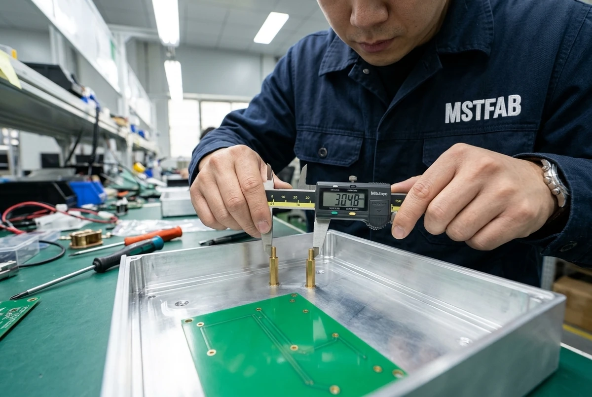
3. Thermal Management DFM: Calculating Required Fan Airflow (CFM) & Louver Sizing
Modern industrial computing and power electronics dissipate significant heat within enclosed volumes. Every 10° C increase in internal component operating temperature reduces semiconductor life expectancy by approximately 50% (Arrhenius equation). Proper enclosure design must actively manage heat dissipation.
Thermal Airflow Calculation (Forced Convection)
To size cooling fans and ventilation openings for forced-air cooling, mechanical engineers calculate the required volumetric airflow rate (Qair in Cubic Feet per Minute – CFM) using the thermodynamic energy balance equation:
Where:
- Qtotal: Total internal heat dissipation generated by internal electronics, power supplies, and processors (Watts).
- Δ Tallowed: Maximum permissible internal air temperature rise above external ambient temperature (Tinternal – Tambient in °C).
- $1.76: Thermodynamic conversion constant factoring the specific heat capacity and sea-level density of standard dry air.
Engineering Example: 350W Industrial Control Chassis
Consider an industrial edge server dissipating Qtotal = 350Watts installed in a factory plant floor where maximum ambient temperature reaches Tambient = 40° C. To protect sensitive microprocessors, internal air temperature must not exceed Tinternal ≤ 55° C (Δ T = 15° C):
Factoring an internal static pressure loss multiplier (kbackpressure ≈ 1.50 accounting for internal cable bundles, PCBA flow impedance, and intake dust filters), the total required fan capacity is:
| Thermal Strategy | Max Heat Dissipation (Q) | Ingress Protection Capability | MSTFAB Sheet Metal DFM Features |
|---|---|---|---|
| Natural Convection (Passive) | ≤ 50 W / m² surface area | IP20 – IP30 (Vented) or IP66 (Sealed) | Formed louver patterns, high-emissivity black anodize, extruded aluminum heat sinks. |
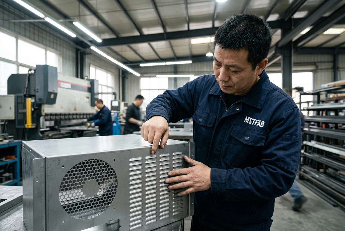
| Forced Air Fan Trays (Filtered) | 50 W – 800 W | IP54 / NEMA 12 (With Gasket Filters) | Hexagonal honeycomb perforated patterns (> 63% open area), quick-change filter slide-frames. |
| Closed-Loop Air Conditioners | 500 W – 5,000 W+ | IP65 / IP66 / NEMA 4X Sealed | Precision side-cutout mounting flanges, reinforced door stiffeners, internal drip baffles. |
| Direct Liquid Cold Plate Loops | 1,000 W – 15,000 W | IP66 / NEMA 4X (Sealed Chassis) | Bulkhead quick-disconnect fluid fittings, leak containment drip trays with gravity weep drains. |
4. EMI / RFI Shielding Architecture: Slot Antennas, Gasketing & Surface Conductivity
Industrial electronics must comply with strict Electromagnetic Compatibility (EMC) regulations, including FCC Part 15 Subpart B (Class A/B) in North America and EN 55032 / EN 61000-6-2/4 in Europe. Unshielded enclosures allow high-frequency switching noise from power converters and microprocessors to radiate outwards, while exposing internal circuits to external electrostatic discharges (ESD) and radio frequency interference.
The Slot Antenna Effect: Cutout DFM
Electromagnetic radiation does not leak through solid sheet metal; it escapes through gaps, seams, and ventilation cutouts. Any seam or slot in a metal enclosure behaves as a resonant slot antenna. To maintain at least 40 dB to 60 dB shielding attenuation, the maximum allowable linear slot dimension (Lmax in mm) must not exceed one-twentieth of the wavelength (lambda) of the highest internal operating frequency (fmax):
Where c ≈ 3 × 10^8m/s (speed of l). For a system with internal switching harmonics reaching fmax = 2.4GHz (such as embedded Wi-Fi / Bluetooth IoT modules or clock harmonics):
Any seam or laser cutout longer than 6.25 mm will freely radiate 2.4 GHz energy! For this reason, large rectangular cooling holes are strictly avoided in favor of dense hexagonal honeycomb perforation arrays where each individual aperture diameter is ≤ 4.0mm.
Conductive Gasketing & Surface Continuity
- Beryllium Copper (BeCu) Fingerstock: Provides the highest shielding effectiveness (> 100 dB attenuation) across removable chassis covers and sliding rack trays. High spring fatigue life withstands thousands of open/close cycles without permanent deformation.
- Conductive Silicone / Fluorosilicone Gaskets: Elastomers filled with silver-plated aluminum, nickel-graphite, or copper micro-particles provide simultaneous environmental IP65 sealing and EMI shielding.
- Chemical Conversion Coating (MIL-DTL-5541 Type II Class 3): Standard anodizing creates an electrical insulating aluminum oxide layer (Al_2O_3) that destroys EMI grounding. MSTFAB applies RoHS-compliant trivalent chromium conversion coatings (SurTec 650 or Alodine 5200) that preserve low surface contact resistance (Rsurface < 5mΩ) across all mating seams.
5. Environmental Ingress Sealing: Engineering NEMA 4, 4X, IP65 & IP66 Enclosures
Outdoor, washdown, and dusty industrial environments demand certified Ingress Protection (IP) per IEC 60529 and NEMA ratings per NEMA 250. The table below outlines design rules for achieving watertight and dust-tight performance:
Ingress Protection Architecture Comparison
| Rating | Solid Protection | Liquid Protection | Enclosure Sealing Architecture |
|---|---|---|---|
| IP54 / NEMA 12 | Dust Protected | Water splashing from any angle | Single-bend perimeter return flange; filtered fan ventilation. |
| IP65 / NEMA 4 | Dust-Tight (Vacuum tested) | Water jets (12.5 L/min at 30 kPa) | Continuous seamless FIP polyurethane foam gasket; welded seams. |
| IP66 / NEMA 4X | Dust-Tight (Vacuum tested) | Heavy seas & powerful jets (100 L/min at 100 kPa) | Double-labyrinth formed door channel; 304/316L stainless or C5-M powder coat. |
| IP67 / NEMA 6 | Dust-Tight (Vacuum tested) | Temporary immersion (1.0 meter for 30 minutes) | Milled O-ring tongue-and-groove channel; high-torque perimeter clamping fasteners. |
Formed Knife-Edge & Gasket Compression Dynamics
Under-compressing an elastomeric gasket results in liquid bypass channels; over-compressing exceeds the elastomer’s elastic recovery limit, causing permanent compression set and seal failure. MSTFAB incorporates precision brake-formed 90° knife-edge door flanges that contact the center of the gasket channel. When the door latches are engaged, the knife-edge achieves optimal 25% to 30% nominal gasket deflection, concentrating clamping pressure along a narrow sealing line while internal mechanical door stops prevent over-compression.
6. PCB Mounting Standoffs, Clinching Hardware & Subassembly Integration
Printed Circuit Boards (PCBs) must be rigidly secured inside the enclosure without bowing or mechanical strain that would crack surface-mount ceramic capacitors (MLCCs) or solder ball arrays (BGAs).
Fastener Selection & True Position Tolerance
- Self-Clinching Standoffs (PEM Type SOSG / TSO): Installed via automated hydraulic presses into precision laser-cut pilot holes. Standoff heights are held within ±0.05 mm, ensuring that all mounting bosses across a multi-board plane lie in the exact same mathematical datum plane, preventing board warping upon screw torquing.
- Thread-Release & Blind Standoffs: In NEMA 4X and IP66 enclosures, through-hole threaded standoffs breach the outer weather skin. MSTFAB utilizes blind self-clinching standoffs (PEM Type B) that embed into the inner sheet metal surface, leaving the exterior face completely smooth, puncture-free, and watertight.
- Floating Self-Clinching Fasteners (PEM Type AS / AC): For large backplanes or multi-bay card cages where thermal expansion causes minor dimensional shift, floating nuts allow up to 0.8 mm of radial float, compensating for manufacturing tolerance stack-ups without binding.
7. Material Selection Matrix: 5052-H32 Aluminum vs. Carbon Steel vs. 304/316L Stainless
Selecting the correct raw metal alloy balances structural stiffness, overall unit weight, thermal conductivity, environmental corrosion resistance, and manufacturing economics:
| Material Alloy | Density (ho) | Thermal Conductivity (kappa) | Corrosion Resistance | Best Practical Application |
|---|---|---|---|---|
| Aluminum 5052-H32 | 2.68 g/cm³ (Lightwe) | 138 W/m·K (Superior) | High (Immune to rust) | Premium Choice: Rackmount servers, edge computers, avionics, mobile systems. |
| Cold Rolled Steel (SPCC / A1008) | 7.85 g/cm³ (Heavy) | 50 W/m·K | Low (Requires paint) | Cost-sensitive indoor automation cabinets, high-rigidity structural framework. |
| Galvanized Steel (SECC / SGCC) | 7.85 g/cm³ | 52 W/m·K | Moderate (Sacrificial zinc) | Unpainted internal gear plates, server chassis sub-frames, telecom power shelves. |
| Austenitic Stainless 304 / 316L | 7.93 g/cm³ | 16 W/m·K (Poor) | Extreme (C5-M Marine) | NEMA 4X washdown enclosures, food/beverage processing, chemical marine terminals. |
8. Precision Sheet Metal Fabrication Workflow: Laser Piercing to Robotic Welding
At MSTFAB, high-reliability industrial electronics enclosures are fabricated on automated CNC production cells adhering to ISO 9001:2015 quality standards:
- 15kW High-Speed Fiber Laser Cutting: Blanks are profiled using 99.999% pure nitrogen assist gas. Micro-piercing parameters prevent thermal distortion around dense D-sub, HDMI, and RJ45 I/O port arrays, holding true position within ±0.05 mm.
- Multi-Head Automated Rotary Brush Deburring: Blanks pass through oscillating abrasive brush heads that round all interior cutout edges and outer contours to a uniform radius (R ≥ 0.5mm to 1.0mm), guaranteeing zero razor-sharp edges that could cut assembly wiring.
- 7-Axis Electric Servo CNC Press Brake Bending: High-precision electric press brakes equipped with laser angle-measuring systems verify bend angles in real-time. Custom-ground urethane-lined tooling prevents tool marks on pre-finished aluminum and stainless steel panels.
- Robotic TIG & Cold Metal Transfer (CMT) Seam Welding: Corner seams are welded on dedicated modular 3D fixturing tables. Fronius CMT welding reduces heat input by up to 60%, preventing thin-gauge sheet metal warping and holding overall enclosure squareness within ±0.5 mm across diagonal dimensions.
- Automated Hardware Clinching with Monitored Hydraulic Force: Precision PEM hardware installation machines insert self-clinching standoffs and grounding studs with digitally logged press tonnage and dwell time, ensuring 100% repeatable push-out and torque-out resistance.
9. Surface Pretreatment, Powder Coating & Precision Masking Protocols
Industrial electronics enclosures operate in harsh industrial environments exposed to humidity, chemical fumes, and lubricating oils. A flawed surface finish results in premature corrosion and catastrophic electrical grounding failure.
The 5-Stage Automated Chemical Pretreatment Process
Prior to powder coating, all sheet metal parts undergo an automated 5-stage chemical pretreatment wash:
- Alkaline spray degreasing to remove forming lubricants and oils (55° C).
- High-purity reverse-osmosis water rinse.
- Micro-etching acid bath to clean oxides and expose active metal grain.
- Zirconium nanocoating / non-chrome trivalent chemical conversion (establishing microscopic mechanical adhesion).
- Final deionized water halo rinse and automated drying oven dehydration (120° C).
Qualicoat Class 2 / AAMA 2604 Superdurable Powder Coating
MSTFAB applies architectural-grade TGIC-free polyester powder coatings cured at 200° C, achieving a uniform dry film thickness (DFT) of 70 µm to 100 µm. The coating delivers superior UV gloss retention, chemical resistance against industrial solvents, and withstands over 1,500 hours of ASTM B117 salt spray corrosion testing without blister creep.
Precision Masking Protocols
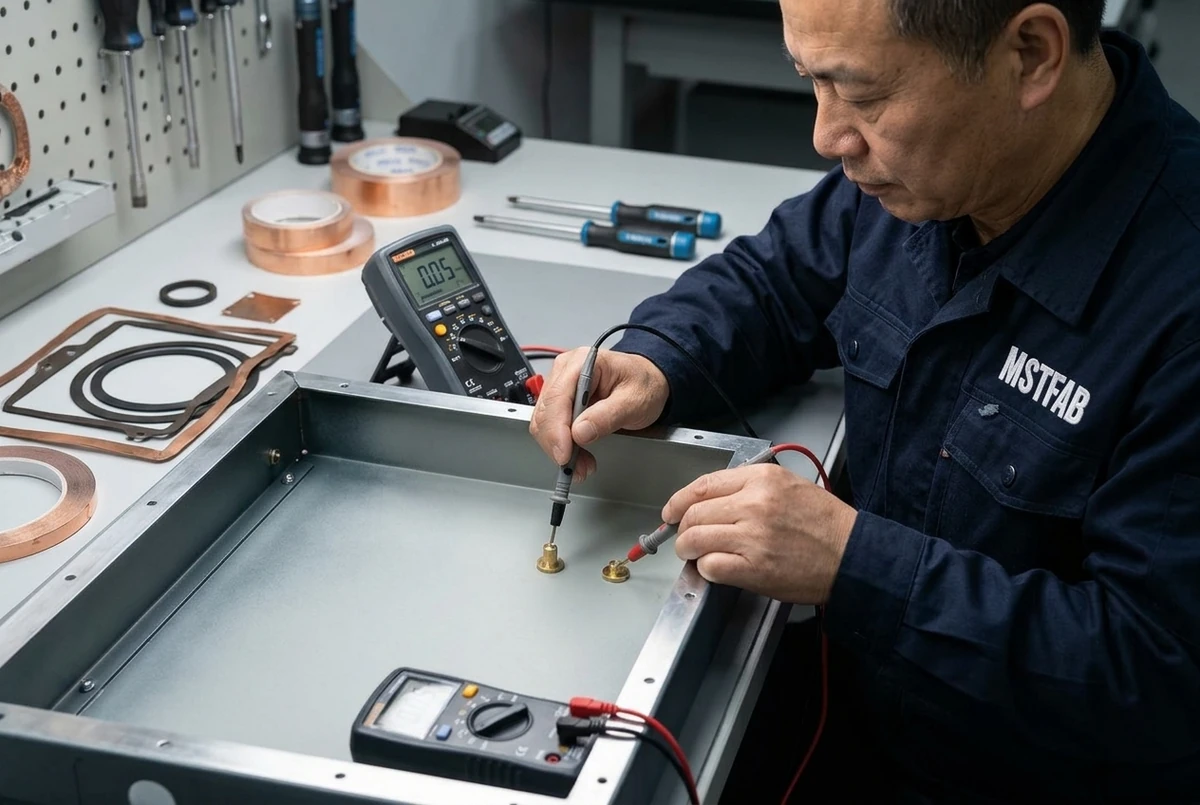
Powder coating is a dielectric electrical insulator. If powder penetrates threaded standoffs or covers grounding contact areas, the chassis loses electrical bonding, causing immediate failure during factory hipot and continuity testing. MSTFAB uses custom-engineered high-temperature silicone pull-plugs and die-cut Kapton masking dots to protect internal threads, grounding bosses, and EMI gasket land areas, guaranteeing 100% bare metal conductivity where required.
10. Supplier Audit Matrix: 10 Critical Competencies & Warning Red Flags
When evaluating contract sheet metal manufacturers for high-reliability electronics enclosures, procurement teams should utilize the following 10-point technical audit checklist:
| Audit Area | World-Class Supplier Standard (MSTFAB) | Warning Red Flag (Unqualified Shop) |
|---|---|---|
| 1. Laser Cutting Technology | 15kW fiber laser with automated pallet changers; nitrogen assist. | Legacy CO2 laser with oxygen assist causing heavy dross and oxide edges. |
| 2. Edge Deburring | Automated multi-head rotary brush deburring (R ≥ 0.5mm). | Hand angle-grinders leaving uneven gouges and sharp internal corners. |
| 3. CNC Bending Precision | Multi-axis electric press brakes with real-time laser angle sensors (±0.2°). | Manual hydraulic brakes with manual hand-crank backgauges. |
| 4. Hardware Clinching | Automated hydraulic PEM presses with digital tonnage logging. | Manual arbor press or hammer-set hardware with unpredictable retention. |
| 5. Gasket Dispensing | 6-axis CNC robotic Form-in-Place (FIP) polyurethane foam dispensing. | Manually cut rubber strip gaskets with overlapping leaky corner joints. |
| 6. Surface Finishing | In-house automated 5-stage pretreatment and conveyorized powder coating. | Outsourced painting causing 2-week delays and zero quality accountability. |
| 7. Thread Masking | Engineered silicone plugs and die-cut Kapton dots; 100% thread gauge verification. | Paint overspray inside threads forcing OEM assembly line thread tapping. |
| 8. Metrology Inspection | Zeiss Bridge CMM and FaroArm 3D scanning; AS9102 FAI report documentation. | Manual tape measures and basic vernier calipers without calibration logs. |
| 9. Material Traceability | EN 10204 Type 3.1 Mill Test Reports (MTR) tracked per production heat lot. | Secondary market scrap metal without chemical composition certs. |
| 10. Prototyping to Volume | 5-day rapid pilot prototyping ramping to scheduled annual blanket releases. | Long 6-week prototype turnaround with no volume production scalability. |
11. Failure Mode & Effects Analysis (FMEA): 6 Common Enclosure Field Breakdowns
Proactive risk management prevents expensive assembly line delays and field warranty recalls. MSTFAB applies Design and Process FMEA protocols across every customer program:
| Failure Mode | Root Mechanical Cause | Severity | MSTFAB Sheet Metal DFM Countermeasure |
|---|---|---|---|
| 1. PCB Standoff Coordinate Misalignment | Bend tolerance stack-up shifting hole pitch by > 0.4 mm across multiple sheet folds. | Critical (PCB Won’t Mount) | Single-datum laser cutting of all standoff pilot holes in the flat blank before bending. |
| 2. EMI Radiation Compliance Failure | Long continuous ungrounded seams or oversized cooling slots acting as slot antennas. | Critical (FCC Fail) | Hexagonal honeycomb perforated patterns (D ≤ 4.0mm) + chromated gasket lands. |
| 3. Thermal Throttling / Shutdown | Inadequate louver free area and laminar air dead-zones trapping heat around CPU. | High (System Crash) | CFD thermal modeling + high-flow laser louvers maintaining minimum 60% free area. |
| 4. Water Ingress Past Door Seal | Uneven latch clamping pressure allowing gasket gaps under high-pressure washdown. | Critical (Short Circuit) | Continuous FIP polyurethane foam gasket + double-knife-edge formed door return lips. |
| 5. Grounding Loss & Hipot Failure | Powder coating overspray insulating earth ground studs and chassis mating panels. | Critical (Shock Hazard) | High-temperature silicone masking plugs + serrated self-clinching studs (R ≤ 0.1 Ω). |
| 6. Paint Peeling & Corrosion Creep | Poor surface degreasing or lack of conversion coating on sharp laser-cut 90° edges. | Moderate (Cosmetic) | Automated 5-stage chemical pretreatment + rotary brush edge rounding (R ≥ 0.5mm). |
12. Engineering Case Study: High-Performance Industrial IoT Edge Computing Chassis
To illustrate how custom sheet metal DFM solves thermal, EMI, and cost bottlenecks, review an actual OEM development program executed by MSTFAB:
The Customer’s Baseline Packaging Bottleneck
A global industrial IoT gateway manufacturer was deploying high-performance multi-core processors dissipating 180 Watts inside outdoor electrical substation monitoring kiosks. The OEM initially evaluated an aluminum die-cast enclosure. However, the die-cast tooling quote totaled 38,000 NRE with a 14-week lead time. Worse, early thermal simulation showed that internal air temperatures reached 74° C during peak summer loads, triggering CPU thermal throttling and network packet dropouts.
MSTFAB DFM Redesign & Engineering Solution
- Material Conversion to 5052-H32 Aluminum: Swapped from heavy cast aluminum (conductivity 96 W/m·K) to 2.0 mm 5052-H32 sheet aluminum (conductivity 138 W/m·K). The sheet metal chassis acted as an efficient conduction heatsink while slashing chassis weight by 45%.
- Direct-Contact Heatsink Pedestal Integration: MSTFAB cold-formed an internal raised embossed pedestal inside the chassis bottom plate. Using a high-performance gap-filler thermal pad (6.0 W/m·K), the CPU processor conducted heat directly into the bottom chassis skin, bypassing the internal air volume entirely.
- Honeycomb Perforated Baffling: Designed dual 60 mm fan mounting trays with hexagonal honeycomb exhaust grilles (D = 3.5mm, 65% open area). The design maintained complete EMI shielding (> 55 dB attenuation at 2.4 GHz) while maximizing airflow velocity across power inductors.
- Zero Hard Tooling Costs: Prototype parts were fiber laser cut, CNC bent, and chromate converted within 6 working days, completely bypassing the38,000 die-cast mold expenditure.
Measurable Production Results
- Internal Operating Temperature Dropped by 18.5° C: Maximum CPU junction temperature remained below 58° C even under sustained 50° C ambient chamber testing, completely eliminating thermal throttling.
- Time-to-Market Slashed by 11 Weeks: The customer delivered prototype units to their utility customers two months ahead of their nearest competitor.
- Unit Production Cost Reduced by 28%: Eliminating secondary CNC machining and reducing material mass delivered significant bill-of-materials savings across their 10,000-unit annual production release.
13. Electrical Grounding, Bonding & Safety Standards (UL 508A & IEC 62368-1)
Industrial electronics enclosures housing voltages above 50 V AC or 120 V DC must strictly satisfy international electrical safety standards: UL 508A (Standard for Industrial Control Panels), NFPA 79 (Electrical Standard for Industrial Machinery), and IEC 62368-1 (Audio/Video, Information and Communication Technology Equipment).
Critical Grounding & Bonding DFM Rules
- Protective Earth (PE) Grounding Studs: Every enclosure body and removable door panel must feature a dedicated M5 or M6 threaded copper-plated or stainless steel grounding stud (PEM Type CH). Grounding studs must be welded or permanently clinched into the parent metal before powder coating.
- Continuous Earth Continuity Resistance (R ≤ 0.1 Ω): The electrical resistance between any accessible metal panel, door, or mounting bracket and the main earth ground terminal must not exceed 0.1 Ω (100 mΩ) when tested under a 25 A test current for 60 seconds (UL 508A Section 14). MSTFAB guarantees this sub-0.1 Ω continuity by deploying robotic thread and flange masking that leaves pristine bare metal contact zones.
- Flexible Copper Grounding Door Braids: Hinged enclosure doors cannot rely on standard mechanical hinges for electrical bonding, as hinge pins develop microscopic oxide layers or collect grease. MSTFAB supplies pre-installed tinned copper braided grounding straps (≥ 6 mm² cross-section) with ring terminals bolted between the door stud and cabinet body stud, maintaining continuous fault-current pathing even during door movement.
14. Shock, Vibration & Seismic DFM: MIL-STD-810H & IEC 60068-2-6
Industrial electronics deployed in rail transportation, marine vessels, heavy mining equipment, and seismic zones (Telcordia GR-63-CORE Zone 4) must withstand severe mechanical dynamics without structural cracking, fastener loosening, or PCB card disconnects.
Mechanical Dynamics Testing Profiles
- Random Vibration Spectrum (MIL-STD-810H Method 514.8): Electronics enclosures undergo 3-axis broadband random vibration testing from 10 Hz to 2,000 Hz with power spectral densities (PSD) reaching 0.04 g²/Hz (approx. 7.7 g RMS overall). Unstiffened flat sheet metal panels act as resonant diaphragms, transmitting severe cyclic acceleration spikes into fragile ceramic PCB components.
- Transient Shock Pulses (IEC 60068-2-27): Standard qualification requires surviving 30g half-sine shock pulses of 11 ms duration across all six physical orientations without permanent plastic distortion or door latch unseating.
- Telcordia GR-63-CORE Zone 4 Seismic Requirements: Enclosures must undergo full-scale shake-table testing simulating high-magnitude earthquakes, maintaining structural integrity without falling debris or internal electrical bus short-circuits.
MSTFAB Structural Hardening Countermeasures
- Area Moment of Inertia Stiffening: By forming 90° perimeter return lips and continuous diagonal cross-break embossments into large enclosure covers, we elevate the panel’s fundamental natural resonance frequency from an unsafe 18 Hz up to > 65 Hz, shifting the natural mode completely outside the primary excitation spectrum of industrial machinery.
- Wire-Rope & Elastomeric Sub-Chassis Isolators: Heavy internal sub-assemblies (such as 15 kg toroidal transformers and battery banks) are mounted on multi-axis stainless steel wire-rope isolators that attenuate high-g impact transients by up to 75%.
- Captive Positive Card Retention Locks: Vertical PCB card cages feature laser-cut retention slots with spring-loaded wedge-tainers (Birtcher style) that clamp circuit boards along their entire longitudinal edge, preventing connector unseating under cyclic vibration.
15. Computational Fluid Dynamics (CFD) & Fan Operating Point P-Q Curves
Simply mounting a 100 CFM fan to an enclosure does not deliver 100 CFM of cooling air. In real-world sheet metal enclosures, every intake filter, louver blade, cable bundle, and PCB card creates internal airflow resistance.
The Fan Operating Point on Pressure-Volume (P-Q) Curves
Airflow delivery is determined by the intersection between the fan’s manufacturer P-Q performance curve and the enclosure’s unique system aerodynamic resistance curve (Δ Psystem in Pascals or inches of water):
Where:
- Ktotal: The sum of aerodynamic loss coefficients across intake louvers, particulate filters, internal baffles, and exhaust honeycombs.
- ho: Air mass density (1.204kg/m^3 at sea level).
- vair: Average airflow velocity through the enclosure cross-section (m/s).
Avoiding Fan Aerodynamic Stall
If internal flow resistance is too high, axial fans operate in their unstable aerodynamic stall region, causing fan blade flutter, excessive acoustic noise (> 65 dBA), and a collapse in delivered volumetric airflow. MSTFAB utilizes 3D Computational Fluid Dynamics (CFD) to optimize air intake-to-exhaust area ratios (maintaining an exhaust-to-intake area ratio ≥ 1.5 : 1), incorporating internal aerodynamic turning vanes that eliminate dead-zone air recirculation, ensuring axial fans operate at peak hydraulic efficiency.
14. OEM Sourcing Checklist & RFQ Specifications for Electronics Metalwork
To receive an actionable, binding manufacturing quotation with a complete DFM engineering evaluation within 24 hours, provide the following engineering parameters to MSTFAB:
- Complete 3D CAD Solid Model (.STEP / .STP): Native solid model showing the enclosure assembly, internal PCB envelopes, fan trays, and power supply clearances.
- Fully Dimensioned 2D Drawings (.PDF): Prints defining Critical-to-Quality (CTQ) PCB standoff coordinates, general tolerances (ISO 2768-mK), designated datum reference frames, and grounding stud callouts.
- Target Alloy Grade & Nominal Gauge: Aluminum 5052-H32, Cold Rolled Steel SPCC, or 304/316L Stainless Steel with specified sheet thickness (e.g., 1.5 mm / 16 ga).
- Surface Treatment & Masking Specifications: Specify powder coat RAL color code, gloss level (e.g., 60% semi-gloss), texture (fine sand texture vs smooth), and clear annotations showing areas requiring thread or grounding masking.
- Environmental & Regulatory Ratings: Target ingress rating (IP54, IP65, IP66, NEMA 4X), UL 508A grounding requirements, and EMI shielding attenuation targets.
- Delivery & Batch Quantity Schedule: Prototype / FAI quantity (e.g., 10 to 25 units) and Estimated Annual Usage (EAU) to lock in volume tiered pricing and blanket purchase order stocking programs.
Verified Engineering Standards & Regulatory References:
- IEC 60529 Ingress Protection (IP Code) – International standard for sealing against dust, tools, moisture, and water immersion.
- NEMA 250 Enclosures for Electrical Equipment – Environmental performance criteria for indoor and outdoor enclosures.
- IEEE 299 Measuring Electromagnetic Shielding Effectiveness – EMC shielding attenuation measurement standard.
- UL 508A Industrial Control Panels – Electrical safety and grounding standards for electronic cabinetry.
Partner with a Premier Industrial Electronics Metalwork Manufacturer
MSTFAB manufactures custom precision 19-inch rackmount chassis, NEMA 4X sealed enclosures, desktop consoles, and high-performance IoT gateway housings for the world’s leading industrial electronics OEMs. Upload your 3D CAD models today for a rapid 24-hour DFM engineering review and competitive manufacturing quotation.
15. Comprehensive Engineering FAQs on Industrial Electronics Enclosures
1. Why is 5052-H32 aluminum the preferred alloy for industrial electronics enclosures?
Aluminum 5052-H32 provides the ideal combination of mechanical strength (yield strength 195 MPa), excellent formability without cracking on tight radius bends, high thermal conductivity (138 W/m·K—nearly three times higher than steel), low density (slashing shipping and handling weight by 65%), and natural resistance to atmospheric corrosion. Furthermore, aluminum accepts trivalent chromate conversion coatings (MIL-DTL-5541) that provide superior EMI shielding continuity.
2. How does MSTFAB achieve PCB standoff coordinate tolerances within ±0.05 mm?
We laser-pierce all standoff pilot holes in the flat sheet metal blank using high-precision CNC fiber lasers before any bending occurs. By keeping all standoff hole clusters on the same flat datum plane and installing PEM self-clinching standoffs using automated hydraulic presses with monitored dwell pressure, we eliminate bend radius tolerance stack-ups, holding true position within ±0.05 mm across the entire PCB mounting grid.
3. What is the difference between IP65 and IP66 ratings for electronics enclosures?
Both ratings require complete dust tightness (IP6X). However, IP65 protects against water jets delivered from a 6.3 mm nozzle at 12.5 liters per minute at 30 kPa pressure from 3 meters away. IP66 protects against powerful water jets delivered from a 12.5 mm nozzle at 100 liters per minute at 100 kPa pressure (such as heavy sea waves or commercial chemical washdown). Achieving IP66 requires continuous seamless Form-in-Place polyurethane foam gaskets combined with formed double-knife-edge door return flanges.
4. How do you prevent powder coat overspray from ruining electrical grounding studs?
We apply custom-sized high-temperature silicone caps and pull-plugs over male grounding studs and female threaded standoffs prior to powder spraying. For flat grounding pads and EMI gasket contact boundaries, we apply precision die-cut Kapton masking tapes that withstand the 200° C curing oven. After curing, mask removal leaves pristine, bare chromated metal, guaranteeing an electrical bonding resistance under 0.1 Ω per UL 508A standards.
5. How do you calculate the required ventilation louver area for natural convection cooling?
For passive natural convection, the required ventilation free area (Afree in square inches) is calculated as Afree ≈ (0.28 × Qwatts) / √(ΔT × Hheight), where H is the vertical height between intake and exhaust louvers. Because formed louver blades block approximately 40% to 50% of the opening, the gross sheet metal cutout area must be sized at 2.0 to 2.5 times the calculated free area to ensure laminar airflow without choking.
6. What documentation is supplied with First Article Inspection (FAI) production runs?
Every FAI shipment includes an AS9102-compliant inspection package containing Form 1 (Part Number Accountability), Form 2 (Material & Special Process Certifications with certified 3.1 MTRs, powder coat DFT logs, and chromate certs), and Form 3 (Characteristic Accountability featuring 100% CMM dimensional data for all drawing dimensions and GD&T features).
7. What are MSTFAB’s prototype and volume production lead times for custom enclosures?
Precision sheet metal prototypes (5 to 25 units) with laser cutting, CNC forming, hardware insertion, and powder coating typically ship within 5 to 7 working days. Full volume production orders (200 to 5,000+ units) ship within 2 to 3 weeks, supported by blanket purchase order stocking programs with scheduled releases.
8. How does MSTFAB ensure electromagnetic shielding across modular enclosure seams?
We use a three-layer EMI architecture: 1) Designing mating flanges with overlapping conductive seams; 2) Applying MIL-DTL-5541 Type II Class 3 trivalent chromate conversion to preserve low contact resistance across seam contact areas; and 3) Installing conductive nickel-graphite silicone gaskets or beryllium-copper fingerstock that bridge seam gaps, maintaining over 60 dB shielding attenuation from 30 MHz to 10 GHz.
 WeChat Contact
 WhatsApp Me Directly