
AUTOMATION ENCLOSURE RFQ
An industrial automation enclosure shell is a mechanical interface for buyer-installed controls. The RFQ should define HMI cutouts, mounting datums, DIN-rail or backplate relationships, cable entries, thermal openings, doors and service clearances before the first sheet is cut.
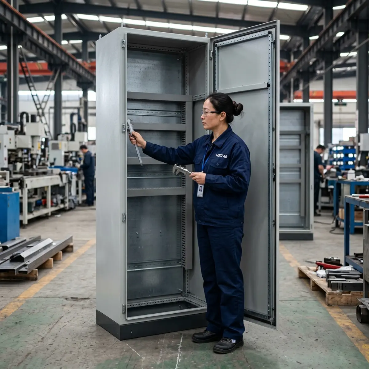
Freeze the Mechanical Interfaces That Stop Assembly
| Interface | Define in the RFQ | Typical first-article check |
|---|---|---|
| HMI and controls | Cutout, corner radius, bezel clearance, fasteners and support | Template or buyer-supplied component fit |
| Mounting plate | Datums, hole pattern, edge returns, standoffs and removal path | Pattern, flatness and enclosure fit |
| Cable entry | Gland plate, conduit cutouts, bend space and tool access | Cutout and fastener geometry |
| Thermal equipment | Fan, filter, vent or exchanger part number and keep-out zone | Opening, mounting and service clearance |
| Door system | Hinges, latches, gasket, bonding and installed door loads | Gap, operation, alignment and hardware fit |
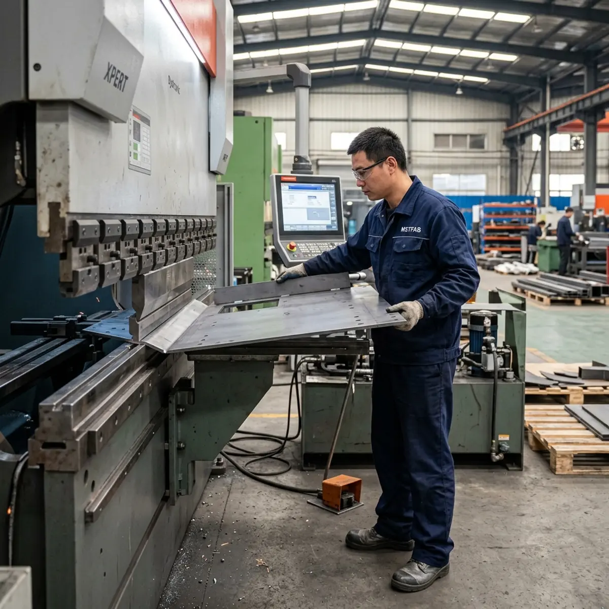
Do Not Let the 3D Model and 2D Drawing Disagree Quietly
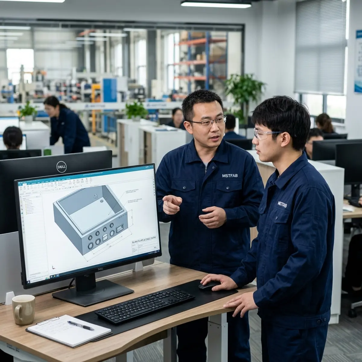
The model is useful for structure and interference review. The drawing should control tolerances, material, finish, hardware, critical characteristics and inspection notes. State which file governs when the two disagree and keep the same revision across quotation, first article and production.
For the broader design release, use the automation enclosure shell DFM checklist. This page focuses on what procurement should put into the RFQ and what evidence should return with the first article.
Manufacturing Review Before Release
Bend access
Check flange sequence, tool clearance and nearby holes before the flat pattern becomes a surprise.
Weld distortion
Define which seams are welded and which door, panel or mounting datums must remain controlled afterward.
Hardware access
Confirm insertion direction, grip range, tool access and replacement clearance for mechanical hardware.
Finish interfaces
Identify masking, grounding zones, threads, gasket lands, cosmetic faces and acceptable touch-up.
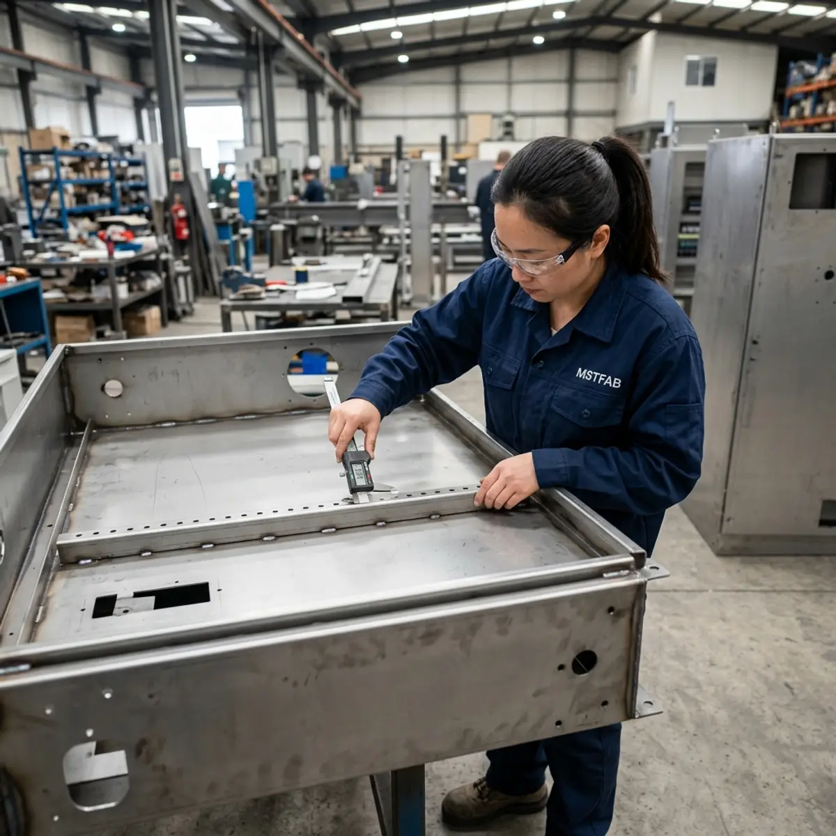
Buyer Trust Table
| Supplier statement | Evidence to request | Buyer value |
|---|---|---|
| “The HMI will fit” | Controlled cutout, corner radius and fit-check method | Protects the visible operator interface |
| “Cooling ready” | Buyer-selected component, cutout and service clearance | Separates shell fabrication from thermal-system design |
| “Grounding provided” | Stud locations, masking and buyer-approved bonding scheme | Keeps responsibility and geometry explicit |
| “Repeat production” | Approved FAI, critical checks and revision control | Connects later lots to the accepted baseline |
Automation Enclosure RFQ Checklist
- Current STEP and controlled 2D drawings
- Component interface and keep-out schedule
- HMI, button and indicator cutouts
- Mounting plate, rails and wire-duct datums
- Gland plates and cable bend space
- Fan, vent or heat-exchanger interfaces
- Door loads, hinges, latches and gasket
- Material, thickness, finish and masking
- FAI, fit checks and critical dimensions
- Quantity, packing and revision control
Frequently Asked Questions
Does MSTFAB supply PLCs, wiring or programming?
No. Standard scope is drawing-defined mechanical sheet metal. Electrical components, wiring, programming and system integration remain with the buyer or integrator.
Can mechanical hardware be installed?
Drawing-defined studs, inserts, hinges, latches and brackets can be included when identified in the approved quotation and BOM.
Who selects the cooling fan or heat exchanger?
The buyer or responsible thermal designer should select and size the equipment. The fabricator can reproduce its controlled mechanical interface.
Send the Interface Schedule With the Drawings
Share the mechanical files, buyer-installed component interfaces, material, finish, quantity and first-article requirements for a drawing review.
 WeChat Contact
 WhatsApp Me Directly