
How does direct-from-STEP sheet metal manufacturing accelerate production while eliminating drafting errors?
Direct manufacturing from 3D STEP files (AP203, AP214, or AP242) allows fabricators to import solid geometry directly into automated sheet metal CAM engines, bypassing manual 2D drafting. The software instantly verifies uniform sheet thickness, detects bend radii, calculates developed flat patterns using shop-calibrated K-factors, simulates multi-axis press brake tool collisions, and exports optimized nesting code directly to fiber lasers—reducing engineering lead time from days to hours while ensuring 100% geometric fidelity.
1. The STEP Standard: Transforming Digital CAD into Physical Sheet Metal
The Standard for the Exchange of Product Model Data (STEP / ISO 10303) is the universal lingua franca of modern mechanical engineering. Unlike proprietary CAD formats (SolidWorks .sldprt, Inventor .ipt, Creo .prt) that depend on software version compatibility, neutral STEP files (specifically AP214 and AP242 with embedded PMI) preserve exact boundary representation (B-Rep) solid geometry across all engineering platforms.
When quoting and manufacturing custom sheet metal enclosures, brackets, and chassis, starting from a clean 3D STEP model streamlines the entire front-end engineering workflow, slashing CAM programming time by over 70% and eliminating human drafting errors.
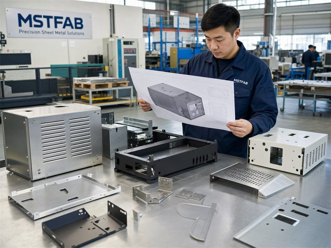
2. How CAM Software Unfolds 3D STEP Models
When a STEP file is loaded into MSTFAB’s automated sheet metal CAM system (such as TRUMPF TruTops Boost or Bystronic BySoft), the engine executes an intelligent 4-step parsing routine:
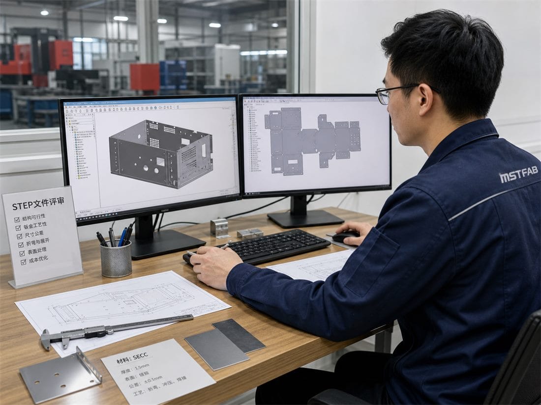
- Sheet Metal Feature Recognition: The algorithm identifies the base planar face, recognizes formed flanges, and calculates the true sheet thickness (t). If the model contains non-uniform wall thicknesses or zero-radius sharp bends, the software flags an error.
- Shop K-Factor & Bend Deduction: Every press brake tool set and material batch stretches slightly differently. The CAM engine replaces the designer’s generic CAD bend deduction with MSTFAB’s empirical, shop-calibrated K-factor table, ensuring the unfolded flat pattern produces the exact 3D dimensions after forming.
- Automatic Relief Generation: The software checks corner reliefs and flange transitions, confirming that tearing will not occur during press brake air bending.
- NC Nesting Generation: The unfolded 2D geometry is routed directly into dynamic laser nesting algorithms to maximize sheet utilization on standard 4×8 or 5×10 foot sheet stock.
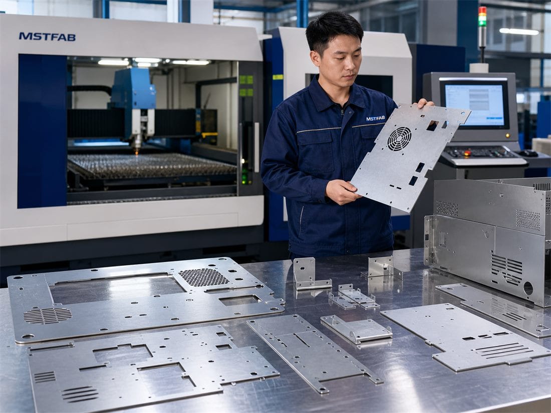
3. 3D Press Brake Simulation & Collision Avoidance
Once flat blanks are laser-cut and deburred, the 3D STEP data guides CNC press brake setup. The CAM software simulates the entire bending sequence in 3D, testing each bend against virtual models of our press brake punches, dies, backgauges, and machine frames.
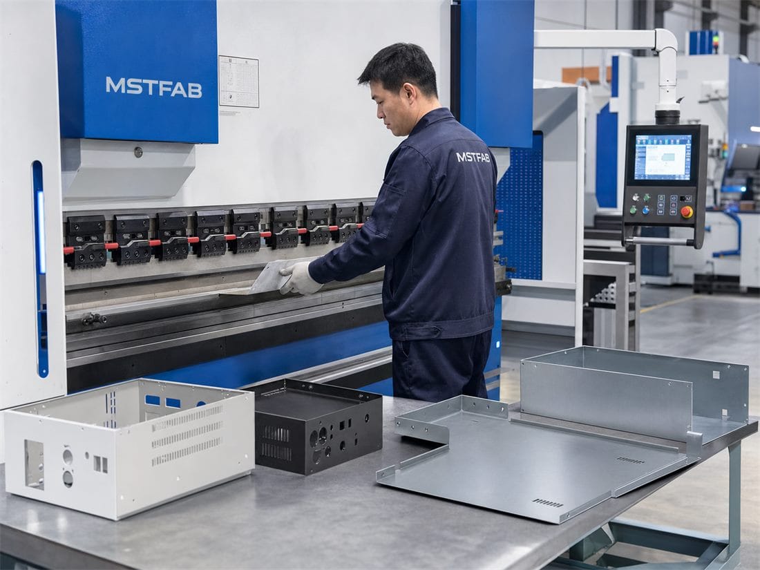
This virtual simulation identifies tooling collisions before a single piece of metal is bent, allowing programmers to select gooseneck punches, horn dies, or split tooling setups automatically.
4. Welding, PEM Hardware & Assembly Fit
The STEP model provides an indispensable assembly reference for hardware installation and welding cells:
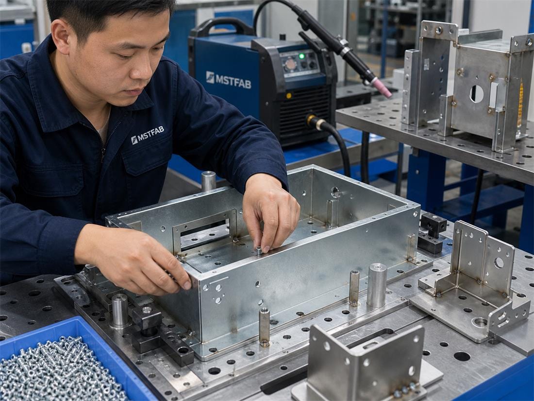
- Hardware Placement Verification: Clinch studs, standoffs, and nuts are installed on automated hydraulic presses, referencing coordinates derived directly from the 3D STEP model.
- Tab-and-Slot Welded Assemblies: Multi-part STEP assemblies are designed with laser-cut interlocking tabs that locate mating components with ±0.05 mm repeatability, enforcing mechanical squareness during welding without complex jigs.
5. Why You Should Always Pair STEP Files with 2D PDFs
While STEP models represent geometric shapes perfectly, they do not inherently convey manufacturing tolerances or finish specifications unless exported in the advanced STEP AP242 format with embedded Product and Manufacturing Information (PMI). In standard industrial practice, pairing your 3D STEP file with a 2D PDF drawing provides the ultimate zero-defect safety net:
- The 3D STEP model provides the geometry for laser nesting, K-factor unfolding, and CNC press brake simulation.
- The 2D PDF drawing defines critical-to-quality (CTQ) dimensional tolerances (e.g., ±0.1 mm on mounting holes), thread pitch, hardware part numbers, and surface finishes (e.g., RAL 7035 powder coat, ASTM A967 passivation).
6. STEP File Sheet Metal DFM & Tolerance Matrix
Ensure your 3D STEP models comply with standard sheet metal manufacturing rules:
| Design Parameter | Recommended Rule for STEP Models | Common 3D CAD Modeling Error | Impact on CAM Processing |
|---|---|---|---|
| Wall Thickness | 100% uniform sheet gauge throughout body | Extruding varied wall thicknesses on one part | CAM engine rejects part; cannot unfold |
| Inside Bend Radius | IR = 1.0t (Steel) / 1.5t (Alum) | Modeling zero-radius sharp inside corners | CAM must manually rebuild bend radii |
| Corner Bend Reliefs | Width ≥ 1.0t; Depth ≥ r + t | Missing reliefs; zero-gap slit notches | Sheet metal tears during press brake forming |
| Hole-to-Bend Spacing | Edge-to-tangent ≥ 2.5t + r | Holes placed directly in bend radius zone | Holes stretch into egg shape during bending |
| Minimum Flange Height | hmin ≥ 4.0t | Extremely short return lips (< 3.0 mm) | Flange slips into V-die opening; cannot form |
| Multi-Part Assemblies | Save each sheet metal component as individual STEP | Exporting entire 50-part assembly as one STEP | Requires manual disassembly and file separation |
Manufacture Custom Sheet Metal Directly from STEP Files
Upload your 3D STEP files (AP214/AP242) and PDF drawings. MSTFAB delivers instant DFM validation, automated K-factor unfolding, high-speed fiber laser cutting, and precision CNC bending.
 WeChat Contact
 WhatsApp Me Directly