
The Short Answer
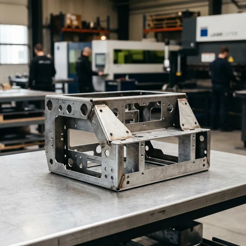
Yes, custom sheet metal parts can be quoted and unfolded directly from a 3D STEP (.step / .stp) file, provided you also specify material grade, surface finish, hardware callouts, and critical tolerances. While the STEP solid model defines exact 3D wall thickness, bend angles, and hole geometry for CAM programming, pairing it with a 2D PDF drawing or structured RFQ specification ensures threads, cosmetic faces, and inspection datums are never guessed.
Explore this guide
01 / 3D CAD vs. 2D Print Roles
Understand what a STEP model defines and what it leaves out.
Neutral 3D CAD formats (ISO 10303 AP203, AP214, and AP242 `.step` / `.stp` files) eliminate manual re-drawing errors by giving our CAM engineers exact boundary-representation solid geometry. Our software extracts wall thickness, calculates flat patterns using calibrated press-brake bend deductions, and checks multi-part assembly clearances in minutes.
However, a raw STEP file is purely geometric—unless PMI (Product and Manufacturing Information) is embedded, it does not carry thread pitches, PEM fastener part numbers, weld symbols, or powder-coat colors.
Captured in the 3D STEP file
Exact 3D solid geometry, sheet wall thickness, inside bend radii, hole diameters, flange lengths, and part-to-part assembly mating.
Missing without a 2D PDF or spec
Tapped hole thread callouts, self-clinching hardware specs, weld joint types, tight GD&T datums, grain direction, and RAL coating shade.
The ideal hybrid RFQ package
A 3D STEP file for automated flat-pattern unfolding paired with a 2D PDF drawing that calls out critical-to-quality (CTQ) dimensions and finishes.
Can we quote from STEP alone? Yes—if you do not have a 2D drawing ready for prototype quoting, simply state the material grade, finish, tapped hole sizes, and batch quantity in your RFQ notes.

02 / Engineering Review Workflow
How our engineers convert your STEP file into shop-ready tooling data.
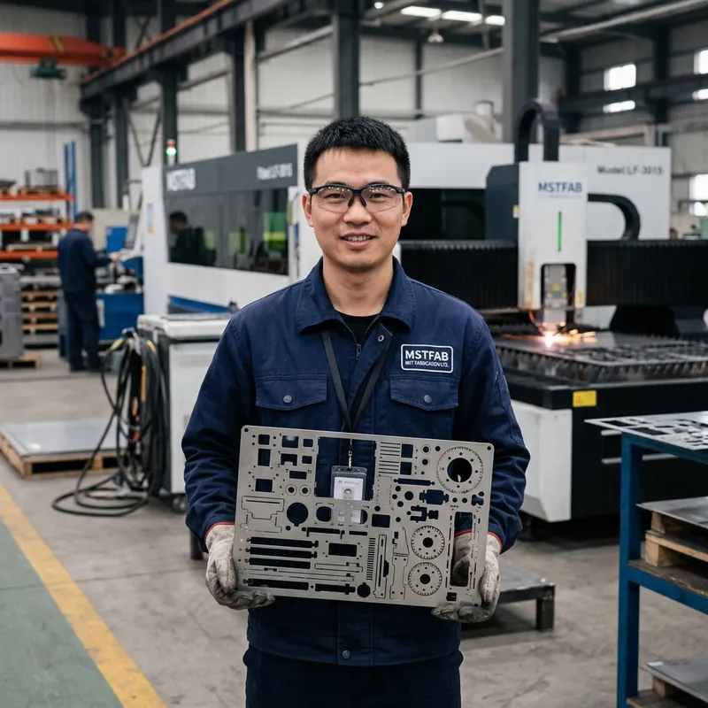
Before a single sheet is loaded onto the laser bed, every incoming STEP model passes through a four-stage engineering verification workflow to prevent unfolding errors and tool collisions.
- Solid body and uniform-thickness check: We verify that imported STEP bodies are watertight solids with uniform sheet thickness across all flat webs and formed flanges, flagging any accidentally tapered faces or non-uniform walls.
- Die-matched K-factor unfolding: Instead of trusting generic CAD default K-factors, we unfold your 3D part using empirical bend deduction tables matched to our actual punch radii and V-die openings.
- Press-brake collision simulation: Deep U-channels, return hems, and four-sided boxes are simulated in 3D bending software to confirm gooseneck punch clearance and bend sequence feasibility.
Once the flat pattern is locked, parts are laser-cut on CNC fiber lasers, formed via CNC bending, and assembled to your multi-body CAD structure.
03 / Resolving DFM Geometry Issues
Catch five common STEP modeling mistakes before cutting metal.
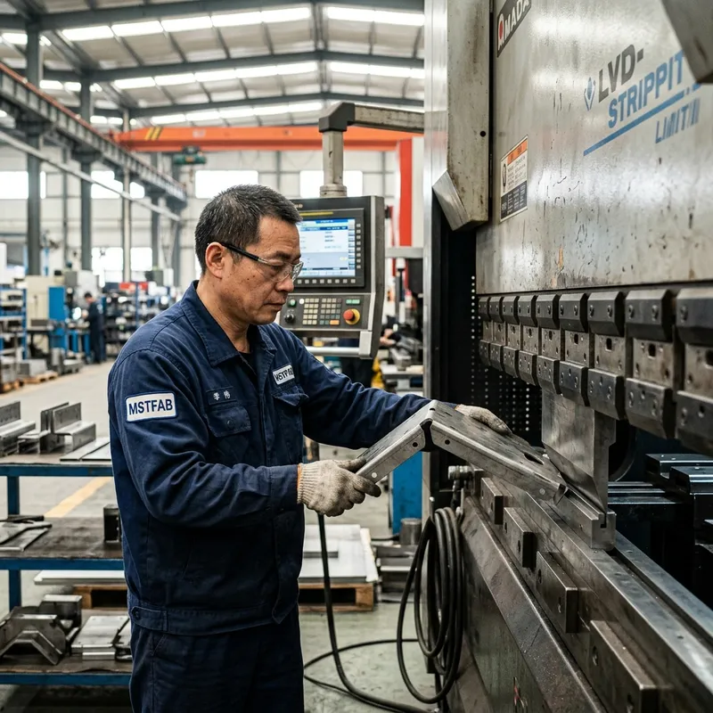
Parts modeled as solid blocks rather than native sheet-metal features frequently fail to unfold or tear during forming unless adjusted during DFM review.
- Zero-radius sharp internal corners that must be converted to a realistic inside bend radius (typically 1.0x sheet thickness for mild steel and stainless).
- Missing bend reliefs at flange intersections that cause corner tearing or raised metal pinch burrs during press-brake forming.
- Holes, slots, or PEM pilot bores placed closer than 2.0x–2.5x material thickness plus inside radius from the bend tangent line, leading to oval hole pulling.
- Flanges shorter than the minimum V-die bridge span (typically 4x–5x thickness), which cannot sit safely across standard lower dies.
- Modeled helical threads or countersinks that obscure nominal pilot hole diameters during automated 2D DXF extraction.
When our engineers spot any of these conditions in your STEP model, we return annotated 3D screenshots with practical adjustment options before production starts.
04 / Materials, Finishes and Tolerances
Pair your 3D CAD geometry with clear material and tolerance defaults.
To prevent over-tolerancing cost penalties or material substitutions, confirm the alloy family, surface protection, and general tolerance standard that applies to your STEP models.
- Carbon and pre-galvanized steels: SPCC cold-rolled steel, SPHC/Q235B hot-rolled pickled plate, and SGCC/DX51D galvanized steel for structural brackets, frames, and powder-coated cabinets.
- Austenitic stainless steels: 304, 304L, 316, and 316L stainless in 2B mill, No. 4 brushed, bead-blasted, or passivated condition for corrosion-resistant housings and hygienic guards.
- Aluminum alloys: 5052-H32 for tight cracking-free bending and 6061-T6 for flat plates or large-radius brackets, paired with chromate conversion or anodizing.
- General sheet metal tolerances: When no 2D tolerance block is supplied, linear cut features typically follow ISO 2768-m and formed bend dimensions follow ISO 2768-c or +/-0.25 mm to +/-0.5 mm depending on flange span.
If your part includes a Powder Coating build-up of 60–100 µm per side, indicate whether tight mating bores or sliding tracks in the STEP model represent pre-coat metal dimensions or post-coat finished dimensions.
05 / CAD-to-Production Matrix
Verify five manufacturing inputs alongside your STEP upload.
Use this checklist matrix to verify that your 3D STEP package contains everything required for a zero-delay quote and first-article build.
06 / Prototype and First-Article Inspection
Validate unfolded geometry with fast prototypes and documented FAI.
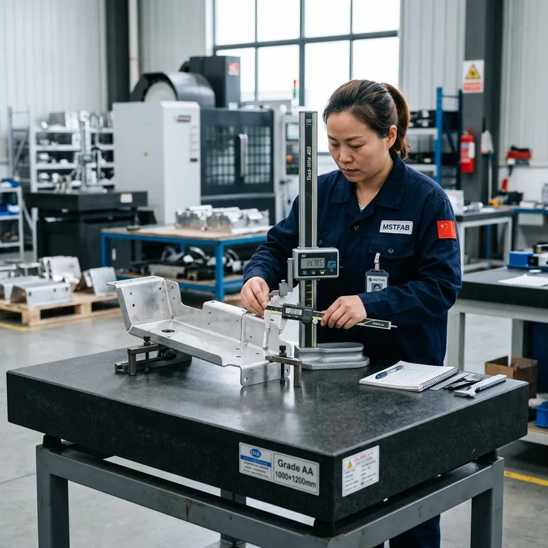
Because CNC fiber laser cutting and press brake bending require no hard stamping dies, moving from an approved STEP file to physical prototype parts takes days rather than weeks.
Under our ISO 9001 quality management system, first-off parts are checked with calibrated calipers, height gauges, pin gauges, and digital protractors—and for multi-part STEP assemblies, we perform a physical trial assembly on the shop floor to confirm hole alignment and door swing.
Once you approve the first-article inspection report (FAI), the validated flat-pattern DXF, press-brake program, and weld fixture setup are locked in our ERP system for repeatable batch production.
Explore our sheet metal quality control and FAI reporting process →
07 / Assembly Kitting and Scope
Receive subassemblies organized by your STEP bill of materials.
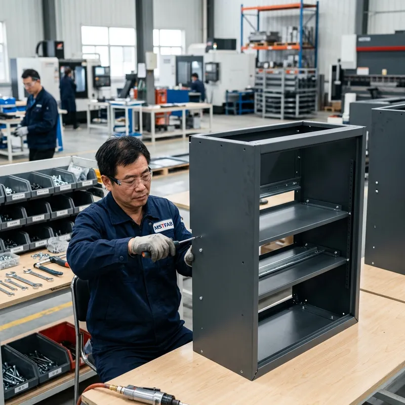
When you submit a multi-part STEP assembly—such as an electronics chassis with top cover, internal brackets, and hinge plates—we pack and label components by subassembly kit or ship pre-assembled housings protected in custom foam-lined export cartons.
Every shipment is accompanied by dimensional check sheets and material certificates traceable to your CAD part numbers.
Manufacturing scope: MSTFAB operates under an ISO 9001 quality management system and manufactures custom drawing-based sheet metal parts, welded frames, and empty enclosure shells from your CAD files. Final electrical wiring, active component integration, and end-product system certifications remain with the OEM.
08 / Ready-to-Review RFQ
Include eight items when submitting STEP files for quotation.
- 3D STEP file (.step / .stp)Export clean AP203, AP214, or AP242 solid bodies for each part or assembly.
- Companion 2D PDF drawingInclude a PDF print for threads, tight tolerances, and weld symbols when available.
- Material grade and thicknessState exact alloy (e.g., SPCC, 304 SS, 5052-H32) and verify gauge matches the 3D wall.
- Hardware and thread listSpecify M-series or UNC thread sizes, countersinks, and PEM fastener part numbers.
- Weld and corner seam instructionsIndicate whether meeting flange corners require TIG/MIG welding and flush dressing.
- Surface treatment and colorCall out powder coat RAL code, anodizing class, zinc plating, or brushed grain.
- Critical-to-fit datumsHighlight key mounting hole pitches or flatness zones that require FAI reporting.
- Prototype and batch quantitiesList initial prototype verification count alongside target production lot sizes.
Sending a complete STEP and specification package lets our engineers return DFM feedback and pricing without back-and-forth clarification delays.
Questions about sheet metal fabrication from STEP drawings
Is a 3D STEP file enough to quote and manufacture custom sheet metal parts?
Yes, for simple laser-cut and bent brackets without tapped holes or tight GD&T, a 3D STEP file plus written material, finish, and quantity notes is enough to quote and produce. If the part includes threads, PEM hardware, welded joints, or tight tolerances, include a 2D PDF drawing or annotated screenshot.
Why shouldn’t I just send a flat 2D DXF file instead of a 3D STEP model?
A 2D flat DXF exported from your CAD software uses whatever K-factor and bend radius were set on your computer, which may not match our press brake punches and V-dies—causing formed flange lengths to drift by 0.5 mm to 2.0 mm. Sending the 3D formed STEP model lets us calculate the exact flat pattern for our tooling.
What happens if the sheet thickness in my STEP model does not match standard mill gauges?
During DFM review, our engineers compare your modeled wall thickness against standard commercial sheet gauges (such as 1.0, 1.2, 1.5, 2.0, 2.5, or 3.0 mm) and confirm the exact material thickness and inside bend adjustment with you before unfolding.
Can I upload a single multi-body STEP file containing a complete enclosure assembly?
Yes. We routinely process multi-body assembly STEP files, separate each sheet metal component into a structured bill of materials, verify inter-part hole alignment, and quote either individual parts or the welded/fastened assembly.
Should I model helical threads inside tapped holes in the STEP file?
No. Model tapped holes at their nominal tap-drill pilot diameter (for example, Ø4.2 mm for an M5 x 0.8 thread) and identify the thread callout on a 2D PDF drawing or table. Modeled 3D helical threads splinter circular edges and interfere with automated laser CAM recognition.
What quality documents are provided for parts built from STEP files?
Under our ISO 9001 quality system, we provide raw material mill test certificates (MTCs), first-article dimensional inspection reports (FAI) checked against your 3D/2D specs, and finishing verification records upon request.
Technical references
These international standards govern 3D CAD product data exchange and general sheet metal dimensional tolerances.
- ISO 10303-242 (STEP AP242) — Managed model-based 3D engineering data exchange
- ISO 2768-1 & ISO 2768-2 — General tolerances for linear, angular, and geometrical dimensions without individual tolerance indications
- ISO 9013 — Thermal cutting classification of thermal cuts, geometrical product specification and quality tolerances
Upload your 3D STEP and 2D PDF files for an engineering review.
Share your CAD files, material grade, finish callouts, and target batch quantity. MSTFAB will check unfolding feasibility and return a clear quotation.
Have a question first? caroline@mstfab.com
 WeChat Contact
 WhatsApp Me Directly