
How does an integrated cutting, bending, and welding sequence ensure precision in complex sheet metal fabrication?
An integrated workflow coordinates manufacturing steps into a synchronized chain: (1) high-precision fiber laser cutting of flat blanks held to ±0.05 mm with calibrated K-factor bend deductions, (2) multi-axis CNC press brake forming utilizing sequenced gooseneck and segmented tooling to prevent ram collisions while controlling bend angles within ±0.25°, (3) strategic self-clinching PEM hardware insertion (performed pre-bending on flat blanks whenever possible for maximum press access), and (4) rigid 3D fixture welding (TIG/MIG) employing symmetrical skip sequences to balance thermal shrinkage, guaranteeing final assembly envelope and mounting pad coplanarity within ±0.5 mm.
1. The Triad of Sheet Metal Manufacturing
Precision sheet metal fabrication is rarely a single-process operation. Over 85% of industrial enclosures, equipment chassis, and structural brackets pass through three core mechanical manufacturing stages: cutting, bending, and welding. Each step is inextricably linked to the others; an error in flat blank development will distort a formed flange, and an uncompensated bend angle will cause massive joint gaps that make sound welding impossible.
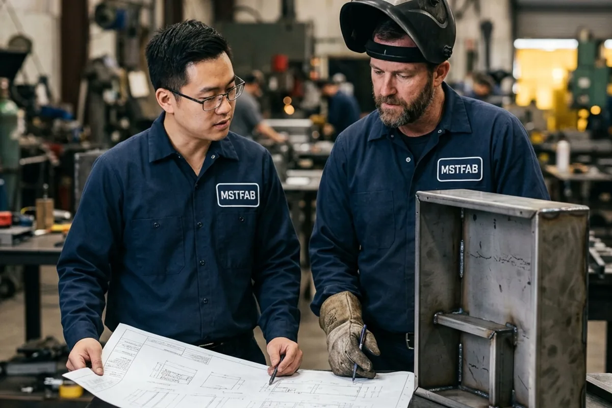
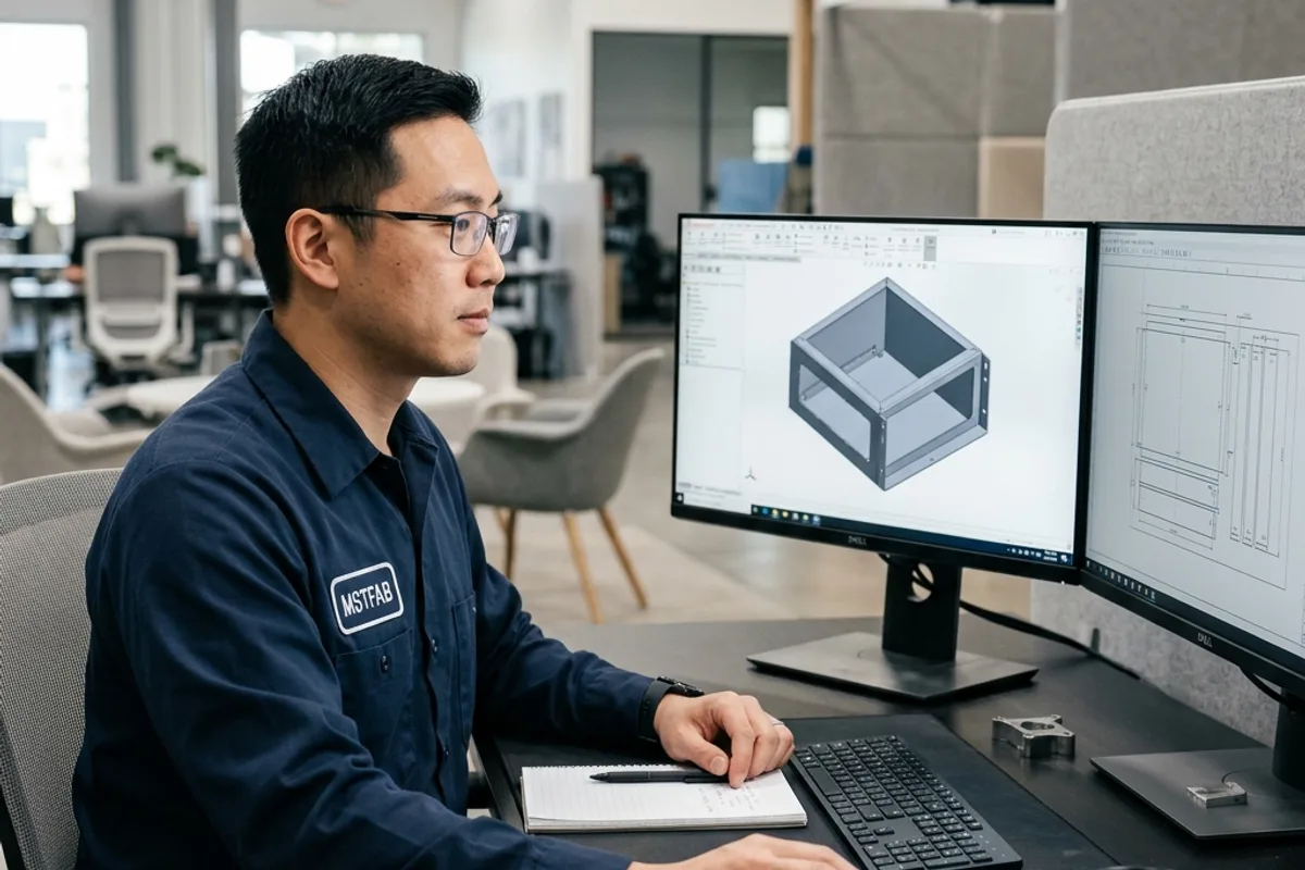
When cutting, bending, and welding are handled by fragmented subcontractors, tolerance stack-up and finger-pointing are inevitable. MSTFAB unifies these three disciplines under a single synchronized engineering workflow, utilizing digital thread traceability from 3D CAD modeling through final dimensional inspection.
2. Stage 1: High-Speed Fiber Laser Cutting & Blank Optimization
The manufacturing process begins on high-power fiber laser cutting centers (6 kW to 15 kW). Unlike mechanical shearing or turret punching, laser cutting introduces no mechanical blank shear stress, leaving the metal flat and pristine.
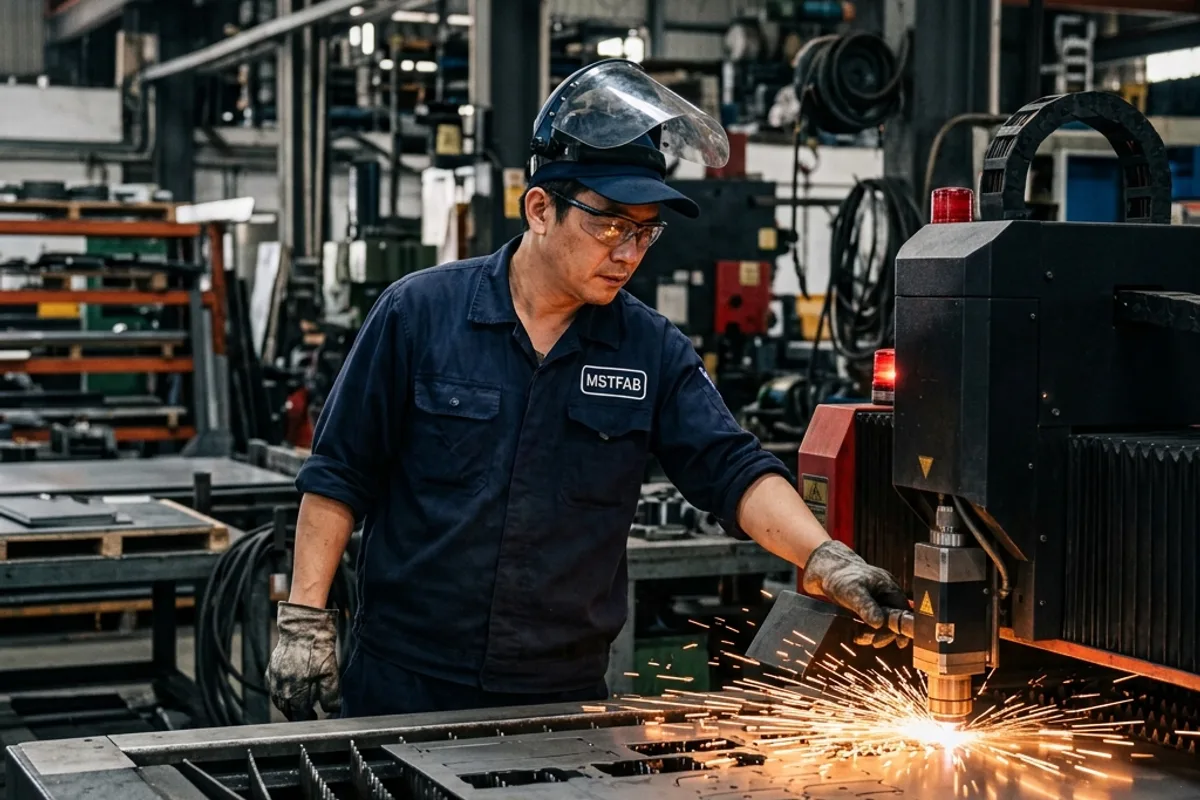
To ensure perfect mating during downstream welding, flat blanks are cut with interlocking tab-and-slot locating features. Mortise slots and tenon tabs are held to ±0.05 mm positional tolerance, allowing complex three-dimensional enclosures to snap together self-squaring before a single weld tack is struck.
3. Stage 2: Precision CNC Press Brake Forming
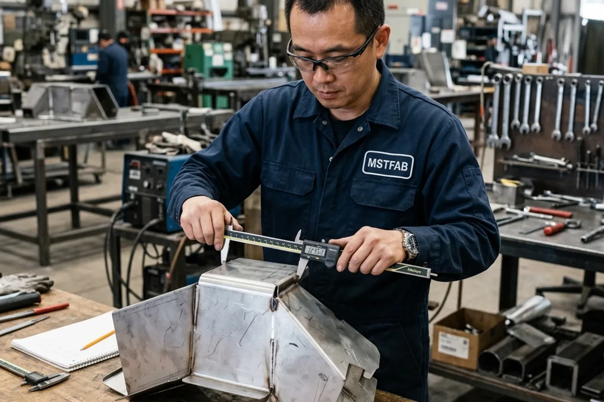
Following laser blanking and edge deburring, parts transfer to multi-axis CNC press brakes. Press brake forming transforms 2D blanks into rigid 3D geometries through controlled air bending.
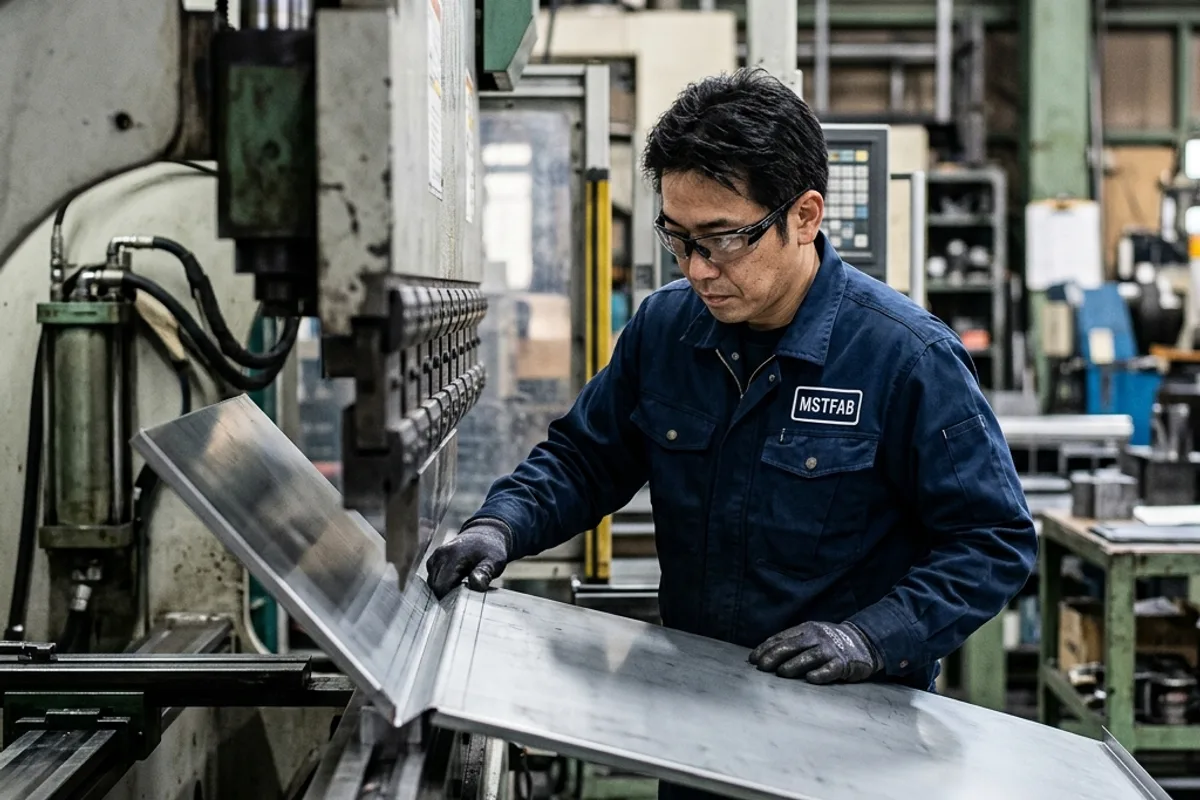
The sequence of bends must be rigorously simulated in 3D CAM software before touching the machine. Complex U-channels, deep chassis boxes, and return flanges can collide with the machine ram, backgauges, or punch holders. MSTFAB utilizes segmented tooling, tall gooseneck punches, and horn dies to provide collision clearance for deep-box return lips.
4. Stage 3: Certified Welding & Thermal Fixturing
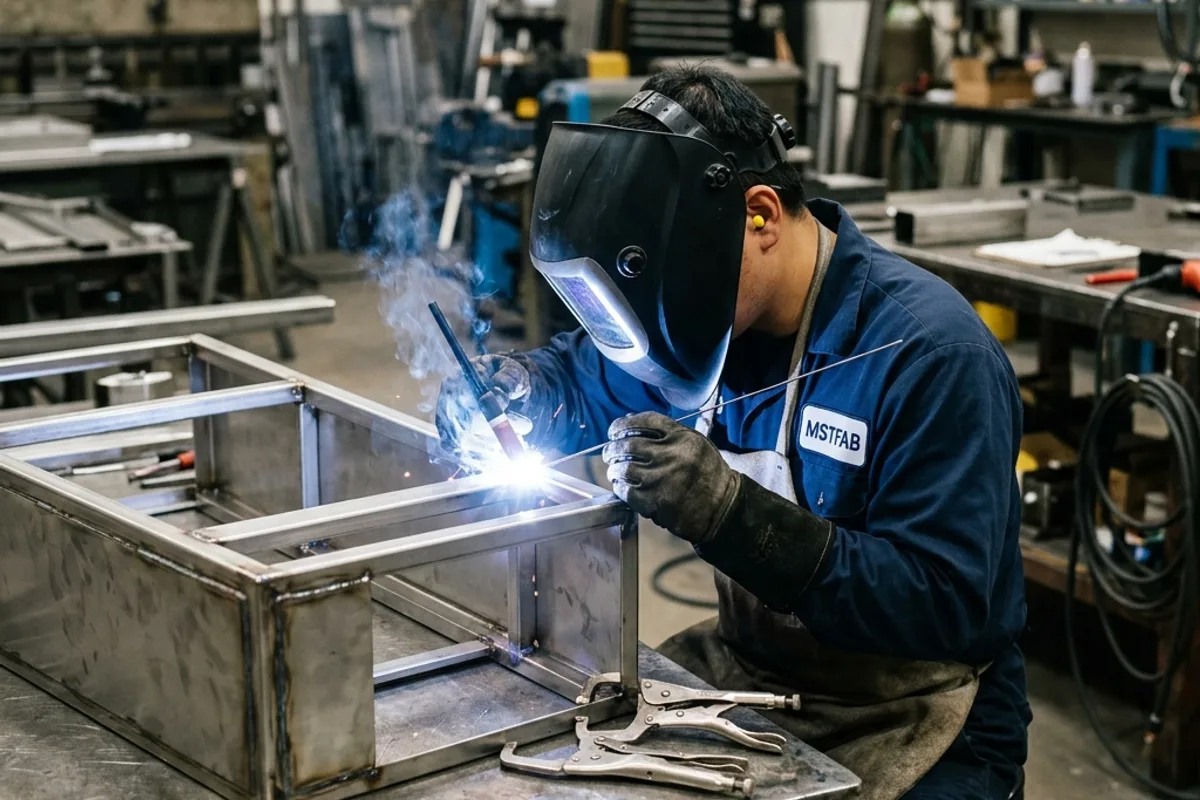
Welding joins formed sheet metal components into monolithic, high-strength structural enclosures and machine frames. Depending on the material and functional requirements, certified welders deploy pulsed TIG or synergic MIG welding:
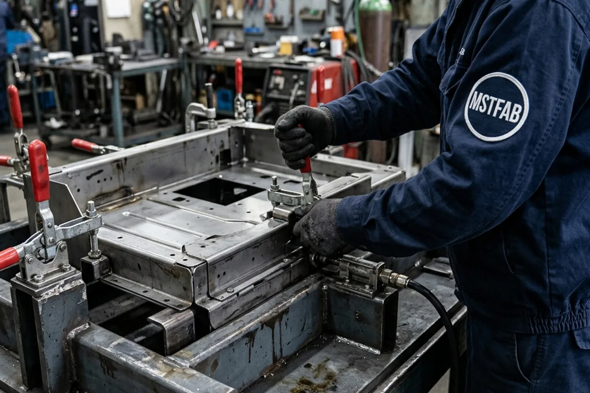
To eliminate welding warpage, assemblies are clamped into rigid modular fixture tables. Heavy copper chill blocks back up each weld seam, drawing away intense heat through conduction to prevent panel oil-canning.
5. Weld Dressing, Hardware & Turnkey Assembly
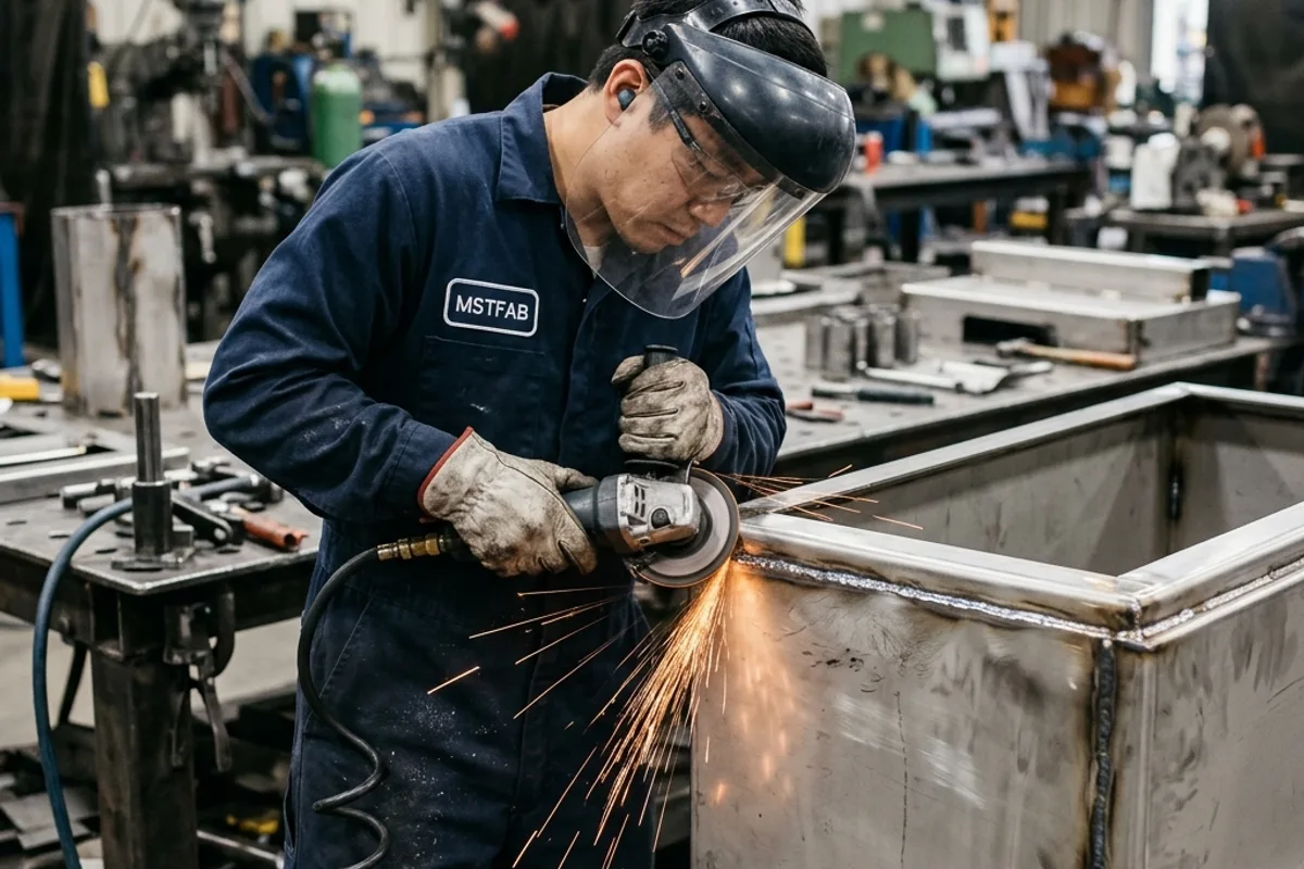
After welding, outside corner welds are ground dead-flush using pneumatic abrasive sanders, restoring a crisp, seamless corner radius that matches adjacent sheet metal contours.
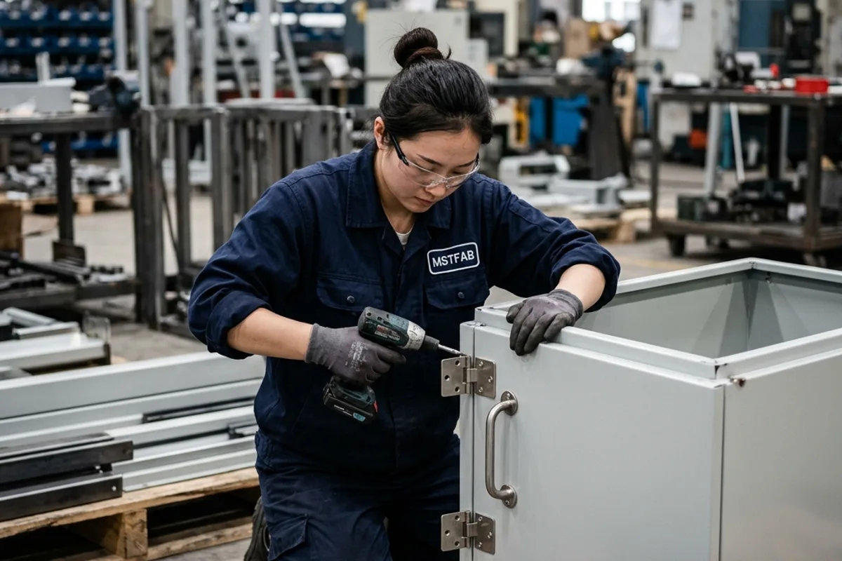
Secondary operations integrate self-clinching fasteners, hinges, and mounting hardware, followed by comprehensive mechanical trial fitting before powder coating or plating.
6. Integrated Workflow Quality & Tolerance Matrix
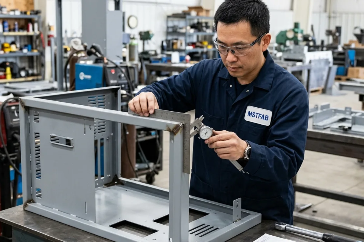
Synchronizing cutting, bending, and welding requires managing cumulative tolerance stack-up across every transition:
| Workflow Phase | Key Manufacturing Operation | Process Tolerance Capability | Downstream Impact |
|---|---|---|---|
| Phase 1: Cutting | Fiber laser cutting & deburring | ±0.05 mm hole pitch; ±0.10 mm profile | Guarantees flat blank perimeter & tab-slot fit |
| Phase 2: Hardware (Pre-Bend) | Hydraulic PEM fastener insertion | ±0.10 mm true position; 100% force monitor | Ensures full press tooling clearance on flat sheet |
| Phase 3: Bending | CNC multi-axis press brake forming | ±0.25 mm flange height; ±0.3° bend angle | Determines 3D assembly enclosure fit & corner gaps |
| Phase 4: Welding | Pulsed TIG / MIG with fixture restraint | Δ ≤ 0.5 mm squareness; 100% fusion | Provides structural rigidity & environmental seal |
| Phase 5: Dressing | Pneumatic corner weld leveling | Flush ±0.05 mm; sheet thinning ≤ 5% | Delivers seamless Class A cosmetic transition |
| Phase 6: Finishing | Electrostatic powder coating / anodizing | 75–100 μm DFT; Class 5B cross-hatch | Guarantees 1000+ hrs salt spray corrosion resistance |
Simplify Your Supply Chain with Turnkey Sheet Metal Fabrication
MSTFAB unifies laser cutting, CNC press brake forming, certified welding, hardware insertion, and powder coating under one roof. Eliminate multi-vendor finger-pointing and get precision assemblies on schedule.
 WeChat Contact
 WhatsApp Me Directly