
How do precision DFM principles and GD&T controls guarantee flawless assembly fit in custom sheet metal chassis fabrication?
Flawless sheet metal chassis fabrication requires establishing a clear functional datum reference frame (assigning primary mounting base as Datum A, rear I/O face as Datum B, and card-guide rail as Datum C), performing 3D worst-case and RSS tolerance stack-up analysis to counteract multi-bend angular dispersion (±0.5° per bend), maintaining cutout-to-bend clearance ≥ 2.5t + r to prevent hole distortion, installing self-clinching PEM standoffs with automated insertion monitoring, and verifying 19-inch rackmount rails, card-guide slots, and diagonal squareness within ±0.25 mm via coordinate measuring machine (CMM) probing.
1. The Engineering Challenge: High-Density Packaging in Custom Chassis
Modern electronic, telecommunication, and medical chassis (such as 19-inch EIA-310 rackmount enclosures from 1U to 8U, modular instrumentation sub-racks, and desktop computer housings) pack hundreds of tightly toleranced electronic components into compact metal envelopes. A single chassis must precisely align printed circuit boards (PCBs), multi-pin backplanes, card-edge connectors, slide-in power supplies, hot-swappable drive trays, and front-panel display interfaces.
Unlike machined billet enclosures, sheet metal chassis are composed of laser-cut, stamped, and formed sheet components joined by spot welds, mechanical rivets, or clinch fasteners. Each forming operation introduces elastic springback and geometric variance. Without rigorous Design for Manufacturability (DFM) and statistical tolerance management, cumulative dimensional stack-up will cause backplane connectors to stub, daughter cards to jam in their guides, and chassis slide rails to bind inside standard server racks.
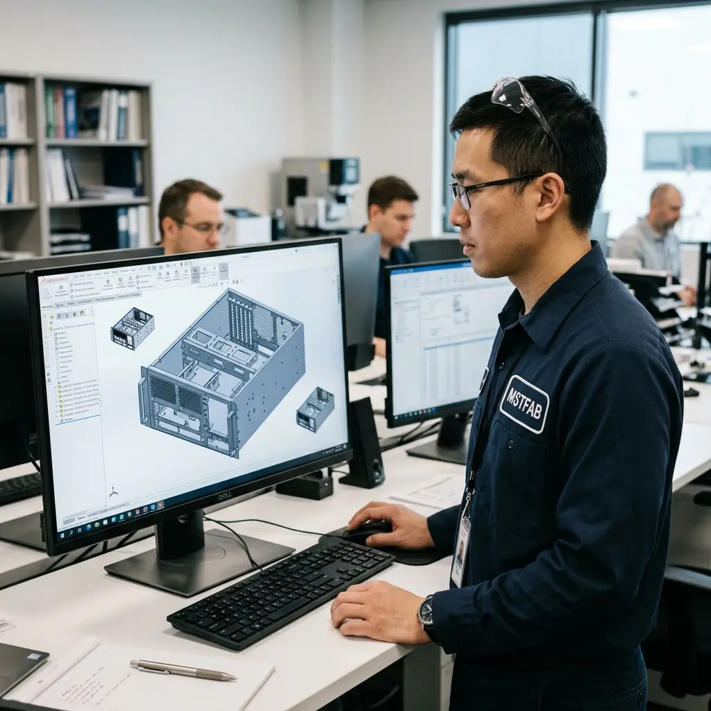
2. GD&T Datum Schemes & Dimensional Hierarchy
The foundation of chassis precision is establishing a robust Geometric Dimensioning and Tolerancing (GD&T) datum reference frame per ASME Y14.5-2018. Ambiguous drawings that dimension all features from arbitrary edges guarantee assembly failure:
- Primary Datum [A] (The Mounting Floor / Motherboard Tray): Defines the fundamental mounting plane. Flatness must be tightly controlled (≤ 0.3 mm across the floor) to prevent PCB mechanical twisting and solder joint micro-cracking when standoffs are secured.
- Secondary Datum [B] (The Rear Connector Faceplate): Formed perpendicular to Datum A. Controls the true position of critical I/O cutouts (D-Sub, USB, RJ45, optical transceivers) relative to motherboard mounting holes.
- Tertiary Datum [C] (The Primary Card-Guide Rail / Side Flange): Controls lateral positioning and rail-to-rail parallelism, ensuring slide-in modules dock cleanly into backplane receptacles without axial misalignment.

3. Tolerance Stack-Up Analysis: Linear vs. Formed Dimensions
Engineers must understand the critical difference between two-dimensional flat cutting accuracy and three-dimensional formed tolerance dispersion:
When cutting flat blanks on a CNC fiber laser, hole-to-hole center distances on the same plane are maintained within an astonishing ±0.05 mm. However, the moment a sheet metal blank passes through a CNC press brake, bend angle variance (±0.3° to ±0.5°), material thickness tolerances (±0.05 mm), and tooling radius clearances compound. Across a U-channel chassis with four consecutive bends, tolerance stack-up can easily reach ±0.6 mm to ±1.0 mm if dimensioned sequentially.
To eliminate this error loop, MSTFAB applies three DFM design rules:
- Direct Dimensioning from Functional Datums: Never chain-dimension formed flanges. All mounting hole locations must be dimensioned directly from the primary functional datum surface.
- Root-Sum-Square (RSS) Statistical Tolerancing: Rather than using unrealistic worst-case arithmetic tolerances that drive manufacturing costs unnecessarily high, design around RSS statistical tolerancing (σtotal = √(∑σi2)), sizing internal guide clearances to accommodate 3σ process capability.
- Slotted Mounting Holes on Secondary Brackets: Where internal partitions or drive cages bridge between opposing formed sidewalls, design one side with precision round holes and the opposing side with slotted clearance holes (±1.0 mm travel) to absorb cross-chassis bend variations without inducing stress on chassis corners.
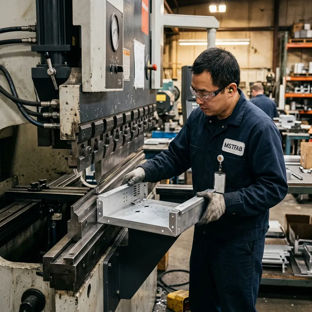
4. Cutout DFM & Distance to Bend Lines
When a metal sheet is bent over a press brake die, the metal in the plastic deformation zone flows: the inner radius compresses while the outer radius undergoes severe tensile stretching. If connector cutouts, ventilation louvers, or fastener holes are placed too close to the bend line, the plastic deformation will draw the hole into an out-of-round egg shape, bowing the panel edge and preventing I/O connectors from snapping flush.
- Minimum Hole-to-Bend Distance: The edge of any cutout or hole must maintain a minimum distance from the bend tangent line equal to 2.5× material thickness plus the inside bend radius (d ≥ 2.5t + r).
- Relief Notching: If a connector cutout must extend close to a bend line due to packaging constraints, the designer must incorporate rectangular or teardrop bend relief slots extending past the bend tangent to isolate forming stresses from the cutout perimeter.
- Minimum Flange Height: Return stiffener flanges must meet the minimum press brake die bridge requirement: hmin ≥ 4.0t. Flanges designed shorter than this threshold cannot bridge the V-die opening and will slip into the die trough, resulting in severe angle inaccuracy and edge gouging.
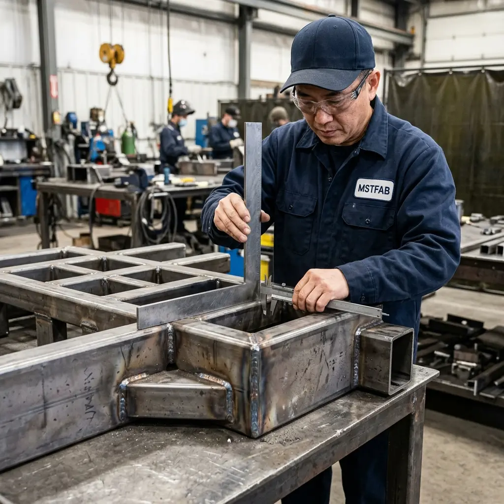
5. Precision Welding & Flush Weld Blending
Chassis corners and structural partition joints often require welding to provide structural shear rigidity and EMI/RFI shielding. However, weld beads must not interfere with sliding cards, mating top covers, or rack slide rails.
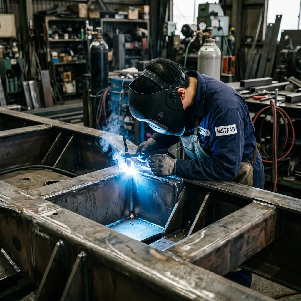
Corner seams are joined using pulsed TIG or fiber laser welding. All exterior corner weld crowns are ground dead-flush using pneumatic abrasive sanders, ensuring that external slide rails mount flat against the chassis sidewalls without any high-spot rocking.

6. Hardware Clinching & Mechanical Trial Fitting
A typical 19-inch chassis contains dozens of self-clinching fasteners: blind threaded standoffs for motherboard isolation, flush-head studs for grounding lugs, and miniature nuts for card guides. To prevent loose or canted fasteners, MSTFAB utilizes CNC hydraulic insertion presses with automated force-displacement process monitoring.
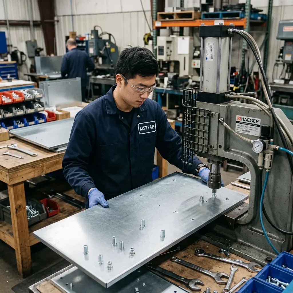
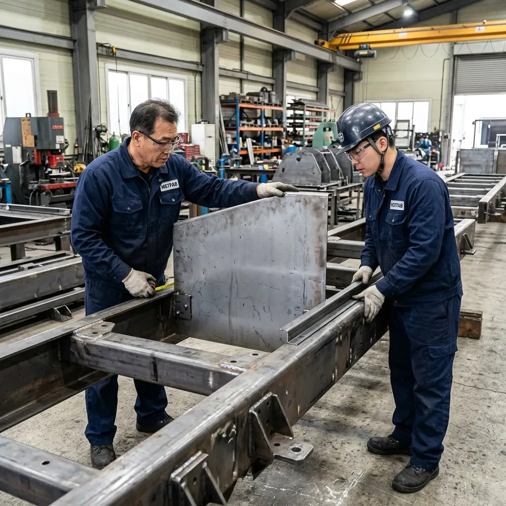
Before batch finishing, bare metal first-article prototypes undergo complete mechanical trial fitting: golden sample motherboards, card guides, power supply modules, and cover plates are installed to verify zero interference across all internal compartments.
7. CMM Inspection & Tolerance Matrix
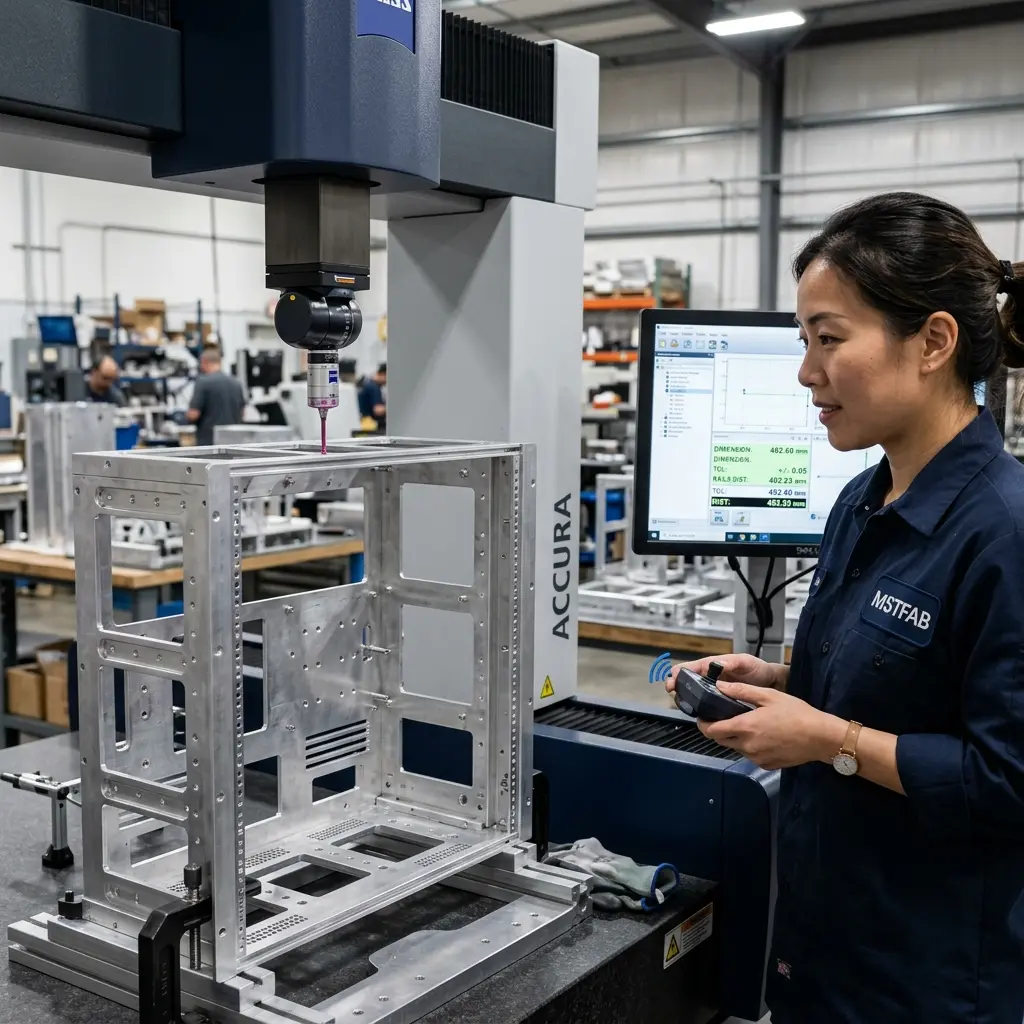
Critical card-guide pitches, motherboard standoff true positions, and EIA-310 rack flange hole spacings are 100% verified using 3D Coordinate Measuring Machines (CMM) and calibrated optical vision systems:
| Chassis Feature | Reference Standard | MSTFAB Standard Tolerance | Assembly Impact |
|---|---|---|---|
| Rackmount Flange Width | EIA-310-D / IEC 60297 | 482.6 +0.0 / -0.8 mm (19.00 in) | Mounting fit inside standard server cabinets |
| Chassis Height (per U) | EIA-310-D (44.45 mm / 1.75 in per U) | Nominal -0.8 mm clearance allowance | Zero vertical interference with adjacent rack units |
| PCB Standoff True Position | ASME Y14.5 Position Boundary | Ø 0.20 mm MMC to Datum A, B, C | Motherboard mounting screws start without cross-threading |
| Card-Guide Parallelism | Opposing guide rails | ≤ 0.25 mm total indicator reading (TIR) | Prevents plug-in PCB binding or connector misalignment |
| Motherboard Tray Flatness | Planar envelope | ≤ 0.30 mm across 400×400 mm area | Prevents PCB solder-ball stress and circuit micro-fracture |
| Diagonal Squareness | Corner-to-corner delta | Δ ≤ 0.50 mm across chassis corners | Guarantees top cover drops into place cleanly |
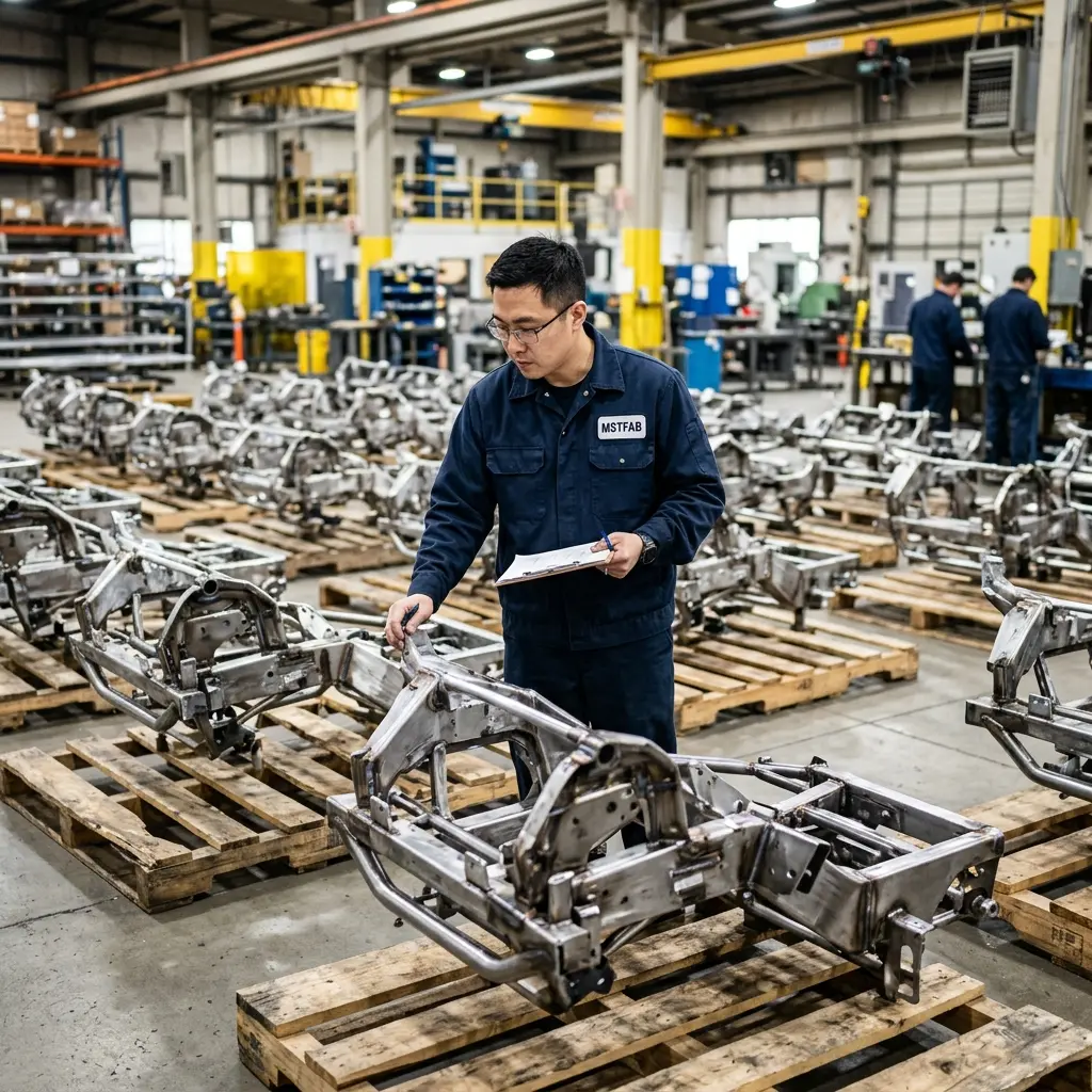
Eliminate Assembly Binding in Your Sheet Metal Chassis
MSTFAB provides complete chassis DFM analysis, precision fiber laser cutting, multi-axis CNC forming, automated PEM hardware insertion, and 100% CMM verification for rackmount, desktop, and industrial electronics.
 WeChat Contact
 WhatsApp Me Directly