
⚡ Direct Answer: How Are Custom Test Equipment Enclosures Engineered & Fabricated?
Custom test equipment enclosures are precision-engineered sheet metal housings designed to shield, mount, and cool sensitive measurement electronics, automated test equipment (ATE), RF analyzers, and laboratory diagnostic instruments. Unlike generic off-the-shelf plastic or extruded aluminum project boxes, custom test enclosures are fabricated to exact PCB mounting hole datums (±0.1 mm), incorporate dense laser-cut I/O connector arrays (BNC, SMA, D-sub, USB), feature continuous 360° EMC/EMI Faraday cage shielding, and include selective conductive masking for zero-resistance chassis grounding. MSTFAB manufactures build-to-print bare metal test equipment enclosures in aluminum 5052, stainless steel 304, and cold-rolled steel from 5-piece prototype runs to serial production batches.
Every electronics design engineer knows the frustration: you spend six months perfecting a multi-channel signal acquisition board with sub-microvolt noise floors, only to cram it into an off-the-shelf plastic box or hand-drilled aluminum extrusion. The connectors bind during assembly, thermal hot-spots throttle the CPU, and stray 2.4 GHz WiFi signals corrupt your high-precision measurements.
In industrial metrology, aerospace avionics validation, medical device QA, and semiconductor automated testing, custom test equipment enclosures are not merely packaging—they are an active mechanical component of your measurement system. Below is our shop-floor DFM guide on how to design and source custom test equipment enclosures that protect your electronics, accelerate assembly, and meet stringent CE, FCC, and MIL-STD compliance.
1. The Problem with Generic Boxes: Why Custom Test Equipment Enclosures Win
Hardware startups and test engineers frequently begin with off-the-shelf catalog enclosures to save initial tooling costs. However, once you move from breadboard proof-of-concept to field validation or customer shipments, catalog enclosures quickly turn into a manufacturing bottleneck:
- The Milling Surcharge Trap: Modifying a standard die-cast or extruded box requires post-machining 30+ connector cutouts, display bezels, and ventilation slots. Milling hardened die-cast walls is slow, expensive, and leaves raw, un-anodized edges vulnerable to corrosion.
- Fixed PCB Stand-off Locations: Catalog boxes force you to compromise your optimal PCB trace routing to match pre-molded mounting bosses.
- Inadequate Thermal Management: Off-the-shelf boxes rarely offer optimized front-to-back or bottom-to-top convection paths, causing heat buildup around sensitive ADCs and power amplifiers.
- Compromised RF & EMC Shielding: Plastic cases require messy conductive spray coatings that peel over time, while split-body catalog extrusions create non-conductive gaps along anodized joints.
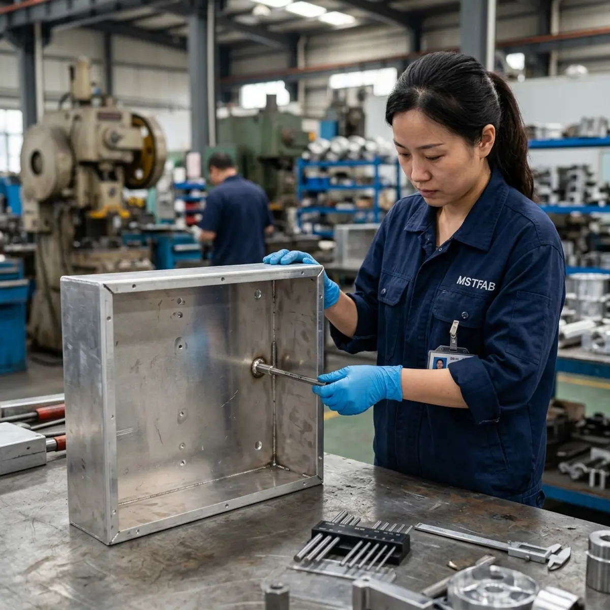
2. Sub-Millimeter Precision: Internal PCB Mounting & Standoff Architecture
In precision test instruments, mounting tolerances are critical. A standoff positioned 0.4 mm out of place will flex a multilayer FR4 PCB during screw torque-down, micro-cracking solder joints under fine-pitch BGA chips.
At MSTFAB, we employ three complementary techniques for internal mounting hardware in custom test equipment enclosures:
- Capacitive Discharge (CD) Stud Welding: For clean cosmetic exteriors where zero tooling marks are permitted on the front or top fascia, we weld stainless steel or aluminum threaded studs to the interior chassis surface. The short-duration weld pulse leaves the outer cosmetic face completely pristine.
- Pneumatic PEM Self-Clinching Standoffs: For heavy multi-board assemblies, we press genuine PennEngineering (PEM) blind or through-hole standoffs (e.g., PEM SOSG, SO, or BSOS) into laser-pierced holes under controlled tonnage. This guarantees pull-out and torque-out resistance exceeding 12 Nm.
- Toleranced Datum Locators: Laser cutting delivers hole pitch repeatability within ±0.05 mm, ensuring that your motherboard, daughtercards, and power distribution modules drop into the chassis without filing or reaming on your assembly line.
Always designate one PCB mounting hole as your primary alignment datum with a close-tolerance round hole, and specify adjacent mounting holes as slots (±0.3 mm expansion room). This isolates your sensitive measurement circuitry from mechanical stresses caused by ambient thermal expansion differences between aluminum chassis ($23 imes 10^{-6}/ ext{K}$) and FR4 circuit boards ($14 imes 10^{-6}/ ext{K}$).
3. High-Density I/O Panels: Laser Cutouts for BNC, SMA, and Multi-Pin Connectors
Automated test equipment (ATE) and benchtop instruments demand dense clusters of RF jacks, fiber-optic pass-throughs, USB-C ports, and high-current terminal blocks.
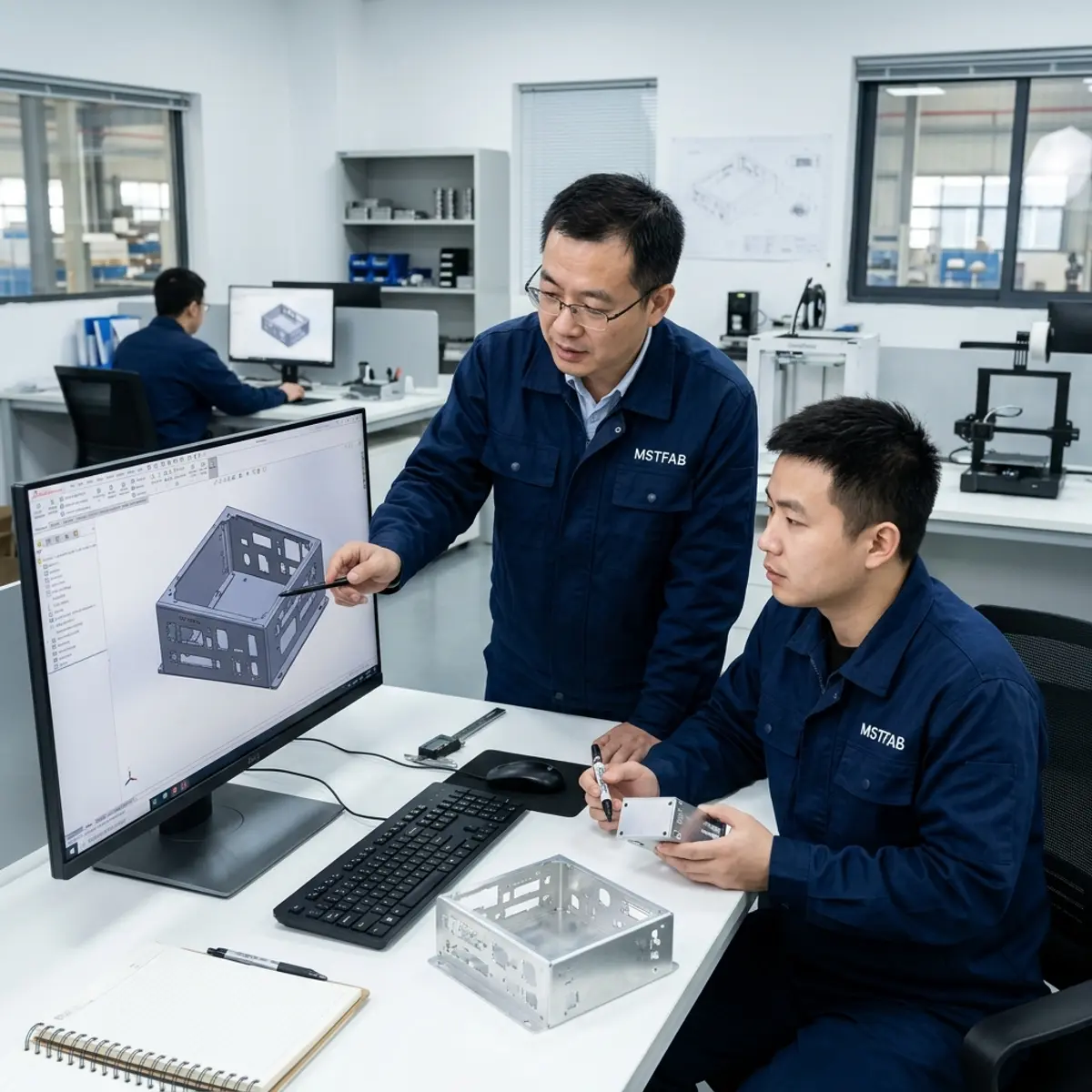
When engineering high-density I/O panels for custom test equipment enclosures, we enforce three fundamental DFM rules:
- Hole-to-Bend Relief Clearances: BNC and SMA D-flat holes must maintain a minimum distance of $2.5 imes ext{sheet thickness} + ext{bend radius}$ from any formed flange. Placing holes closer to a bend causes oval distortion during CNC press brake forming, preventing connector mounting nuts from seating flat.
- D-Flat Anti-Rotation Geometry: For coaxial RF bulkheads, we laser-cut precise “D-shaped” or double-D keyed profiles rather than standard round holes, preventing connectors from rotating and twisting internal coax wiring when technicians tighten external cables.
- Removable Modular I/O Plates: If your product line has multiple hardware variants (e.g., 4-channel vs. 8-channel vs. optical options), design the main chassis with a standardized rectangular rear opening, and let MSTFAB fabricate interchangeable modular sub-panels. This saves thousands of dollars in overall inventory costs.
4. EMC / EMI Shielding & RF Attenuation Architecture
A test instrument that leaks electromagnetic radiation—or admits interference from nearby motor drives and radio towers—cannot produce dependable calibration data.
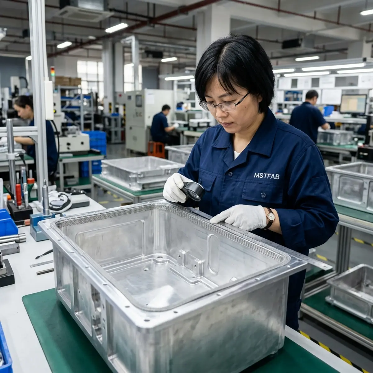
To achieve 60 dB to 90 dB of electromagnetic shielding attenuation across 10 MHz to 10 GHz frequencies, MSTFAB implements four shielding design standards:
- Overlapping Labyrinth Seams: Rather than simple butt joints, top covers and side chassis are formed with interlocking return flanges that form a continuous tortuous path, preventing RF wave leakage along enclosure edges.
- Conductive Gasket Compression Channels: Flanges can be formed with dedicated recess channels to seat nickel-graphite conductive silicone O-rings, wire mesh gaskets, or beryllium copper fingerstock.
- Fastener Pitch vs. Target Frequency: Shielding integrity depends on the distance between cover screws. To prevent high-frequency leakage, fastener spacing must satisfy $d < lambda / 20$. For a 1 GHz instrument ($lambda = 300 ext{ mm}$), screw spacing must not exceed 15 mm along unshielded seams.
- Selective Conductive Finishing & Masking: Powder coating is an electrical insulator. We apply custom high-temperature silicone masking tapes to internal flange mating surfaces, ground studs, and connector perimeters prior to powder coating. Internal surfaces are finished in clear chemical conversion coat (Chromate / Alodine per MIL-DTL-5541 Type II Class 3), maintaining low surface contact resistance (< 0.05 ohms) for continuous grounding.
5. Test Equipment Enclosure Decision Matrix: Off-The-Shelf vs. Custom Sheet Metal
Before committing engineering resources, review this technical trade-off matrix comparing standard procurement paths for instrument and test fixture enclosures:
| Selection Criteria | Standard Off-the-Shelf Box | In-House 3D Printed Box | MSTFAB Custom Sheet Metal Enclosure |
|---|---|---|---|
| Custom I/O Cutout Flexibility | Requires expensive secondary milling | High in CAD; poor dimensional stability | Direct CNC laser cut to ±0.05 mm nominal |
| EMC / RF Shielding Capability | Inconsistent due to anodized seam gaps | Zero shielding (unless nickel painted) | 60–90 dB continuous Faraday cage |
| Thermal Conductivity (Heat Sinking) | Moderate (if extruded aluminum) | Thermal insulator (< 0.3 W/m·K) | Excellent (Al 5052: 138 W/m·K) |
| Structural Rigidity & Drop Test | Brittle cast corners; cracking risk | Fails layer adhesion under shock | High tensile formed corners, MIL-STD-810G |
| Cost at 25 to 500 Pieces | High unit cost + high CNC milling fees | Slow print time; non-scalable economics | Optimized laser blank nesting; lowest landed cost |
6. Aesthetic Finishing: Lab-Grade Brushed Stainless, Anodizing & Fine Texture Powder Coat
Test equipment sits on prestigious research benches, medical diagnostic carts, and cleanroom tables. The visual and tactile quality must reflect the premium precision of the electronics inside.
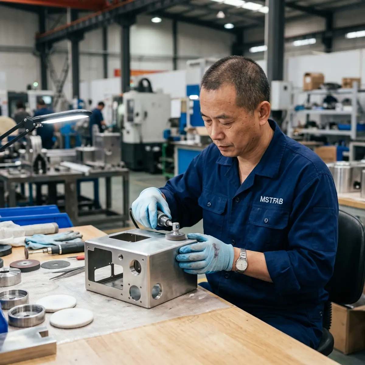
We offer specialized finishing options tailored specifically for test equipment environments:
- Architectural Fine-Texture Powder Coating: Applied in durable polyester or epoxy powders (RAL 7035 Light Grey, RAL 9005 Jet Black, or custom brand pantones). Fine-texture finishes hide fingerprint smudges, resist chemical cleaning wipes, and diffuse harsh overhead laboratory glare.
- Grained & Passivated Stainless Steel (SUS 304 / 316L): For sterile bio-analytical, pharmaceutical, and cleanroom test fixtures requiring daily alcohol or bleach sterilization. Finished in uniform #4 linear satin grain and passivated per ASTM A967.
- Anodized Aluminum (MIL-A-8625 Type II / III): Available in clear satin or matte black. Provides a tough, scratch-resistant surface finish with exceptional front-panel aesthetics.
- Precision Silk-Screening & Laser Etching: Clean, high-resolution port labeling, warning markings, and calibration branding baked onto the chassis with abrasion-resistant two-part epoxy inks.
7. Form Factors: Benchtop, 19-Inch Rackmount (1U–6U), and Modular Card Cages
Depending on your operational deployment, MSTFAB fabricates custom test equipment enclosures across three primary mechanical architectures:
- Benchtop Instruments: Compact two-piece clam-shell or wrap-around U-channel chassis equipped with fold-out tilt feet, front carry handles, and flush display windows.
- 19-Inch EIA-310 Rackmount Chassis: Heavy-gauge enclosures (1U, 2U, 3U, 4U up to 6U) built with heavy-duty structural side cheeks, integrated rack ears, and chassis slide rail mounting provisions designed to support heavy transformers and internal battery backups.
- Automated Test Fixture (ATE) Bed-of-Nails Enclosures: Heavy-duty welded and CNC-machined aluminum baseplates designed to withstand thousands of pneumatic clamping cycles without flexing probe pins.
8. 8-Point Engineering Checklist for Quoting Custom Test Equipment Enclosures
To help our DFM engineering team deliver a comprehensive feasibility review and binding quote within 24 hours, prepare the following project specifications:
- 1. 3D Solid Model: Exported in STEP (.stp AP214/AP242) format with internal PCB clearance envelopes.
- 2. 2D Production Drawing: Vector PDF identifying critical PCB mounting datums, general tolerances (ISO 2768-mK), and hardware specs.
- 3. Alloy & Temper: Aluminum 5052-H32 (standard for lightweight chassis), 6061-T6 (for machined front panels), or SPCC / SUS304.
- 4. Sheet Thickness: Nominal gauges (typically 1.2 mm, 1.5 mm, 2.0 mm, or 2.5 mm).
- 5. Hardware Insertion Part Numbers: Specific PEM fastener codes (e.g., PEM SO-M3-8ZI standoffs, FH-M4 studs).
- 6. Masking Blueprint: Clearly identified bare metal zones required for chassis grounding or EMI gasket contact.
- 7. Surface Finish & Color: RAL color code, gloss level, anodizing type, or brushed grain direction.
- 8. Batch Size: Prototype quantities (e.g., 5–25 pcs) and projected annual production volumes (e.g., 100–1,000 pcs).
Verified Manufacturing Standards for Test Instrument Enclosures:
- EIA-310-D: Cabinets, Racks, Panels, and Associated Equipment standard for 19-inch rackmount test chassis.
- ISO 2768-mK: General tolerances for linear dimensions and geometrical tolerances without individual callouts.
- MIL-DTL-5541: Chemical conversion coatings on aluminum and aluminum alloys for corrosion protection and electrical conductivity.
- ASTM B117: Standard practice for operating salt spray (fog) apparatus to validate corrosion resistance.
Frequently Asked Questions (FAQ)
Q1: What is the best sheet metal alloy for custom test equipment enclosures?
Aluminum 5052-H32 is the gold standard for custom test equipment enclosures. It provides superior strength-to-weight ratio, excellent thermal conductivity (138 W/m·K) for passive heat dissipation, natural non-magnetic properties, and superior corrosion resistance when paired with chromate conversion coating. If magnetic shielding against low-frequency transformers is required, cold-rolled steel (SPCC) or mu-metal internal sub-shields are recommended.
Q2: What tolerances can MSTFAB hold on high-density connector cutouts and PCB standoffs?
With CNC fiber laser cutting and automated optical alignment, we routinely hold ±0.05 mm (±0.002 in) on laser cutout diameters and center-to-center hole spacing across a flat plane. For overall formed profiles and bend heights on complex multi-flange enclosures, standard precision sheet metal tolerance is ±0.15 mm to ±0.2 mm per ISO 2768-m. Critical mating features can be finish-machined on multi-axis CNC mills if sub-0.05 mm tolerances are required.
Q3: How do you guarantee consistent electrical grounding across a powder-coated test enclosure?
Because powder coating forms an insulating dielectric barrier, we employ custom die-cut silicone masking dots and caps on all ground studs, PEM standoff mating faces, and perimeter flange contact pads before baking. Post-cure, masks are removed to expose raw, chromate-treated conductive aluminum. Every First Article is verified with a digital milli-ohmmeter to ensure chassis ground resistance remains strictly below 0.1 ohms.
Q4: What is the typical Minimum Order Quantity (MOQ) and lead time for test equipment enclosure prototypes?
Because our CNC fiber lasers and press brakes operate entirely from digital CAD files without expensive hard tooling, our MOQ is just 1 to 5 prototype units. Verification prototypes are typically manufactured, finished, and inspected within 5 to 7 business days, followed by fast air freight dispatch. Serial production batches (50 to 500+ units) are completed within 15 to 20 business days.
Request a 24-Hour DFM Review for Custom Test Equipment Enclosures
Partner with MSTFAB for your custom test equipment enclosures, benchtop instrument housings, and automated test fixture chassis. Submit your 3D CAD models (STEP) and 2D drawings to receive a comprehensive DFM review, thermal fitment assessment, and transparent factory quotation within 24 hours.
Sheet Metal Laser Cutting Services •
CNC Sheet Metal Bending •
Custom Enclosure RFQ Engineering
MSTFAB provides precision CNC laser cutting, press brake forming, hardware insertion, and powder coating for custom test equipment enclosures, electronic instrument shells, and industrial automation assemblies.
 WeChat Contact
 WhatsApp Me Directly