
⚡ Direct Answer: What Are Custom EV Charger Cable Holder Brackets?
Custom EV charger cable holder brackets are heavy-duty, weather-resistant structural sheet metal mounting assemblies, holsters, and articulated support arms engineered to cradle, route, counterbalance, and protect heavy charging cable assemblies on commercial Level 2 charging pedestals and ultra-fast DC fast chargers (DCFC, 150 kW to 480 kW+) as well as commercial Megawatt Charging Systems (MCS). Fabricated from 2.5 mm to 4.0 mm 304/316 stainless steel, heavy structural carbon steel (ASTM A36 / Q235B), or marine-grade 5052-H32 aluminum, these structural components perform six vital engineering functions: 1) Cantilever Torque & Dynamic Snatch Load Absorption (safely withstanding up to 350 N·m static bending moments and 1,200 N drive-off snag loads); 2) Cable Jacket & Internal Coolant Conduit Preservation (enforcing a minimum allowable bend radius Rbend ≥ 10 × Dcable across all operational axes to prevent internal hydraulic pinching and work-hardening of high-amp copper conductors); 3) Electromechanical Holster & Sensor Integration (providing CNC laser-cut apertures and threaded standoffs for magnetic proximity sensors, pilot microswitches, and anti-theft locking solenoids); 4) ADA Title III & Section 308 Accessibility Compliance (maintaining operable reach zones between 38 and 48 inches above finished grade with less than 5 lbf retrieval force); 5) IK10 Vandalism & Severe Public Impact Resistance; and 6) 15-Year Weatherability under ISO 12944 Category C5-M coastal salt-spray and highway deicing chemical environments.
Table of Contents: EV Cable Bracket Engineering Sourcing Guide
- 1. The Mechanical Physics of High-Power Liquid-Cooled EV Charging Cables
- 2. Cantilever Load Dynamics, Drive-Off Forces & Static Moment Calculations
- 3. Primary Mechanical Architectures: Fixed Saddles, Swivel Booms & Overhead Retractors
- 4. DFM Bend Radius Control & Cable Jacket Abrasion Elimination
- 5. Overhead Retractor Boom Kinematics & Counterweight Damping
- 6. Structural Finite Element Analysis (FEA) & Gusset Stiffening Principles
- 7. Failure Mode & Effects Analysis (FMEA): 6 Critical Bracket Failure Modes
- 8. Material Selection Matrix: 304/316 Stainless Steel vs. Structural Carbon Steel vs. 5052 Aluminum
- 9. Holster Proximity Sensors, Microswitches & Anti-Freeze Drainage DFM
- 10. ADA Accessibility Compliance (Section 308) & Ergonomic Pull-Force Standards
- 11. Precision Sheet Metal Fabrication Workflow: Laser Cutting, Radius Bending & Robotic Welding
- 12. Weld Joint Design & Fatigue Life Optimization: AWS D1.1, D1.2 & D1.6 Code Compliance
- 13. Surface Finishing & Corrosion Protection: C5-M Superdurable Powder Coating Systems
- 14. Vandalism, Shock & Impact Testing: IK10 Mechanical Verification
- 15. Hardware Clinching, Blind Rivet Nuts & Tamper-Proof Fasteners
- 16. Quality Metrology, CMM Inspection & AS9102 First Article Inspection (FAI)
- 17. OEM Sourcing Checklist & RFQ Specifications for EV Charging Metalwork
- 18. Comprehensive Engineering FAQs on EV Charger Cable Holder Brackets
1. The Mechanical Physics of High-Power Liquid-Cooled EV Charging Cables
As electric vehicle charging infrastructure expands beyond legacy 50 kW dispensers to 350 kW, 480 kW, and emerging 1.25 MW Megawatt Charging Systems (MCS) for commercial heavy-duty trucks and buses, the physical properties of charging cables undergo a dramatic escalation. In early Level 2 AC and 50 kW DC charging installations, charging cables were relatively light (3 kg to 6 kg), highly flexible, and could be loosely wrapped around a basic stamped plastic hook without risking structural damage.
However, in high-power DC fast charging (DCFC) delivering continuous currents between 350 A and 500 A (and up to 1,000 A under MCS architectures), air-cooled copper conductors become impractically thick and heavy. To satisfy temperature thresholds mandated by IEC 62196-3 and UL 2251 (limiting maximum handle surface temperature rise to ≤ 50 K above ambient), modern ultra-fast charging systems incorporate active internal liquid cooling loops. These coolant lines circulate a mixture of water-glycol or synthetic dielectric oils at pressures ranging from 3.0 bar to 6.5 bar alongside bundled high-amp multi-strand copper cores, auxiliary DC ground lines, CP/PP communication wires, and thick outer elastomer sheaths.
Physical Constraints of Liquid-Cooled Cable Assemblies
- Substantial Unit Mass: A standard 5-meter liquid-cooled CCS1, CCS2, or NACS (SAE J3400) cable assembly with an integrated cooling jacket and heavy connector handle weighs between 14 kg and 24 kg. This represents a heavy linear mass density of 2.8 kg to 4.8 kg per linear meter, creating immense static and dynamic loads on mounting points.
- High Torsional Rigidity: The combination of pressurized coolant tubes and internal braided shielding resists twisting. When an operator twists the cable to insert the connector into a vehicle inlet located on the opposite side of the parking stall, the cable acts as a stiff torsion spring, transferring severe torsional moments back to the dispenser mounting bracket.
- Extreme Cold-Weather Stiffening: In sub-zero winter climates (-30° C to -40° C), polyurethane (TPU) and synthetic rubber cable jackets undergo a dramatic increase in flexural modulus, stiffening by 300% to 500%. Bending a frozen cable requires significant physical force, multiplying the dynamic torque transferred into the bracket saddle and enclosure skin.
- Internal Hydraulic Collapse Vulnerability: If a heavy liquid-cooled cable is forced over a sharp sheet metal edge or hung on a hook with an insufficient radius, the internal flexible cooling tubes can kink or collapse. This restricts coolant circulation, causing the charging station’s thermal sensors to trigger an emergency thermal shutdown or permanently damaging expensive high-current liquid-cooled cable assemblies costing upwards of 3,500 each.
2. Cantilever Load Dynamics, Drive-Off Forces & Static Moment Calculations
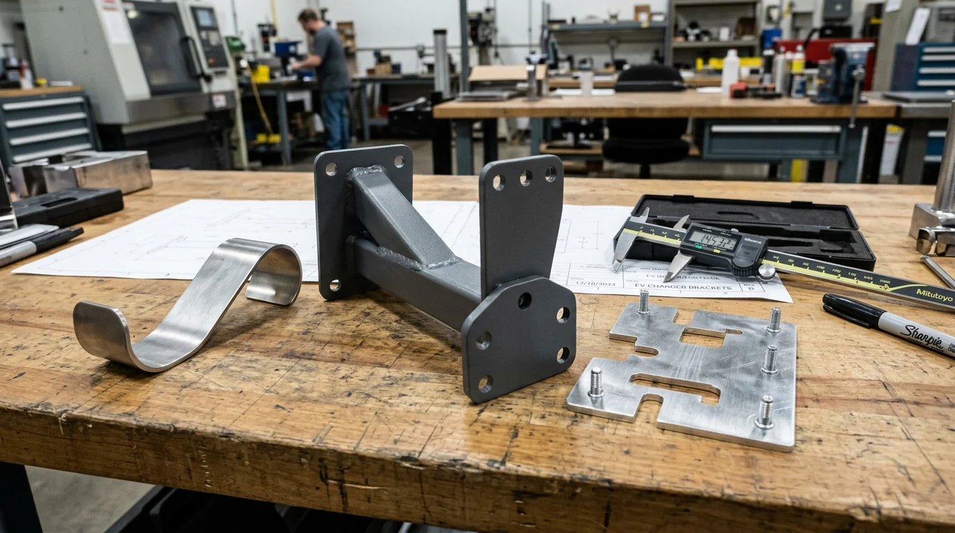
In public charging stations, the cable holder bracket acts as a classic cantilever beam extending perpendicularly from the charging pedestal or wall-mount enclosure. Understanding the mechanical statics and dynamic peak forces is essential for sizing sheet metal thickness, determining gusset geometry, and engineering internal chassis stiffeners.
Cantilever Static Moment Equation
The static bending moment (Mstaticin Newton-meters) exerted at the bracket root connection is expressed by:
Where:
- Fcable: The gravitational force of the coiled cable bundle resting on the saddle, calculated asmcable × g(N).
- Larm: The horizontal projection distance from the mounting face to the center of the cable saddle (m), typically 0.20 m to 0.45 m.
- Fnozzle: The gravitational force of the docked charging connector nozzle (N), typically 25 N to 45 N for heavy liquid-cooled handles.
- Lholster: The horizontal moment arm from the cabinet face to the center of mass of the holster receiver (m).
Dynamic Snatch & Accidental Drive-Off Loads
Static loads represent only a fraction of the mechanical stress encountered in real-world public charging plazas. Dynamic transient loads occur under three critical operational scenarios:
- Aggressive Retrieval & Dropping Shock: Drivers frequently pull cables sideways or drop heavy connectors from chest height. Dynamic deceleration forces amplify static loads by a dynamic shock factor (kdyn ≥ 2.5 to 3.5), creating instantaneous bending moments in excess of 150 N·m.
- Wind Buffeting on Coiled Loops: In exposed highway corridors and offshore coastal installations, sustained crosswinds of 120 km/h (33 m/s) generate substantial aerodynamic drag and vortex-induced vibrations across suspended cable loops, inducing continuous low-cycle fatigue at the bracket root.
- Accidental Drive-Off Snag Loads: If a vehicle begins moving before the cable is safely disconnected, or if an adjacent vehicle snag the cable loop, horizontal snatch forces can instantaneously exceed 1,500 N. The bracket must be engineered with controlled plastic deformation characteristics or shear-pin breakaway features to prevent structural destruction of the main electrical cabinet.
| EV Charger Class | Cable Format & Mass | Cantilever Overhang (Larm) | Peak Dynamic Moment | Recommended Minimum Thickness |
|---|---|---|---|---|
| Level 2 Commercial AC (7.2kW – 22kW) | Air-cooled Type 1 / Type 2 (4 kg – 7 kg) | 120 mm – 180 mm | 35 N·m – 60 N·m | 2.0 mm (14 ga) 304 SS / Aluzinc |
| Standard DC Fast Charger (50kW – 150kW) | Heavy air-cooled CCS / CHAdeMO (10 kg – 15 kg) | 200 mm – 280 mm | 80 N·m – 140 N·m | 2.5 mm – 3.0 mm (12 to 11 ga) Steel |
| Ultra-Fast Liquid-Cooled DCFC (250kW – 480kW) | Liquid-cooled CCS1 / NACS (16 kg – 24 kg) | 300 mm – 400 mm | 180 N·m – 280 N·m | 3.0 mm – 4.0 mm Structural Steel + Gussets |
| Megawatt Commercial Fleet Dispenser (MCS) | Heavy Megawatt liquid bundle (25 kg – 38 kg) | 450 mm – 650 mm (Articulated Boom) | 450 N·m – 680 N·m | 4.0 mm – 6.0 mm Welded Truss Architecture |
3. Primary Mechanical Architectures: Fixed Saddles, Swivel Booms & Overhead Retractors
EV charging hardware designers select bracket geometries based on installation layout, parking geometry, accessibility regulations, and cable mass. MSTFAB engineers and fabricates three fundamental bracket architectures:
1. Pedestal-Mounted Curved Saddle Brackets
The most widely deployed configuration across public urban charging networks is the cabinet-mounted fixed saddle. Formed from a single laser-cut blank or welded from heavy plate, the saddle provides an ergonomic resting trough for coiling 3 to 4 loops of charging cable. A separate or integrated lower holster holds the connector plug securely in an angled, downward-facing position to prevent water ingress.
Chassis Tie-In Integration: Because the dispenser’s external cosmetic panel is typically fabricated from 1.5 mm to 2.0 mm aluminum or sheet steel, mounting a heavy cantilever bracket directly to the outer skin leads to immediate oil-canning and weld failure. MSTFAB provides heavy internal chassis backing plates (doubler plates) that clamp across the enclosure skin, routing cantilever loads directly into the main vertical corner posts and concrete anchor studs.
2. 180° Articulated Swivel Support Arms
In dual-port dispensers positioned between two parking spaces, or in multi-level parking structures where space is constrained, fixed brackets force the cable to drag across concrete curbs. Articulated swivel brackets feature a heavy horizontal arm attached to the charger via a precision CNC-machined pivot bearing assembly:
- Precision Machined Pivot Hub: Consists of a 304 stainless steel or carbon steel pivot pin rotating within self-lubricating bronze (SAE 660) or acetal sleeve bushings that require zero maintenance over a 15-year service life.
- Mechanical Detent Stops: Spring-loaded detents lock the arm at 0° (stowed flush against cabinet), 90° (service position), and 180° (extended towards vehicle), preventing the boom from swinging wildly in gusty winds.
- Internal Rotational Cable Clamping: A pivoting saddle head ensures that cable twist is converted into smooth swivel rotation rather than concentrated torsional shear on the cable sheath.
3. Spring-Assisted Overhead Cable Retractor Booms
Overhead retractor towers are mandatory for fleet depots and premium public charging plazas deploying heavy 350 kW+ liquid-cooled cables. An elevated boom arm extends overhead (2.4 m to 2.8 m above ground), suspending the cable bundle via an aircraft-grade stainless steel tension wire connected to an internal constant-force spring balancer. The cable hangs gracefully above the ground, eliminating tripping hazards, vehicular run-over incidents, and puddles of snow, oil, and gravel.
4. DFM Bend Radius Control & Cable Jacket Abrasion Elimination
Replacing a damaged liquid-cooled charging cable costs an operator between 2,500 and 4,500, including specialized fluid bleeding, pressure testing, and field technician labor. Improperly designed sheet metal cable brackets are the number one cause of premature jacket perforation and hydraulic line pinching.
DFM Design Rules for Cable-Contact Geometries
- The10 × DCurvature Mandate: The resting saddle curvature radius (Rsaddle) must equal or exceed 10 × the outside cable diameter (Dcable). For a standard 36 mm OD liquid-cooled cable, the minimum saddle curvature must beige 360 mmacross the entire arc of support. Never utilize sharp V-notches or angular knife-edge bends.
- Multi-Axis CNC Radius Deburring (R ≥ 1.2 mm): Fiber laser cutting produces sharp right-angle edges and microscopic pierce spatter. MSTFAB runs all cable-contact sheet metal parts through an automated rotary-brush deburring and edge-rounding system. All sheet edges contacting the cable are radiused to a minimum of 1.2 mm, ensuring zero burrs or cutting edges can score the outer rubber jacket.
- Flanged Edge Hemming / Curl Forming: For ultra-high reliability, the sheet metal edges of the cable cradle are formed with a 180° teardrop hem or a 90° outward curl. This presents a completely smooth, continuous cylindrical metal contour to the cable jacket, eliminating edge contact entirely.
- Snap-In Vulcanized EPDM Protective Liners: For harsh outdoor environments, MSTFAB designs snap-in molded EPDM or UV-stabilized Santoprene TPE rubber cushions. These cushions lock into laser-cut retaining tabs on the sheet metal saddle without messy glues or fasteners, absorbing dynamic vibrations and providing a soft, non-abrasive resting surface.
5. Overhead Retractor Boom Kinematics & Counterweight Damping
When engineering overhead cable management systems (CMS) for 350 kW to Megawatt dispensers, sheet metal brackets interface with dynamic mechanical mechanisms. The goal of an overhead retractor is to balance the vertical mass of the cable so that the driver feels an effective weight of less than 2.0 kg (4.4 lbs) during vehicle plug-in.
Kinematics & Spring Balancer Engineering
- Constant-Force Spiral Spring Enclosures: The sheet metal retractor housing must accommodate a sealed spring drum mechanism. MSTFAB laser-cuts heavy mounting bulkheads (3.0 mm galvanized or stainless steel) that locate the spring drum precisely aligned with the payout sheave, preventing wire rope fraying.
- UHMWPE Cable Pulley Sheaves: The high-tensile 316 stainless steel aircraft wire rope (3.2 mm diameter, 7×19 construction) routes over CNC-machined Ultra-High-Molecular-Weight Polyethylene (UHMWPE) guide pulleys. UHMWPE provides a friction coefficient of μ ≤ 0.12and eliminates metallic contact noise and wire galling.
- Hydraulic End-of-Stroke Dampers: When a driver unplugs from the car and releases the handle, the spring retractor pulls the cable rapidly upwards. To prevent violent impact when the cable reaches its stowed limit, MSTFAB integrates mounting tabs for miniature sealed hydraulic shock absorbers or elastomeric progressive bump stops, dampening peak deceleration loads.
- Dual-Pivot Overhead Articulation: The overhead boom features a horizontal swivel joint at the tower mast and a vertical articulation joint at the cable clamp. Both joints incorporate heavy gusseted hinge brackets capable of resisting 2,000 N wind gust moments without binding or creaking.
6. Structural Finite Element Analysis (FEA) & Gusset Stiffening Principles
Cantilever brackets subjected to cyclic dynamic loads are highly prone to structural fatigue failure at the root bend radius. Over hundreds of thousands of charging cycles, small micro-cracks form in the heat-affected zone (HAZ) or high-strain bend regions, eventually leading to catastrophic structural rupture. MSTFAB deploys advanced Finite Element Analysis (FEA) to validate stress distribution and optimize stiffening gussets prior to hard tooling:
FEA Optimization Principles for High-Stress Brackets
- Continuous Brake-Formed Return Flanges: Adding a 15 mm to 20 mm 90° return flange along the perimeter edges of the bracket arm increases the cross-sectional area moment of inertia (Ixx) by up to 450% compared to an unformed flat laser-cut plate. This eliminates visible elastic sagging when a heavy 20 kg cable bundle is docked.
- Full-Penetration Welded Triangular Gussets: Where the cantilever boom meets the vertical mounting baseplate, maximum bending stress concentrates at the inner corner. MSTFAB incorporates symmetric triangular stiffening gussets. Welding parameters follow AWS D1.1 (structural carbon steel) and AWS D1.6 (stainless steel), ensuring 100% throat penetration with smooth, concave weld toes that minimize notch stress concentrations.
- Stress Concentration Attenuation at Fastener Holes: Bolting a bracket to a cabinet creates localized stress concentrations around fastener clearance holes. MSTFAB incorporates cold-formed embossed stiffening rims around mounting holes or utilizes welded collar bushings that spread clamping preloads over a broad area, preventing sheet metal cracking under cyclic fatigue.

7. Failure Mode & Effects Analysis (FMEA): 6 Critical Bracket Failure Modes
Through years of contract manufacturing for Tier-1 EVSE equipment manufacturers, MSTFAB has compiled an exhaustive Failure Mode and Effects Analysis (FMEA) for outdoor charging cable mounting assemblies:
| Failure Mode | Root Cause Mechanism | Severity | MSTFAB Sheet Metal DFM Countermeasure |
|---|---|---|---|
| 1. Cabinet Skin Oil-Canning & Tearing | Direct mounting to 1.5mm thin outer skin without internal load distribution. | High (Structural) | Internal 3.0mm structural backing plate tying directly to vertical frame uprights. |
| 2. Root Bend Fatigue Fracture | Sharp internal bend radius causing micro-fissures and cyclic bending fatigue. | Critical (Rupture) | Generous punch radius (R ≥ 2× t) plus full-length welded triangular gusset plates. |
| 3. Cable Sheath Slicing & Fluid Leak | Burrs on laser-cut sheet edges slicing jacket during high-angle pulls. | Critical (3,500 Part) | Automated rotary brush deburring (R ≥ 1.2mm) and snap-in EPDM liners. |
| 4. Frozen Holster Lockup | Water pooling in closed holster cavity freezing connector latch solid in winter. | Moderate (Station Down) | CNC laser-cut 8mm angled drainage slots at lowest gravity collection basin. |
| 5. Creep Corrosion & Paint Flaking | Edge thinning of powder coat along sharp 90° laser edges exposed to road salts. | Moderate (Aesthetic) | Mechanical edge-rounding + Zinc-rich primer + Superdurable polyester topcoat (C5-M). |
| 6. Swivel Arm Seizure / Galling | Metal-on-metal friction between stainless pin and bushing galling over time. | Moderate (Maintenance) | Self-lubricating oil-impregnated sintered bronze or engineered acetal sleeve bearings. |
8. Material Selection Matrix: 304/316 Stainless Steel vs. Structural Carbon Steel vs. 5052 Aluminum
Selecting the optimal metal alloy involves balancing structural stiffness, total mass, corrosion resistance, and manufacturing economics:
| Material Grade | Yield Strength | Modulus of Elasticity (E) | Salt Spray Resistance (ASTM B117) | Best Practical Application |
|---|---|---|---|---|
| Austenitic Stainless Steel 304 (1.4301) | 215 – 240 MPa | 193 GPa | 1,000+ Hours (Passivated) | Premium Industry Standard: Public DC fast chargers, retail parking plazas, temperate urban hubs. |
| Marine-Grade Stainless 316L (1.4404) | 220 – 260 MPa | 193 GPa | 2,500+ Hours (C5-M Marine) | Coastal highway corridors, ferry terminals, island microgrid charging depots. |
| Structural Carbon Steel (ASTM A36 / Q235B) | 250 – 355 MPa | 205 GPa (Maximum Stiffness) | 1,500 Hours (Zinc Primer + Topcoat) | High-Load Megawatt Arms: Commercial fleet depots, heavy transit bus retractor masts. |
| Aluminum 5052-H32 | 190 – 215 MPa | 70 GPa (Lightwe) | 1,000 Hours (Chromate + Powder Coat) | Lightweight Level 2 wall-mount stations, mobile rapid charging carts. |
9. Holster Proximity Sensors, Microswitches & Anti-Freeze Drainage DFM
A modern EV charger cable bracket does not merely hold dead weight; it interfaces directly with the charging station controller (CCU). The holster housing must accommodate electromechanical sensors that detect whether the charging plug is securely docked:
Electronic Integration & Drainage DFM
- Magnetic Proximity & Reed Switch Cutouts: Laser-cut mounting slots allow adjustable positioning of IP67 magnetic sensors that register handle insertion without physical mechanical contact wear.
- Anti-Freeze Gravity Weep Drainage: In outdoor winter conditions, melted snow and wind-driven rain pool inside the holster receptacle. If the water freezes overnight, the ice locks the charging plug into the holster, rendering the station inoperable. MSTFAB cuts dedicated 8 mm downward-angled drainage channels at the lowest point of the holster cavity.
- Locking Solenoid Gate Integration: To prevent public theft or vandalism of expensive DC cables during non-operating hours, brackets can be detailed with internal solenoid mounting tabs that lock the latch hook until credit card authorization is received.
- Internal Cable Routing Channels: Low-voltage wiring harness runs from the holster microswitch into the main cabinet through dedicated, grommeted sheet metal conduits, protecting electrical signal wires from external tampering or accidental pinching.
10. ADA Accessibility Compliance (Section 308) & Ergonomic Pull-Force Standards
In North America, public EV charging stations funded by federal programs (such as NEVI – National Electric Vehicle Infrastructure) must strictly comply with the Americans with Disabilities Act (ADA) Title III regulations and Section 308 Operable Parts guidelines. In Europe, equivalent accessibility mandates are defined under EN 301 549:
Key Accessibility & Ergonomic DFM Parameters
- Maximum Reach Height (Section 308.2 & 308.3): The charging connector handle and holster bracket must be positioned between 24 inches (610 mm) and 48 inches (1,220 mm) above the finished parking pad grade. MSTFAB standardizes holster bracket mounting centerlines at 38 to 42 inches (965 mm to 1,065 mm), comfortably within the unobstructed forward and side reach zones for wheelchair users.
- Operable Force Limits (≤ 5.0 lbf / 22.2 N): Unholstering the connector handle and retrieving the cable must require no more than 5 pounds-force (22.2 N). This rule makes heavy counterbalanced retractor arms essential for liquid-cooled cables weighing over 15 kg. MSTFAB’s overhead counterweight and spring balancer systems reduce the operator’s perceived pull force to less than 3.5 lbf (15.5 N).
- One-Handed Operation Without Wrist Twisting: Holster latch brackets are designed with flared self-guiding receiver mouths. This allows drivers with limited hand dexterity or arthritis to re-dock the heavy plug smoothly using a straight forward push without requiring tight grasping, pinching, or twisting of the wrist.
- Ground Clearance & Trip Hazard Elimination: Cables resting on lower saddle hooks must maintain a minimum ground clearance of 18 inches (450 mm) to prevent cable coils from laying on snow, ice, or pooling water, while ensuring that the lowest loop does not obstruct wheelchair footrests.
11. Precision Sheet Metal Fabrication Workflow: Laser Cutting, Radius Bending & Robotic Welding
At MSTFAB, high-volume production of EV charging brackets is executed on automated CNC production lines governed by ISO 9001:2015 quality standards:
- 15kW Fiber Laser Cutting with Automated Pallet Exchanger: Profiles blanks from prime certified sheet metal using 99.999% pure nitrogen assist gas. Edge cutouts hold ±0.05 mm tolerances with zero dross.
- Multi-Head Rotary Edge Deburring & Rounding: Oscillating abrasive brushes break sharp edges, ensuring that all surfaces contacting the cable jacket conform to strict radius standards (R ≥ 1.2 mm).
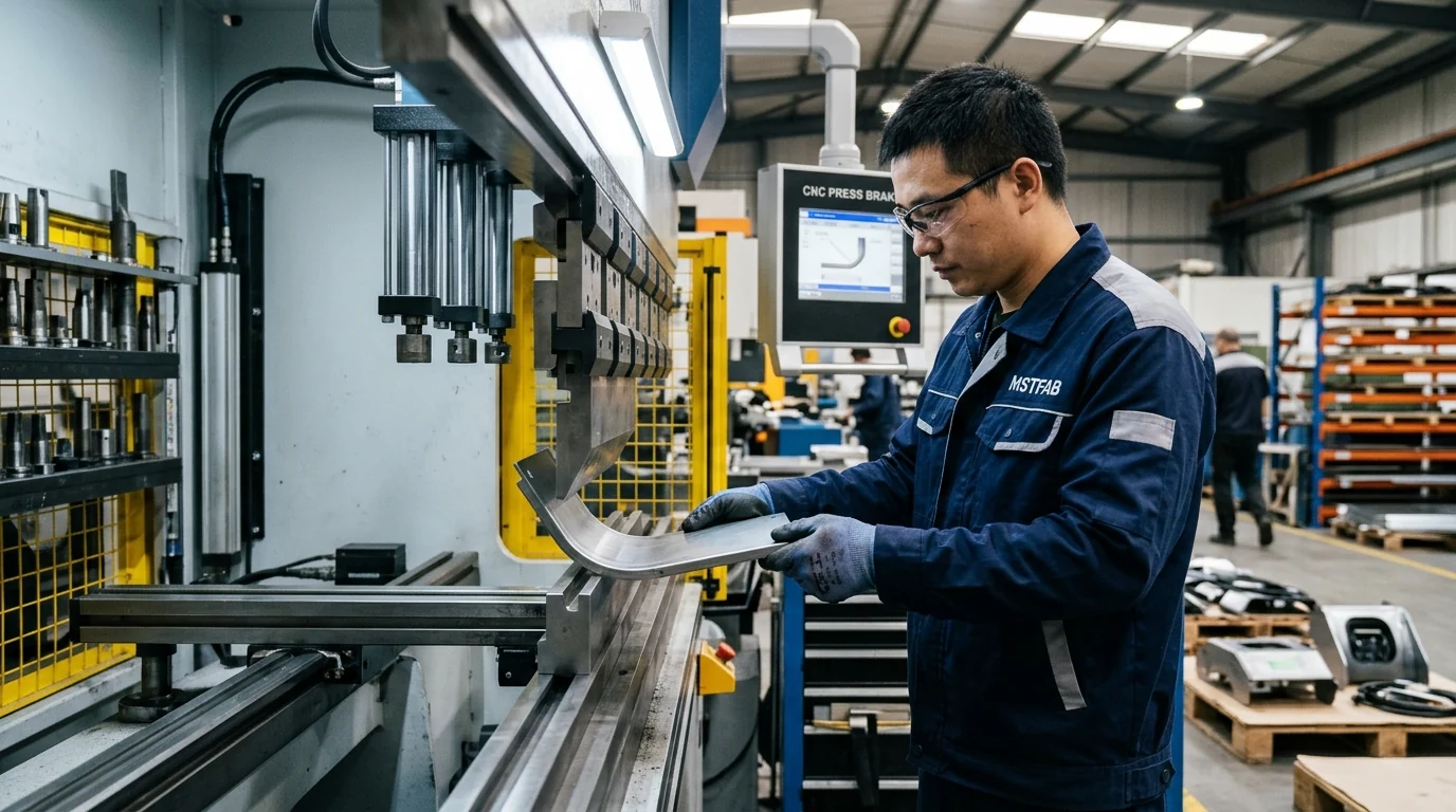
- 7-Axis Multi-Bend CNC Press Brake Forming: Bends are executed using custom-ground radius punches that match the specified cable cradle curvature without creating fracture lines or tool marks.
- Robotic TIG & Cold Metal Transfer (CMT) Welding: Gusset seams are welded on dedicated modular 3D fixturing tables that eliminate thermal distortion, holding perpendicularity within 0.5°.
- Automated Hardware Clinching: Heavy-duty self-clinching studs and nuts are installed with monitored hydraulic dwell time to ensure maximum push-out retention.
12. Weld Joint Design & Fatigue Life Optimization: AWS D1.1, D1.2 & D1.6 Code Compliance
Welded joints on cantilever cable brackets undergo cyclic tension-compression stresses during daily operation. Poor weld design or improper heat input results in severe localized embrittlement and catastrophic joint failure. MSTFAB applies strict structural welding codes:
Welding Best Practices for High-Stress Sheet Metal Brackets
- AWS Code Certification: Welds on carbon steel comply with AWS D1.1; aluminum welds comply with AWS D1.2; stainless steel fabrications comply with AWS D1.6. All welding operators and robotic programs are certified to AWS structural welding qualifications.
- Effective Throat Thickness Optimization: For fillet welds joining 3.0 mm gusset plates to 4.0 mm baseplates, the effective throat thickness (a) is strictly maintained at a ≥ 0.707 × tthin ≥ 2.1 mm. This ensures that the weld joint exhibits higher tensile capacity than the parent metal.
- Cold Metal Transfer (CMT) for Ultra-Low Heat Input: On 5052 aluminum and 304 stainless steel assemblies, MSTFAB utilizes Fronius CMT robotic welding technology. The droplet detachment is controlled mechanically, reducing heat input by up to 60% compared to conventional pulsed MIG. This prevents burn-through, eliminates spatter, and minimizes heat-affected zone (HAZ) grain coarsening.
- 100% Visual & Liquid Penetrant Inspection (DPI): Every production batch undergoes visual weld inspection under 10x magnification. Highly critical structural retractor boom joints undergo ASTM E165 liquid penetrant testing to verify zero surface porosity, incomplete fusion, or micro-fissuring.
13. Surface Finishing & Corrosion Protection: C5-M Superdurable Powder Coating Systems
Installed along coastal highways and urban streets exposed to road salt (calcium chloride and sodium chloride), EV charging hardware faces severe atmospheric corrosivity classified under ISO 12944 as Category C4 to C5-M. A rusted cable bracket destroys consumer trust and damages the operator’s brand equity.
MSTFAB Multi-Tiered Finishing Protocol
- 5-Stage Automated Chemical Pretreatment: Degreasing, acid etching, and non-chrome zirconium or iron phosphate conversion coating establish optimal microscopic mechanical adhesion.
- Epoxy Zinc-Rich Primer Application (50–70 µm): Provides sacrificial cathodic protection that prevents rust creep if the coating is scratched by dropped connectors.
- Qualicoat Class 2 / AAMA 2604 Superdurable Polyester Topcoat (60–80 µm): Delivers outstanding UV gloss retention and chemical resistance against car wash detergents, battery acid, and graffiti solvents. Total dry film thickness (DFT) reaches 110 µm to 150 µm.
14. Vandalism, Shock & Impact Testing: IK10 Mechanical Verification
Under international standard IEC 62262 and UL 2202, outdoor charging equipment installed in public spaces must meet IK10 mechanical impact protection:
- 20-Joule Steel Mass Impact Test: A 5.0 kg steel pendulum hammer dropped from a height of 400 mm impacts the cable cradle and support arm. The bracket must absorb the kinetic energy without structural fracturing or seam weld rupture.
- Cantilever Snatch & Overload Test: A 1,200 N downward static test load is applied at the outer tip of the support arm for 60 seconds. Permanent plastic deformation must remain below 1.5 mm, ensuring continued alignment with mating cabinet fasteners.
15. Hardware Clinching, Blind Rivet Nuts & Tamper-Proof Fasteners
To prevent theft and simplify field assembly, MSTFAB integrates specialized fastening systems into every bracket:
- Self-Clinching Heavy Studs (PennEngineering PEM FHS Series): Installed prior to powder coating, providing threaded studs that eliminate loose bolt handling inside crowded dispenser cabinets.
- High-Torque Blind Rivet Nuts (Heavy Hex Body): Used when mating to closed hollow structural tube frames, providing M8 to M12 internal threads with high spin-out resistance.
- Pin-in-Torx & Snake-Eye Security Fasteners: Visible exterior mounting bolts feature tamper-resistant drive geometries, preventing unauthorized removal with standard hand wrenches.
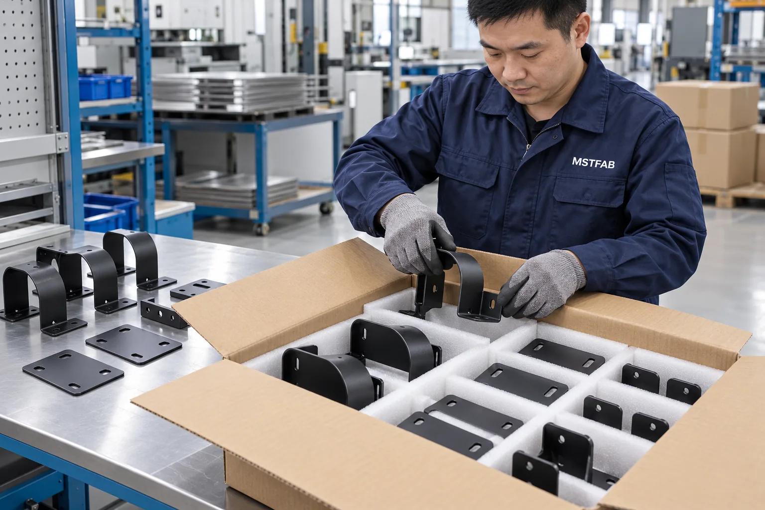
16. Quality Metrology, CMM Inspection & AS9102 First Article Inspection (FAI)
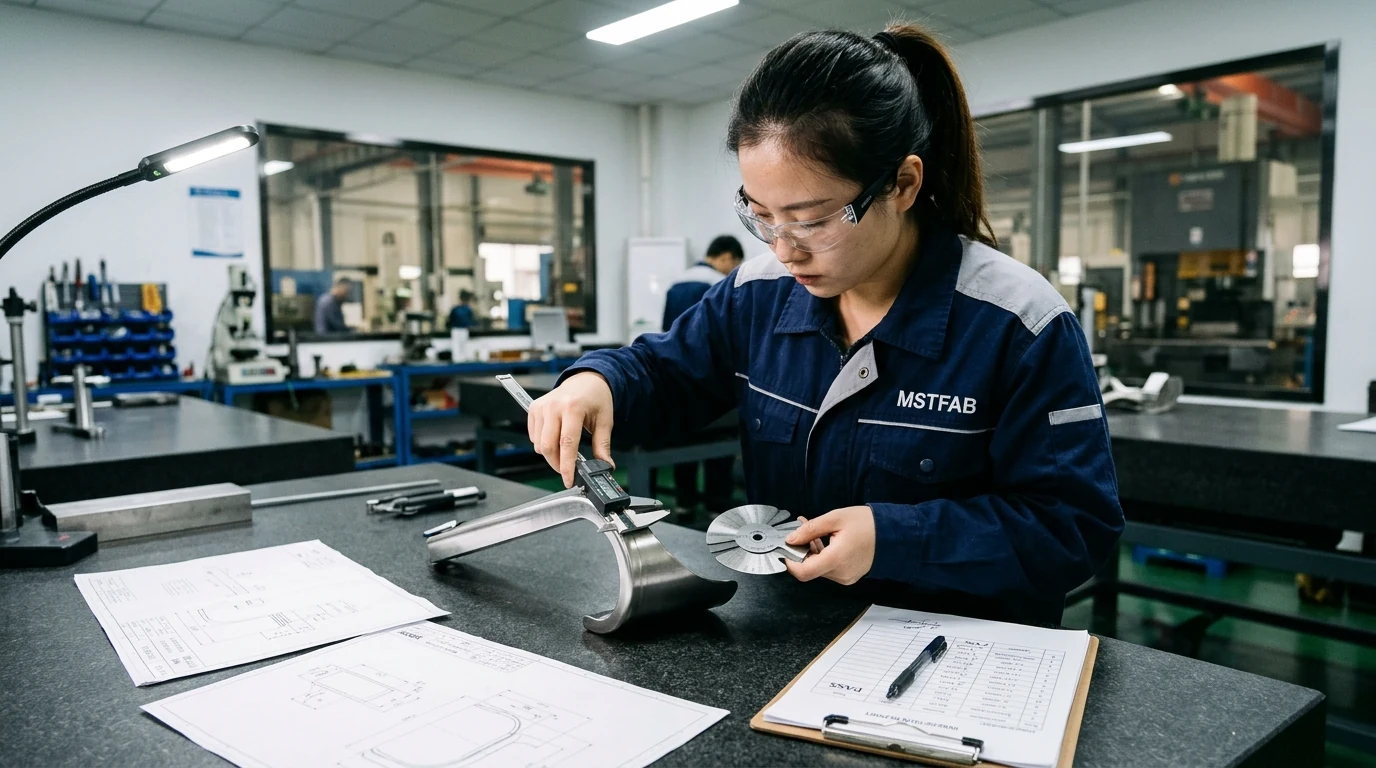
Every production run of custom EV charging brackets is backed by comprehensive First Article Inspection (FAI) documentation in our climate-controlled metrology laboratory:
- Zeiss Bridge CMM Verification: 100% measurement of mounting hole positions, pin-to-hole centerlines, and bracket squareness to ±0.05 mm.
- Coating Dry Film Thickness (DFT) & Adhesion Testing: Digital electromagnetic gauge logging and ASTM D3359 cross-hatch tape adhesion tests (Grade 5B pass).
- Mill Test Reports (MTR): Certified material certificates documenting chemical composition and yield strength for every coil batch.
17. OEM Sourcing Checklist & RFQ Specifications for EV Charging Metalwork
To receive an actionable, binding manufacturing quotation and comprehensive DFM review within 24 hours, provide the following engineering files to MSTFAB:
- Complete 3D CAD Assembly (.STEP / .STP): Native solid models showing the bracket, cable resting trajectory, mounting interface, and internal gusseting.
- 2D Engineering Drawings (.PDF): Fully dimensioned prints defining general tolerances (ISO 2768-mK), designated Critical-to-Quality (CTQ) hole centers, and weld callouts.
- Target Cable Diameter & Weight Specifications: Outside diameter (Dcable), total hanging mass, and minimum permissible bend radius.
- Environmental Rating Requirements: Target corrosivity category (e.g., C4 Industrial or C5-M Marine), salt spray test hours (ASTM B117), and powder coat RAL color code.
- Scheduled Release Volumes: Prototype quantity (e.g., 20 pcs FAI) and estimated annual production volume (EAU) to lock in volume tiered pricing.
Verified Engineering Standards & Regulatory References:
- UL 2202 Electric Vehicle (EV) Charging System Equipment – Safety and structural support standards for commercial EV chargers.
- IEC 62196 Plugs, Socket-Outlets, and Vehicle Connectors – Dimensional and mechanical strain relief criteria for charging couplers.
- IEC 62262 Degrees of Protection Against External Mechanical Impacts (IK Code) – IK10 high-impact resistance for public charging infrastructure.
- ASTM B117 Salt Spray Corrosion Testing – Outdoor weathering and salt fog performance for EV charger brackets.
Partner with a Tier-1 EV Charging Metalwork Manufacturer
MSTFAB manufactures custom cable holder brackets, heavy support arms, filter frames, and complete weather-resistant enclosures for the world’s leading EV charging equipment manufacturers. Upload your drawings today for a rapid 24-hour DFM engineering review and firm quotation.
18. Comprehensive Engineering FAQs on EV Charger Cable Holder Brackets
1. What is the minimum bend radius required for liquid-cooled DC fast charging cables?
Under major connector manufacturer specifications (such as Phoenix Contact, Huber+Suhner, and ITT Cannon), liquid-cooled DC cables require a minimum dynamic bend radius of at least 10 times the outside cable diameter (R ≥ 10 × D). For a typical 36 mm cable, the bracket saddle must provide at least a 360 mm radius curve to prevent internal coolant flow restriction and copper conductor fatigue.
2. How do you prevent the bracket from bending or tearing the charger cabinet sheet metal skin?
We manufacture internal structural backing plates (doubler plates) fabricated from 3.0 mm galvanized or stainless steel that bolt inside the enclosure skin. This structural sandwich transfers the cantilever bending moment directly into the dispenser’s internal vertical corner uprights, completely isolating the cosmetic outer sheet metal panel from tearing or oil-canning.
3. Can MSTFAB integrate proximity microswitches and holster lock mechanisms?
Yes. We laser-cut precision mounting holes and threaded standoffs for magnetic reed sensors, microswitches, and electronic locking solenoids per your electrical BOM. We also provide internal wiring conduits and tie-off saddles to route low-voltage sensor cabling safely into the main electrical chassis.
4. How does MSTFAB achieve IK10 impact resistance on sheet metal EV cable brackets?
We utilize heavy-gauge (3.0 mm to 4.0 mm) high-tensile structural steel (Q235B / A36) or 304 stainless steel reinforced with continuous 45° brake-formed stiffening flanges and fully penetrated robotically welded triangular gussets. This monolithic geometry dissipates 20-Joule dynamic impacts without permanent deformation or joint cracking.
5. What powder coating specifications are recommended for outdoor EV charger cable brackets?
We recommend a dual-coat system complying with Qualicoat Class 2 or AAMA 2604: an epoxy zinc-rich primer (50–70 µm) followed by a superdurable TGIC-free polyester topcoat (60–80 µm). This coating withstands over 1,500 hours of ASTM B117 salt spray testing and maintains color and gloss under intense solar UV exposure.
6. What is MSTFAB’s prototype and production turnaround time for custom EV brackets?
Rapid prototyping and First Article Inspection (FAI) pilot samples are typically completed within 5 to 7 working days. Production orders (500 to 5,000+ units) typically ship within 2 to 3 weeks, supported by blanket purchase order inventory programs and scheduled releases.
7. How do your brackets ensure compliance with ADA Section 308 accessibility rules?
We standardize holster mounting heights between 38 and 42 inches above grade, ensuring full forward and parallel reach compliance for wheelchair users under ADA Section 308. Furthermore, we engineer counterbalanced overhead retractor systems that limit the operational unholstering force to less than 5 lbf (22.2 N).
8. How do you prevent winter freeze-up inside the charging plug holster?
We laser-cut downward-sloped 8 mm drainage weep channels at the lowest point of the holster receiver cup. Even during heavy sleet and freezing rain, pooled water discharges by gravity before it can freeze around the connector latch hook.
 WeChat Contact
 WhatsApp Me Directly